wheel nut MITSUBISHI L200 2010 4.G Owners Manual
[x] Cancel search | Manufacturer: MITSUBISHI, Model Year: 2010, Model line: L200, Model: MITSUBISHI L200 2010 4.GPages: 369, PDF Size: 30.72 MB
Page 125 of 369
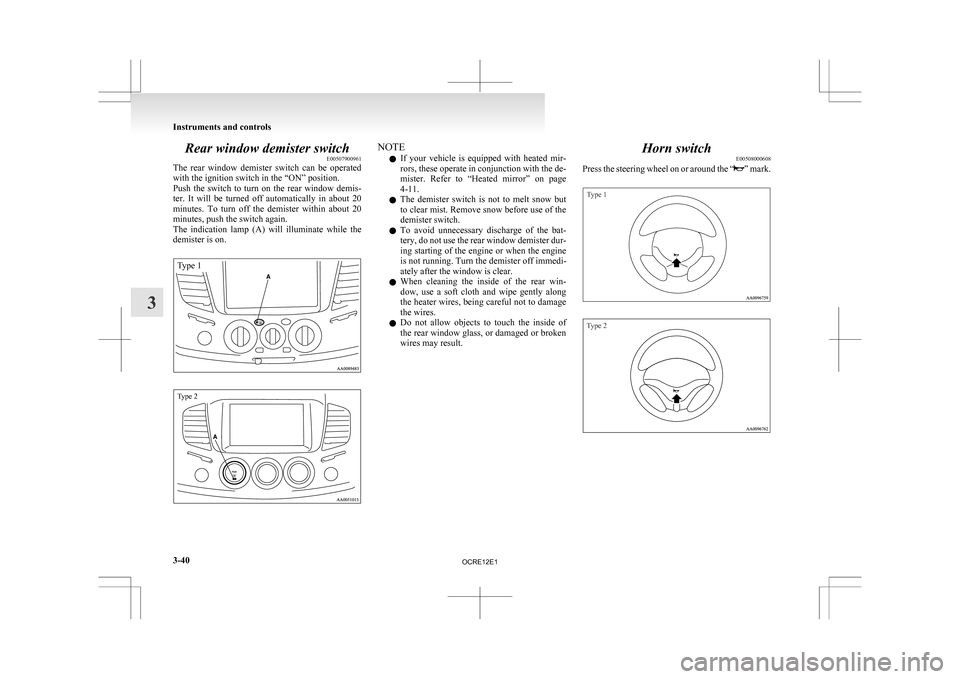
Rear window demister switch
E00507900961
The
rear window demister switch can be operated
with the ignition switch in the “ON” position.
Push the switch to turn on the rear window demis-
ter. It will be turned off automatically in about 20
minutes. To turn off the demister within about 20
minutes, push the switch again.
The indication lamp (A) will illuminate while the
demister is on.
Type 1
Type 2 NOTE
l If
your vehicle is equipped with heated mir-
rors, these operate in conjunction with the de-
mister. Refer to “Heated mirror” on page
4-11.
l The demister switch is not to melt snow but
to clear mist. Remove snow before use of the
demister switch.
l To avoid unnecessary discharge of the bat-
tery, do not use the rear window demister dur-
ing starting of the engine or when the engine
is not running. Turn the demister off immedi-
ately after the window is clear.
l When cleaning the inside of the rear win-
dow, use a soft cloth and wipe gently along
the heater wires, being careful not to damage
the wires.
l Do not allow objects to touch the inside of
the rear window glass, or damaged or broken
wires may result. Horn switch
E00508000608
Press
the steering wheel on or around the “ ”
mark.
Type 1
Type 2Instruments and controls
3-40
3
OCRE12E1
Page 136 of 369
Push the switch to fold the mirrors inward, and
push
the switch again to return them to extended po-
sition. NOTE
l It
is also possible to fold and return the mir-
rors by hand.
l When freezing has occurred and mirrors fail
to operate as intended, please refrain from re-
peated pushing of the retractor switch as this
action can result in burn-out of the mirror mo-
tor circuits.
Heated mirror* E00601200253
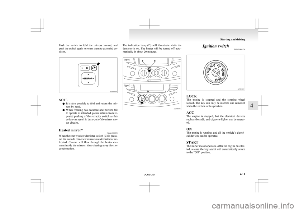
When the rear window demister switch (C) is press-
ed,
the outside rear-view mirrors are demisted or de-
frosted. Current will flow through the heater ele-
ment inside the mirrors, thus clearing away frost or
condensation. The indication lamp (D) will illuminate while the
demister
is on. The heater will be turned off auto-
matically in about 20 minutes.
Type 1
Type 2 Ignition switch
E00601401874 LOCK
The
engine is stopped and the steering wheel
locked. The key can only be inserted and removed
when the switch in this position.
ACC
The engine is stopped, but the electrical devices
such as the radio and cigarette lighter can be operat-
ed.
ON
The engine is running, and all the vehicle’s electri-
cal devices can be operated.
START
The starter motor operates. After the engine has star-
ted, release the key and it will automatically return
to the “ON” position. Starting and driving
4-11 4
OCRE12E1
Page 171 of 369
If the warning lamp illuminates while
driving
E00607300663
If only the ABS warning lamp illuminates l Avoid
hard braking and high-speed driving.
Stop the vehicle in a safe place.
Restart the engine and check to see whether
the lamp goes out after a few minutes driv-
ing; if it then remains off during driving,
there is no problem.
However, if the lamp does not go out, or if it
lights up again when the vehicle is driven,
we recommend you to have the vehicle
checked as soon as possible.
l The ABS warning lamp can illuminate if the
battery voltage is insufficient when the en-
gine is started. In this case, it does not indi-
cate an ABS fault.
Charge the battery by allowing the engine to
idle for a while.
If the battery has been charged but the ABS
warning lamp continues to illuminate or illu-
minates intermittently, have the vehicle in-
spected.
If the ABS warning lamp and brake warning
lamp illuminate at the same time l The ABS and brake force distribution func-
tion may not work, so hard braking could
make the vehicle unstable.
Avoid hard braking and high-speed driving.
Stop the vehicle in a safe place and contact a
MITSUBISHI MOTORS Authorized Service
Point. NOTE
l Immediately
after the vehicle starts moving
after engine start up, a whining sound of a mo-
tor will be heard from the engine compart-
ment. If the brake pedal is depressed at that
moment, you can feel the brake pedal pulsat-
ing.
This pulsation is due to the self-diagnosis op-
eration of the ABS and does not indicate a
malfunction.
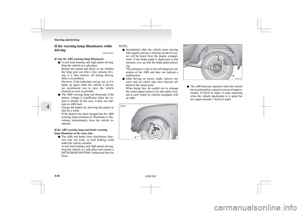
l After driving on snowy roads, remove any
snow and ice which may have become ad-
hered to the wheel areas.
When doing this, be careful not to damage
the wheel speed sensors (A) and cables loca-
ted at each wheel on vehicles equipped with
an ABS.
Front
Rear l
The ABS becomes operative after the vehicle
has
accelerated to a speed in excess of approx-
imately 10 km/h (6 mph). It stops operating
when the vehicle decelerates to a speed be-
low approximately 7 km/h (4 mph). Starting and driving
4-46
4
OCRE12E1
Page 272 of 369
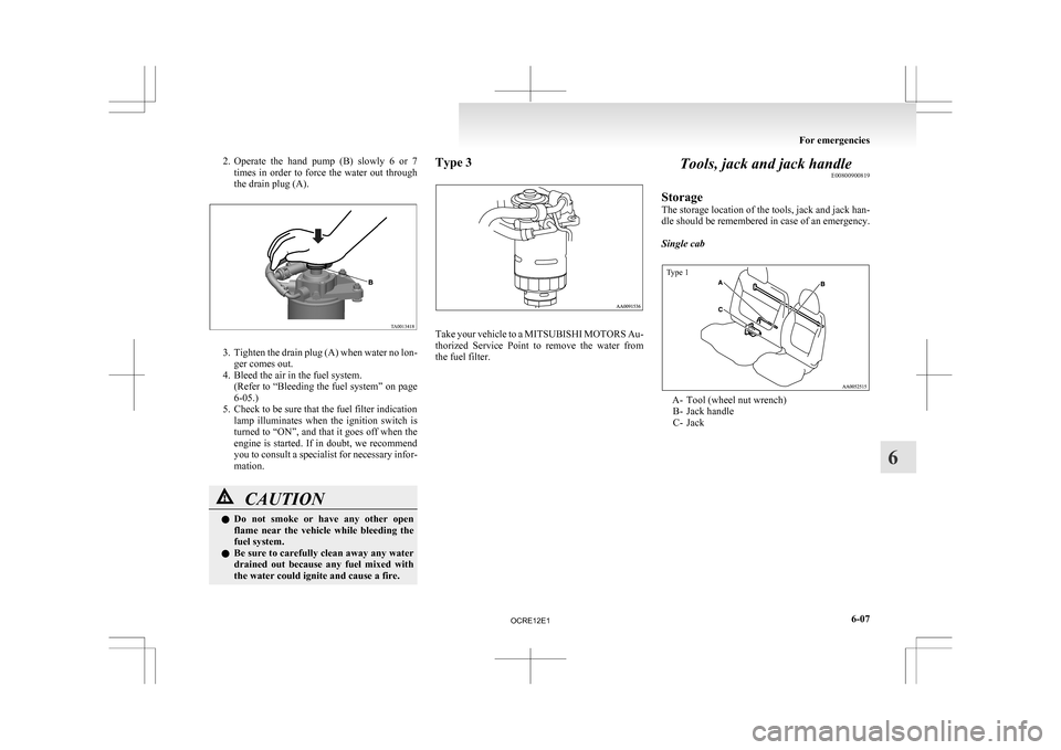
2. Operate the hand pump (B) slowly 6 or 7
times in order to force the water out through
the drain plug (A). 3. Tighten
the drain plug (A) when water no lon-
ger comes out.
4. Bleed the air in the fuel system. (Refer to “Bleeding the fuel system” on page
6-05.)
5. Check to be sure that the fuel filter indication lamp illuminates when the ignition switch is
turned to “ON”, and that it goes off when the
engine is started. If in doubt, we recommend
you to consult a specialist for necessary infor-
mation. CAUTION
l
Do
not smoke or have any other open
flame near the vehicle while bleeding the
fuel system.
l Be sure to carefully clean away any water
drained out because any fuel mixed with
the water could ignite and cause a fire. Type 3
Take your vehicle to a MITSUBISHI MOTORS
Au-
thorized Service Point to remove the water from
the fuel filter. Tools, jack and jack handle
E00800900819
Storage
The
storage location of the tools, jack and jack han-
dle should be remembered in case of an emergency.
Single cab
Type 1 A- Tool (wheel nut wrench)
B-
Jack handle
C- Jack For emergencies
6-07 6
OCRE12E1
Page 273 of 369
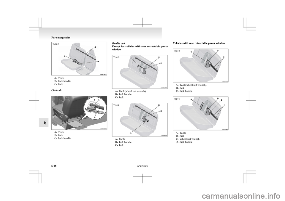
Type 2A- Tools
B-
Jack handle
C- Jack
Club cab A- Tools
B-
Jack
C- Jack handle Double cab
Except
for vehicles with rear retractable power
window
Type 1 A- Tool (wheel nut wrench)
B-
Jack handle
C- Jack
Type 2 A- Tools
B-
Jack handle
C- Jack Vehicles with rear retractable power window
Type 1
A- Tool (wheel nut wrench)
B-
Jack
C- Jack handle
Type 2 A- Tools
B-
Jack
C- Wheel nut wrench
D- Jack handle For emergencies
6-08
6
OCRE12E1
Page 274 of 369
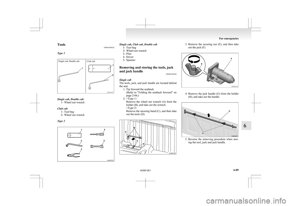
Tools
E00801900382
Type 1Single cab, Double cab Club cabSingle cab, Double cab
1-
Wheel nut wrench
Club cab 1- Tool bag
2- Wheel nut wrench
Type 2 Single cab, Club cab, Double cab
1-
Tool bag
2- Wheel nut wrench
3- Plier
4- Driver
5- Spanner
Removing and storing the tools, jack
and jack handle E00802300240
Single cab
The
tools, jack, and jack handle are located behind
the seat. 1. Tip forward the seatback.(Refer to “Folding the seatback forward” on
page 2-06.)
2.
holder (B), and take out the wrench.
Remove the securing band (C), and then take
out the tools (D). 3. Remove
the securing nut (E), and then take
out the jack (F). 4. Remove
the jack handle (G) from the holder
(H), and take out the handle. 5. Reverse
the removing procedure when stor-
ing the tool, jack and jack handle. For emergencies
6-09 6
OCRE12E1
Page 275 of 369
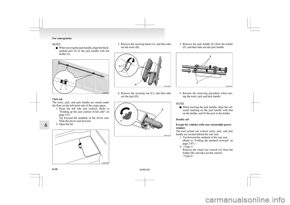
NOTE
l When
stowing the jack handle, align the black-
marked part (I) of the jack handle with the
holder (J). Club cab
The
tools, jack, and jack handle are stored under
the floor on the left-hand side of the cargo space. 1. Raise the left side seat cushion. Refer to“Folding up the seat cushion (Club cab)” on
page 2-07.
Tip forward the seatback of the driver seat.
Slide the driver seat forward.
2. Open the lid. 3. Remove
the securing band (A), and then take
out the tools (B). 4. Remove
the securing nut (C), and then take
out the jack (D). 5. Remove
the jack handle (E) from the holder
(F), and then take out the jack handle. 6. Reverse
the removing procedure when stor-
ing the tools, jack and jack handle.
NOTE l When stowing the jack handle, align the col-
oured marking on the jack handle with that
on the holder, and fit the jack in the holder.
Double cab
Except for vehicles with rear retractable power
window
The tool (wheel nut wrench only), jack, and jack
handle are located behind the rear seat. 1. Tip forward the seatback of the rear seat.(Refer to “Folding the seatback forward” on
page 2-07.)
2.
holder (B), and take out the wrench.
6-10
6
OCRE12E1
Page 276 of 369
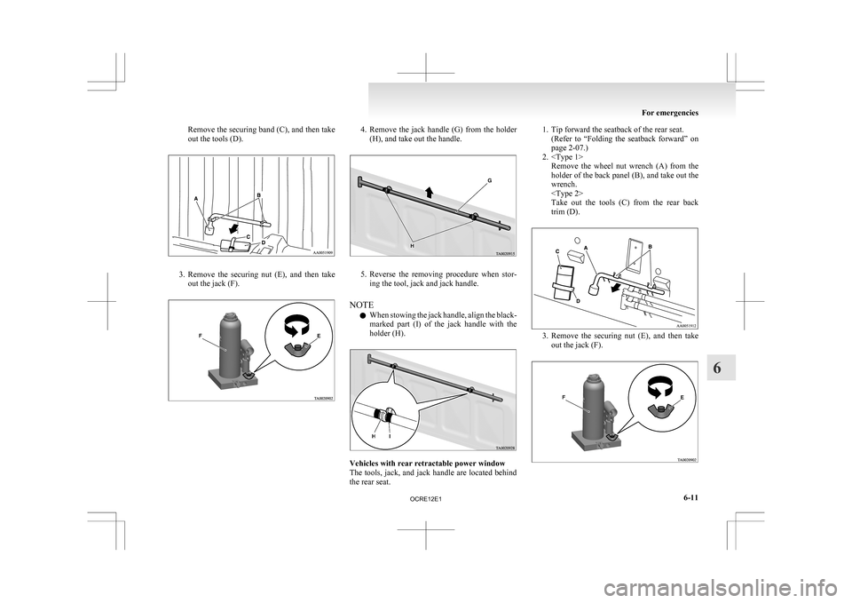
Remove the securing band (C), and then take
out the tools (D).
3. Remove the securing nut (E), and then take
out the jack (F). 4. Remove
the jack handle (G) from the holder
(H), and take out the handle. 5. Reverse
the removing procedure when stor-
ing the tool, jack and jack handle.
NOTE l When stowing the jack handle, align the black-
marked part (I) of the jack handle with the
holder (H). Vehicles with rear retractable power window
The
tools, jack, and jack handle are located behind
the rear seat. 1. Tip forward the seatback of the rear seat.
(Refer
to “Folding the seatback forward” on
page 2-07.)
2.
holder of the back panel (B), and take out the
wrench.
Take out the tools (C) from the rear back
trim (D). 3. Remove
the securing nut (E), and then take
out the jack (F). For emergencies
6-11 6
OCRE12E1
Page 277 of 369
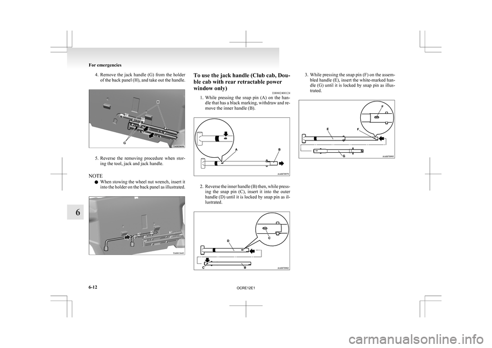
4. Remove the jack handle (G) from the holder
of the back panel (H), and take out the handle. 5. Reverse
the removing procedure when stor-
ing the tool, jack and jack handle.
NOTE l When stowing the wheel nut wrench, insert it
into the holder on the back panel as illustrated. To use the jack handle (Club cab, Dou-
ble cab with rear retractable power
window only)
E00802400124
1. While
pressing the snap pin (A) on the han-
dle that has a black marking, withdraw and re-
move the inner handle (B). 2. Reverse
the inner handle (B) then, while press-
ing the snap pin (C), insert it into the outer
handle (D) until it is locked by snap pin as il-
lustrated. 3. While
pressing the snap pin (F) on the assem-
bled handle (E), insert the white-marked han-
dle (G) until it is locked by snap pin as illus-
trated. For emergencies
6-12
6
OCRE12E1
Page 281 of 369
Spare wheel
E00801100094
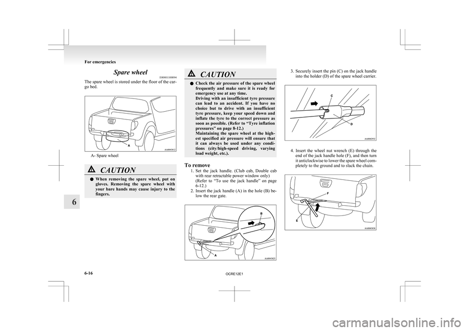
The
spare wheel is stored under the floor of the car-
go bed. A- Spare wheel
CAUTION
l
When
removing the spare wheel, put on
gloves. Removing the spare wheel with
your bare hands may cause injury to the
fingers. CAUTION
l
Check
the air pressure of the spare wheel
frequently and make sure it is ready for
emergency use at any time.
Driving with an insufficient tyre pressure
can lead to an accident. If you have no
choice but to drive with an insufficient
tyre pressure, keep your speed down and
inflate the tyre to the correct pressure as
soon as possible. (Refer to “Tyre inflation
pressures” on page 8-12.)
Maintaining the spare wheel at the high-
est specified air pressure will ensure that
it can always be used under any condi-
tions (city/high-speed driving, varying
load weight, etc.).
To remove 1. Set
the jack handle. (Club cab, Double cab
with rear retractable power window only)
(Refer to “To use the jack handle” on page
6-12.)
2. Insert the jack handle (A) in the hole (B) be- low the rear gate. 3. Securely
insert the pin (C) on the jack handle
into the holder (D) of the spare wheel carrier. 4. Insert
the wheel nut wrench (E) through the
end of the jack handle hole (F), and then turn
it anticlockwise to lower the spare wheel com-
pletely to the ground and to slack the chain. For emergencies
6-16
6
OCRE12E1