height MITSUBISHI L200 2011 (in English) User Guide
[x] Cancel search | Manufacturer: MITSUBISHI, Model Year: 2011, Model line: L200, Model: MITSUBISHI L200 2011Pages: 330, PDF Size: 22.34 MB
Page 67 of 330

Key of letters to be inserted in the table above:l U- Suitable for “universal” category restraints approved for use in this mass group.
l UF- Suitable for forward-facing “universal” category restraints approved for use in this mass group.
l L- Suitable for particular child restraints in the following list (MITSUBISHI MOTORS genuine parts).
l X- Seat position not suitable for children in this mass group.L (Genuine part information) Genuine parts No.ECE No.*2MZ312807E1-04301146*3MZ314451E1-04301203*4MZ313045E1-04301133*5MZ314250E1-04301169CAUTIONl
When installing a child restraint system, prevent the head restraint from touching the child restraint system by removing it or adjusting its height.
NOTE
l There is no applicable MITSUBISHI MOTORS Genuine Parts to the Mass Group “0-Up to 10 kg”.
MITSUBISHI MOTORS Europe B.V. reserves the right to changes without any prior announcement.
For further information, please contact a MITSUBISHI MOTORS Authorized Service Point.
Seat and seat belts
2-21
2
Page 68 of 330

Double cab
Mass group
Seating positionFront passengerRear outboardRear centreActivated airbagDeactivated airbag*10- Up to 10 kgXUUX0+- Up to 13 kgXU, L*2U, L*2XI-9 to 18 kgUF, L* 3
, L* 4U, L* 3
, L* 4U, L* 3
, L* 4L*4II-15 to 25 kgUF, L* 5U, L*5U, L*5L*5III-22 to 36 kgUF, L* 5U, L*5U, L*5L*5
*1
: With front passenger’s airbag deactivated by means of front passenger’s airbag ON-OFF switch.
Key of letters to be inserted in the table above:
l U- Suitable for “universal” category restraints approved for use in this mass group.
l UF- Suitable for forward-facing “universal” category restraints approved for use in this mass group.
l L- Suitable for particular child restraints in the following list (MITSUBISHI MOTORS genuine parts).
l X- Seat position not suitable for children in this mass group.
L (Genuine part information) Genuine parts No.ECE No.*2MZ312807E1-04301146*3MZ314451E1-04301203*4MZ313045E1-04301133*5MZ314250E1-04301169CAUTIONl
When installing a child restraint system, prevent the head restraint from touching the child restraint system by removing it or adjusting its height.
Seat and seat belts
2-22
2
Page 127 of 330
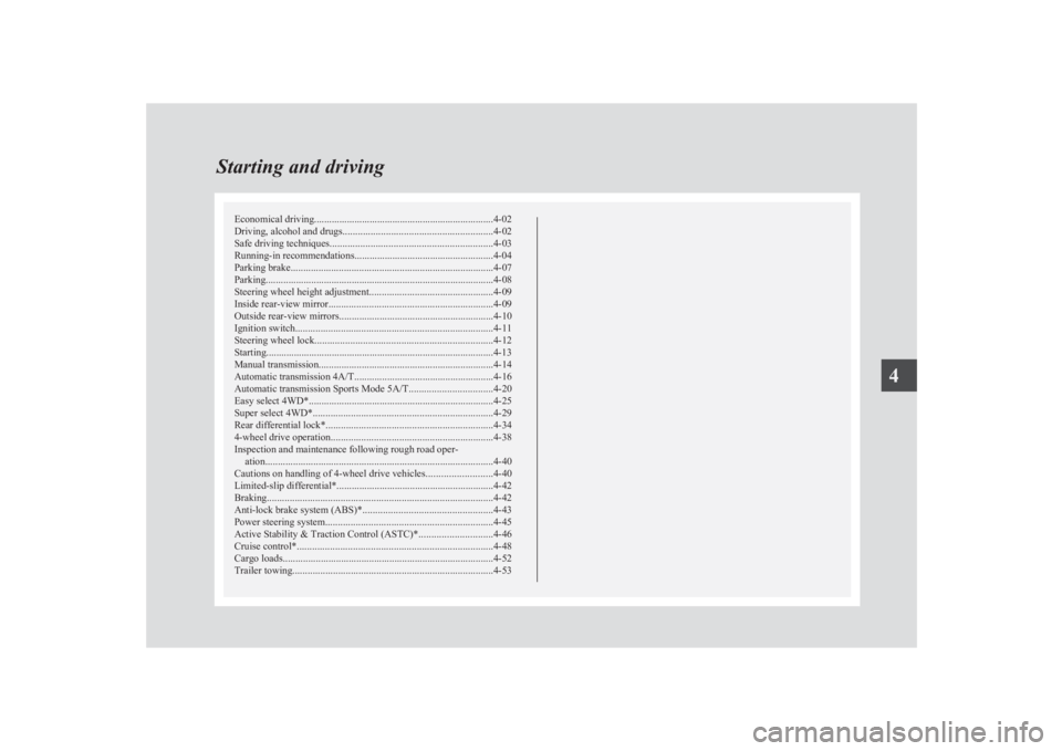
Economical driving.......................................................................4-02
Driving, alcohol and drugs ........................................................... 4-02
Safe driving techniques ................................................................ 4-03
Running-in recommendations.......................................................4-04
Parking brake ................................................................................ 4-07
Parking .......................................................................................... 4-08
Steering wheel height adjustment .................................................4-09
Inside rear-view mirror ................................................................. 4-09
Outside rear-view mirrors ............................................................. 4-10
Ignition switch .............................................................................. 4-11
Steering wheel lock ...................................................................... 4-12
Starting..........................................................................................4-13
Manual transmission ..................................................................... 4-14
Automatic transmission 4A/T ....................................................... 4-16
Automatic transmission Sports Mode 5A/T .................................4-20
Easy select 4WD* ......................................................................... 4-25
Super select 4WD* ....................................................................... 4-29
Rear differential lock* .................................................................. 4-34
4-wheel drive operation ................................................................ 4-38
Inspection and maintenance following rough road oper- ation .......................................................................................... 4-40
Cautions on handling of 4-wheel drive vehicles ..........................4-40
Limited-slip differential* .............................................................. 4-42
Braking ......................................................................................... 4-42
Anti-lock brake system (ABS)* ................................................... 4-43
Power steering system .................................................................. 4-45
Active Stability & Traction Control (ASTC)* .............................4-46
Cruise control* ............................................................................. 4-48
Cargo loads ................................................................................... 4-52
Trailer towing ............................................................................... 4-53Starting and driving4
Page 135 of 330

Steering wheel height adjustmentE00600700219
To adjust the steering wheel height, release the tilt
lock lever while holding the steering wheel by
hand, and raise or lower the steering wheel to the
desired height.
After adjustment, securely lock the lever by pulling
it upward.
1- Locked
2- Release
WARNINGl After adjusting to the desired height,
check to be sure that the lever is locked.
l Do not attempt to adjust the steering
wheel while you are driving the vehicle.
l When releasing the tilt lock lever, move it
to the release position (2) and hold the
steering wheel by hand to prevent it fall-
ing to the lowest position.Inside rear-view mirror E00600800106
Adjust the rear-view mirror only after making any
seat adjustments so you have a clear view to the
rear of the vehicle.WARNINGl Do not attempt to adjust the rear-view
mirror while driving. This can be danger-
ous.
Always adjust the mirror before driving.
Adjust the rear-view mirror to maximize the view
through the rear window.
To adjust the vertical mirror position
It is possible to move the mirror up and down to ad-
just its position.
To reduce the glare
The lever (A) at the bottom of the mirror can be
used to adjust the mirror to reduce the glare from
the headlamps of vehicles behind you during night
driving.
1- Normal
2- Anti-glare
Starting and driving
4-09
4
Page 169 of 330
WARNINGlDo not leave any objects near the brake
pedal or let a floor mat slide under it; do-
ing so could prevent the full pedal stroke
that would be necessary in an emergency.
Make sure that the pedal can be operated
freely at all times. Make sure the floor
mat is securely held in place.
Brake pads and linings
l Avoid hard braking situations.
New brakes need to be broken-in by moder-
ate use for the first 200 km (124 miles).
l The disc brakes are provided with a warning
device which emits a shrieking metallic
sound while braking if the brake pads have
reached their wear limit.
If you hear this sound, have the brake pads re-
placed immediately.
WARNINGl Driving with worn brake pads will make
it harder to stop, and can cause an acci-
dent.Anti-lock brake system (ABS)* E00607100775
Environmental conditions can have an effect on
braking. During sudden braking when there is
snow, ice, oil, water etc. on the road surface, a skid
may occur. In this situation, steering control and
braking effectiveness is reduced and the stopping
distance is increased. The vehicle may also go into
an uncontrolled spin.
The ABS helps prevent the wheels from locking dur-
ing braking, thus maintaining directional stability,
ensuring controllability and providing optimum
braking force.
Driving hints l With ABS fitted, steering during sudden brak-
ing (when the ABS functions) differs slightly
from when the brakes are not being applied.
Steer the vehicle carefully in these conditions.
l Always maintain the same distance from the
vehicle in front of you as you would for a ve-
hicle not equipped with ABS.
Compared with vehicles not fitted with ABS,
your vehicle may require a longer stopping
distance in the following cases: • Driving on gravel or snow-covered roads.
• Driving with tyre chains installed.
• Driving on roads where the road surface
is pitted or has other differences in sur-
face height.
• Driving on bumpy roads or other poor driv-
ing surfaces.l Operation of ABS is not restricted to situa-
tions where brakes are applied suddenly.
This system may also operate to prevent
wheel lock when you are driving over man-
holes, steel road-work plates, or the vehicle
is driven over steps or level differences in
the road, road markings, or other surfaces
which are difficult for the wheels to grip.
l When the ABS is activated, you may feel the
brake pedal pulsation and hear a characteris-
tic noise. Also at this time, you may feel as if
the pedal attempts to resist being depressed.
In this situation, to let the ABS work for
you, just hold the brake pedal down more
firmly. Do not pump the brake. This pump-
ing will result in reduced braking perform-
ance.CAUTIONl Even the ABS cannot prevent the natural
laws of physics from acting on the vehi-
cle. It cannot for instance avoid accidents
that may result from excessive speed on
bends or following another vehicle too
closely or aquaplaning. It should remain
the driver’s task to observe safety precau-
tions to judge speeds and brake applica-
tions correctly in such conditions.
l Be sure to use tyres of the same type and
size on 4 wheels.
If tyre types or sizes are mixed, ABS may
not function normally.
Starting and driving
4-43
4
Page 277 of 330

Before fitting tyre chains, we recommend you to
consult a MITSUBISHI MOTORS Authorized Serv-
ice Point. The max. chain height is as follows.Tyre sizeWheel sizeMax. chain
height [mm]195R15C15x6.0 JJ
22
205R16C16x6.0 JJ205/80R1616x6.0 JJ245/70R1616x7.0 J245/65R1717x7.5 J
The speed limit for tyre chain is 50 km/h (30 mph)
and remove the tyre chains as soon as possible on
snow free roads.
WARNINGl DO NOT use a jack when fitting the
chains, as in thsee conditions, the tyres
may slip on the icy road causing the vehi-
cle to slip off the jack.CAUTIONl Practice fitting the chains before you
need them.
Don’t expect help from other people in
the cold.
l Choose a clear straight stretch of road
where you can pull over and still be seen
while you are fitting the chains.
l Do not fit chains before you need them.
This will wear out your tyres and the
road surface.CAUTIONl After driving around 100-300 metres
,
stop and retighten the chains.
l Drive carefully and do not exceed
50 km/h (30 mph). Remember, fitting
chains is not going to stop accidents from
happening.
l When tyre chains are installed, take care
that they do not damage the disc wheel or
body.
l An aluminium wheel can be damaged by
a tyre chain while driving. When fitting a
tyre chain on an aluminium wheel, take
care that any part of the chain and fitting
cannot be brought into contact with the
wheel.
l When installing or removing the tyre
chains, take care that hands and other
parts of your body are not injured by the
sharp edges of the vehicle body.
l Install the chains only on the rear tyres
and tighten them as tightly as possible
with the ends securely fastened.
NOTE
l The laws and regulations concerning the use
of tyre chains vary. Find out and follow the
laws and regulations of the area you’re driv-
ing in.
In most countries, it is prohibited by law to
use tyre chains on roads without snow.
Clutch pedal free play* E01002200222
Press down the clutch pedal with your fingers until
initial resistance is felt.
This distance should be within the specified range.
A- Free play: 3 to 8 mm
If the clutch pedal free play is not within the stand-
ard range, we recommend you to have it checked.
Maintenance
8-15
8
Page 300 of 330

Single cab1Front track1,505 mm2Overall width1,750 mm3Front overhang830 mm4Wheel base3,000 mm5Rear overhang1,210 mm6Overall length5,040 mm7Ground clearance (unladen)200 mm8Overall height (unladen)1,775 mm9Rear track1,500 mm10Cargo bed length2,220 mm11Cargo bed width1,470 mm12Cargo bed height845 mm
Specifications
9-04
9
Page 302 of 330

Club cabItemEasy select 4WDSuper select 4WD1Front track1,505 mm1,520 mm2Overall width1,750 mm1,800 mm3Front overhang795 mm, 830 mm*14Wheel base3,000 mm5Rear overhangWithout rear bumper1,325 mmWith rear bumper1,400 mm6Overall lengthWithout rear bumper5,120 mm, 5,155 mm *1With rear bumper5,195 mm, 5,230 mm*17Ground clearance (unladen)200 mm205 mm8Overall height (unladen)1,775 mm1,780 mm9Rear track1,500 mm1,515 mm10Cargo bed length1,805 mm11Cargo bed width1,470 mm12Cargo bed height855 mm860 mm*1
: Vehicles for Russia and Ukraine
Specifications
9-06
9
Page 304 of 330

Double cabItem2WD and Easy select 4WDSuper select 4WD1Front track1,505 mm1,520 mm2Overall width1,750 mm1,800 mm3Front overhang795 mm, 830 mm*14Wheel base3,000 mm5Rear overhangWithout rear bumper1,210 mm, 1,390 mm *1With rear bumper1,285 mm, 1,465 mm*16Overall lengthWithout rear bumper5,005 mm, 5,185 mm*1
, 5,040 mm *2
, 5.220 mm *3With rear bumper5,080 mm, 5,260 mm *1
, 5.115 mm *2
, 5.295 mm *37Ground clearance (unladen)200 mm205 mm8Overall height (unladen)1,775 mm1,780 mm9Rear track1,500 mm1,515 mm10Cargo bed length1,325 mm, 1,505 mm *111Cargo bed width1,470 mm12Cargo bed height845 mm850 mm*1
: Vehicles with long bed
*2 : Vehicles for Russia and Ukraine
*3 : Vehicles for Russia and Ukraine with long bed
Specifications
9-08
9
Page 324 of 330
Heated seats 2-06
Rear seat 2-07
Secret box 5-43
Service precaution 8-02
Side airbag system 2-35
Side turn-signal lamps Bulb capacity 8-24
Replacement 8-28
Snow tyres 8-14
Spare wheel 6-16
Spark plug 9-16
Specifications 9-02
Speedometer 3-03
Starting 4-13
Steering Power steering fluid 8-09,9-21
Power steering system 4-45
Steering wheel height adjustment 4-09
Steering wheel lock 4-12
Steering wheel remote control switch 5-28
Stop lamps Bulb capacity 8-23
Replacement 8-30
Storage spaces 5-41
Sun visors 5-35
Sunglasses holder 5-43
Sunroof 1-13 Safety mechanism 1-14
Sunshade 1-14
Switch 1-13
Super select 4WD 4-29
Supplemental restraint system 2-27 How the Supplemental Restraint System
works 2-29
Servicing 2-39
Warning lamp 2-38
T
Tachometer 3-03
Tail lamps Bulb capacity 8-24
Replacement 8-30
Tank capacity 02
Ticket holder 5-35
Tools 6-09 Storage 6-07
Towing 6-20
Trailer towing 4-53
Transfer oil 9-21
Transmission Automatic transmission 4A/T 4-16
Automatic transmission Sports Mode 5A/
T 4-20
Fluid 8-06,9-21
Manual transmission 4-14
Specifications 9-15
Tripmeter 3-03
Turn-signal indication lamps 3-07
Turn-signals lever 3-33
Tyres 8-11 How to change a tyre 6-17
Inflation pressures 8-12
Rotation 8-13
Size (tyre and wheel) 9-17
Snow tyres 8-14
Tyre chains 8-14
Wheel condition 8-13
U
Used engine oils safety instructions and disposal in-
formation 05
Utility box 5-43
V
Vanity mirror 5-36
Vehicle care precautions 7-02
Vehicle dimensions 9-03
Vehicle identification number 9-02
Vehicle identification number plate 9-02
Vehicle information code plate 9-02
Vehicle labeling 9-02
Vehicle performance 9-09
Vehicle weight 9-10
Ventilators 5-02
W
Warning lamps 3-08
Washer Fluid 8-07,9-21
Switch 3-36,3-39
Washing 7-03
Water temperature gauge 3-05
Waxing 7-04
Weatherstripping 8-19
Weight 9-10
Wheel condition 8-13
Wheel Specification 9-17
Wiper Switch 3-36
Wiper blade rubber replacement 8-17
Wiper blades 8-17
Alphabetical index
4