check engine MITSUBISHI L200 2011 (in English) Owner's Guide
[x] Cancel search | Manufacturer: MITSUBISHI, Model Year: 2011, Model line: L200, Model: MITSUBISHI L200 2011Pages: 330, PDF Size: 22.34 MB
Page 236 of 330
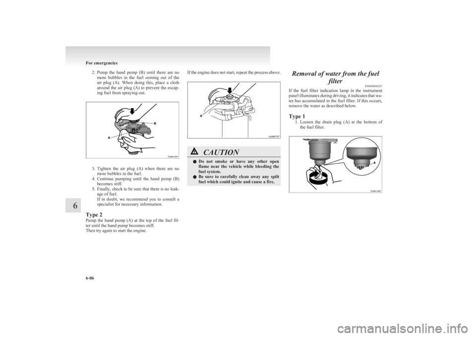
2.Pump the hand pump (B) until there are no
more bubbles in the fuel coming out of the
air plug (A). When doing this, place a cloth
around the air plug (A) to prevent the escap-
ing fuel from spraying out.
3. Tighten the air plug (A) when there are no
more bubbles in the fuel.
4. Continue pumping until the hand pump (B)
becomes stiff.
5. Finally, check to be sure that there is no leak- age of fuel.
If in doubt, we recommend you to consult a
specialist for necessary information.
Type 2
Pump the hand pump (A) at the top of the fuel fil-
ter until the hand pump becomes stiff.
Then try again to start the engine.
If the engine does not start, repeat the process above.CAUTIONl Do not smoke or have any other open
flame near the vehicle while bleeding the
fuel system.
l Be sure to carefully clean away any spilt
fuel which could ignite and cause a fire.Removal of water from the fuel
filterE00800800267
If the fuel filter indication lamp in the instrument
panel illuminates during driving, it indicates that wa-
ter has accumulated in the fuel filter. If this occurs,
remove the water as described below.
Type 1 1.Loosen the drain plug (A) at the bottom of
the fuel filter.
For emergencies
6-06
6
Page 237 of 330
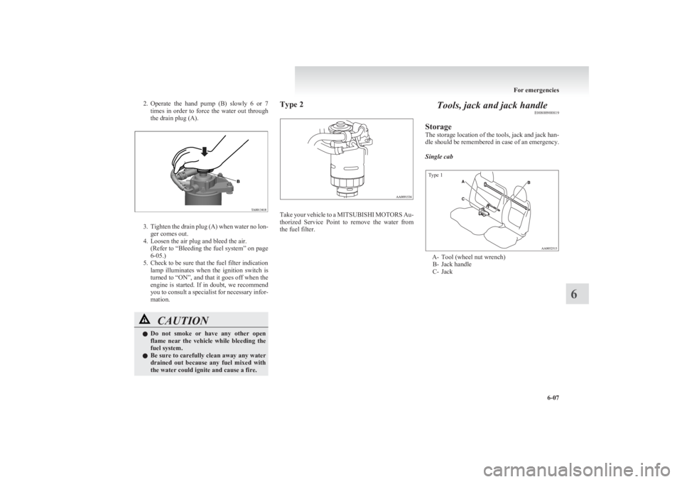
2.Operate the hand pump (B) slowly 6 or 7
times in order to force the water out through
the drain plug (A).
3. Tighten the drain plug (A) when water no lon-
ger comes out.
4. Loosen the air plug and bleed the air. (Refer to “Bleeding the fuel system” on page
6-05.)
5. Check to be sure that the fuel filter indication lamp illuminates when the ignition switch is
turned to “ON”, and that it goes off when the
engine is started. If in doubt, we recommend
you to consult a specialist for necessary infor-
mation.
CAUTIONl Do not smoke or have any other open
flame near the vehicle while bleeding the
fuel system.
l Be sure to carefully clean away any water
drained out because any fuel mixed with
the water could ignite and cause a fire.Type 2
Take your vehicle to a MITSUBISHI MOTORS Au-
thorized Service Point to remove the water from
the fuel filter.
Tools, jack and jack handle E00800900819
Storage
The storage location of the tools, jack and jack han-
dle should be remembered in case of an emergency.
Single cab
Type 1
A- Tool (wheel nut wrench) B- Jack handle
C- Jack
For emergencies
6-07
6
Page 250 of 330
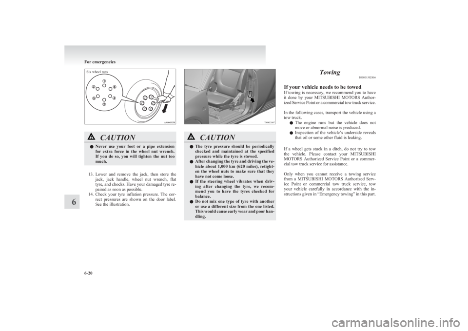
Six wheel nuts
CAUTIONlNever use your foot or a pipe extension
for extra force in the wheel nut wrench.
If you do so, you will tighten the nut too
much.
13. Lower and remove the jack, then store the
jack, jack handle, wheel nut wrench, flat
tyre, and chocks. Have your damaged tyre re-
paired as soon as possible.
14. Check your tyre inflation pressure. The cor-
rect pressures are shown on the door label.
See the illustration.
CAUTIONl The tyre pressure should be periodically
checked and maintained at the specified
pressure while the tyre is stowed.
l After changing the tyre and driving the ve-
hicle about 1,000 km (620 miles), retight-
en the wheel nuts to make sure that they
have not come loose.
l If the steering wheel vibrates when driv-
ing after changing the tyre, we recom-
mend you to have the tyres checked for
balance.
l Do not mix one type of tyre with another
or use a different size from the one listed.
This would cause early wear and poor han-
dling.Towing E00801502816
If your vehicle needs to be towed
If towing is necessary, we recommend you to have
it done by your MITSUBISHI MOTORS Author-
ized Service Point or a commercial tow truck service.
In the following cases, transport the vehicle using a
tow truck.
l The engine runs but the vehicle does not
move or abnormal noise is produced.
l Inspection of the vehicle’s underside reveals
that oil or some other fluid is leaking.
If a wheel gets stuck in a ditch, do not try to tow
the vehicle. Please contact your MITSUBISHI
MOTORS Authorized Service Point or a commer-
cial tow truck service for assistance.
Only when you cannot receive a towing service
from a MITSUBISHI MOTORS Authorized Serv-
ice Point or commercial tow truck service, tow
your vehicle carefully in accordance with the in-
structions given in “Emergency towing” in this part.
For emergencies
6-20
6
Page 264 of 330
Service precautionsE01000100706
Adequate care of your vehicle at regular intervals
serves to preserve the value and appearance as long
as possible.
Maintenance items as described in this owner’s man-
ual can be performed by the owner.
We recommend you to have the periodic inspection
and maintenance performed by a MITSUBISHI
MOTORS Authorized Service Point or another spe-
cialist.
In the event a malfunction or other problem is dis-
covered, we recommend you to have it checked
and repaired. This section contains information on
inspection maintenance procedures that you can do
yourself. Follow the instructions and cautions for
each of the various procedures.WARNINGl When checking or servicing the inside of
the engine compartment, make sure the
engine is switched off and has had a
chance to cool down.
l If it is necessary to do work in the engine
compartment with the engine running, be
especially careful that your clothing, hair,
etc., does not become caught by the fans,
drive belts, or other moving parts.
l For vehicle with air conditioning, the fan
may turn on automatically even if the en-
gine is not running; turn the ignition key
to “LOCK” position and remove the key
to ensure safety while you work in the en-
gine compartment.WARNINGl Do not smoke, cause sparks or allow open
flames around fuel or battery. The fumes
are flammable.
l Be extremely cautious when working
around the battery. It contains poisonous
and corrosive sulphuric acid.
l Do not get under your vehicle with just
the body jack supporting it. Always use
automotive jack stands.
l Improper handling of components and
materials used in the vehicle can endan-
ger your personal safety. We recommend
you to consult a specialist for necessary in-
formation.Catalytic converter E01000200925
For ordinary use, there are no particular precautions.
The exhaust gas scavenging devices used with the
catalytic converter are extremely efficient for the re-
duction of noxious gases. The catalytic converter is
installed in the exhaust system.
It is important to keep the engine properly tuned to
ensure proper catalyst operation and prevent possi-
ble catalyst damage.CAUTIONl Damage to the catalytic converter can re-
sult if your vehicle is not kept in proper
operating condition. In the event of an en-
gine malfunction particularly involving
engine misfire or other apparent loss of
performance, have your vehicle serviced
promptly.
Continued operation of your vehicle with
a severe overheated condition may result
in possible damage to the converter and
vehicle.WARNINGl As with any vehicle, do not park or oper-
ate this vehicle in areas where combusti-
ble materials such as dry grass or leaves
can come in contact with a hot exhaust
since a fire could occur.
l Paint should not be applied to the catalyt-
ic converter.
Maintenance
8-02
8
Page 266 of 330
CAUTIONlNote that the support bar may disengage
the bonnet if the open bonnet is lifted by
a strong wind.
l Always insert the support bar into the
hole provided specifically for this pur-
pose. Supporting the bonnet at any other
location could result in the support bar
slipping out and lead to an accident.
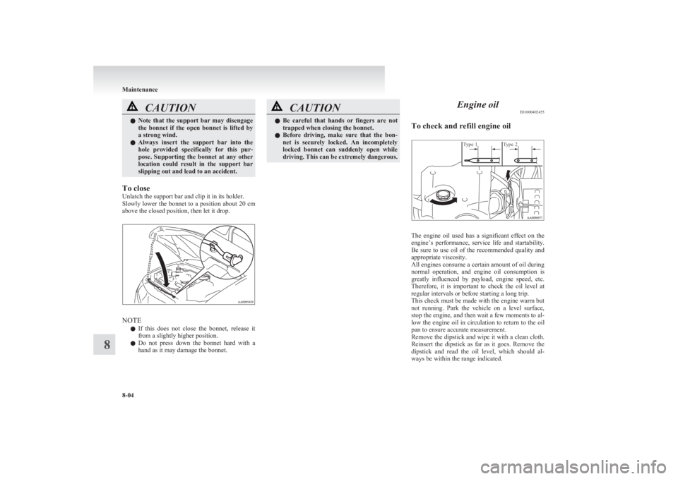
To close
Unlatch the support bar and clip it in its holder.
Slowly lower the bonnet to a position about 20 cm
above the closed position, then let it drop.
NOTE
l If this does not close the bonnet, release it
from a slightly higher position.
l Do not press down the bonnet hard with a
hand as it may damage the bonnet.
CAUTIONl Be careful that hands or fingers are not
trapped when closing the bonnet.
l Before driving, make sure that the bon-
net is securely locked. An incompletely
locked bonnet can suddenly open while
driving. This can be extremely dangerous.Engine oil E01000402455
To check and refill engine oil
Type 1Type 2
The engine oil used has a significant effect on the
engine’s performance, service life and startability.
Be sure to use oil of the recommended quality and
appropriate viscosity.
All engines consume a certain amount of oil during
normal operation, and engine oil consumption is
greatly influenced by payload, engine speed, etc.
Therefore, it is important to check the oil level at
regular intervals or before starting a long trip.
This check must be made with the engine warm but
not running. Park the vehicle on a level surface,
stop the engine, and then wait a few moments to al-
low the engine oil in circulation to return to the oil
pan to ensure accurate measurement.
Remove the dipstick and wipe it with a clean cloth.
Reinsert the dipstick as far as it goes. Remove the
dipstick and read the oil level, which should al-
ways be within the range indicated.
Maintenance
8-04
8
Page 267 of 330
If the oil level is below the specified limit, remove
the cap located on the cylinder head cover and add
enough oil to raise the level to within the specified
range.
Be sure to use the specified engine oil and do not
mix various types of oil. Also, avoid mixing differ-
ent makes of oil together if possible.
After adding oil, close the cap securely.
Use only the recommended oils with an ACEA or
API classification as specified in this manual.
NOTE l The engine oil will deteriorate rapidly if the
vehicle is subjected to severe conditions (for
example, repeated operation on rough roads,
in mountainous regions, on roads with many
uphill and downhill gradients, or over short
distances). Consequently, the oil will require
earlier replacement.
l For handling of used engine oils, refer to
page 05.
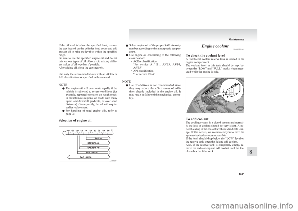
Selection of engine oill Select engine oil of the proper SAE viscosity
number according to the atmospheric temper-
ature.
l Use engine oil conforming to the following
classification: • ACEA classification:“For service A1/ B1, A3/B3, A3/B4,
A5/B5”
• API classification: “For service CF-4”
NOTE l Use of additives is not recommended since
they may reduce the effectiveness of addi-
tives already included in the engine oil. It
may result in failure of the mechanical assem-
bly.Engine coolant E01000501202
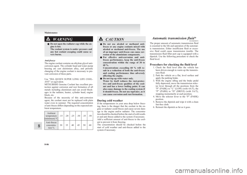
To check the coolant level
A translucent coolant reserve tank is located in the
engine compartment.
The coolant level in this tank should be kept be-
tween the “LOW” and “FULL” marks when meas-
ured while the engine is cold.
To add coolant
The cooling system is a closed system and normal-
ly the loss of coolant should be very slight. A no-
ticeable drop in the coolant level could indicate leak-
age. If this occurs, we recommend you to have the
system checked as soon as possible.
If the level should drop below the “LOW” level on
the reserve tank, open the lid and add coolant.
Also, if the reserve tank is completely empty, re-
move the radiator cap and add coolant until the lev-
el reaches the filler neck.
Maintenance
8-05
8
Page 268 of 330
WARNINGlDo not open the radiator cap while the en-
gine is hot.
The coolant system is under pressure and
any hot coolant escaping could cause se-
vere burns.
Anti-freeze
The engine coolant contains an ethylene glycol anti-
corrosion agent. The cylinder head and water pump
housing are cast aluminium alloy, and periodic
changing of the engine coolant is necessary to pre-
vent corrosion of these parts.
Use “DIA QUEEN SUPER LONG LIFE COOL-
ANT” or equivalent.
MITSUBISHI Genuine Coolant has excellent pro-
tection against corrosion and rust formation of all
metals including aluminium and can avoid block-
ages in the radiator, heater, cylinder head, engine
block, etc.
Because of the necessity of this anti-corrosion
agent, the coolant must not be replaced with plain
water even in summer. The required concentration
of anti-freeze differs depending on the expected am-
bient temperature.
Ambient
temperature
( minimum) °C-15-20-25-30-35-50Anti-freeze
concentra- tion %303540455060CAUTIONl Do not use alcohol or methanol anti-
freeze or any engine coolants mixed with
alcohol or methanol anti-freeze. The use
of an improper anti-freeze can cause cor-
rosion of the aluminium components.
l For effective anti-corrosion and anti-
freeze performance, keep the anti-freeze
concentration within the range of 30 to
60 %.
Concentrations exceeding 60 % will re-
sult in a reduction of both the anti-freeze
and cooling performance thus adversely
affecting the engine.
l Do not top up with water only.
Water by itself reduces the rust-protec-
tive and anti-freeze qualities of the cool-
ant and has a lower boiling point. It can
also cause damage to the cooling system if
it should freeze. Do not use tapwater, as it
can cause corrosion and rust formation.
During cold weather
If the temperatures in your area drop below freez-
ing, there is the danger that the coolant in the en-
gine or radiator could freeze and cause severe dam-
age to the engine and/or radiator. The concentra-
tion should be checked before the start of cold weath-
er and anti-freeze added to the system if necessary.
Add a sufficient amount of anti-freeze to the cool-
ant to prevent it from freezing.
The concentration should be checked before the
start of cold weather and anti-freeze added to the
system if necessary.
Automatic transmission fluid* E01000600974
The proper amount of automatic transmission fluid
is essential to the life and operation of the automat-
ic transmission. Either insufficient fluid or exces-
sive fluid could cause transmission trouble. The
transmission fluid filler port cap is equipped with a
dipstick. Use the following procedure to check the
fluid level.
Procedure for checking the fluid level 1.Check the fluid level after the vehicle has
been driven enough to warm up the transmis-
sion fluid.
2. Park the vehicle on a flat, level surface and
apply the parking brake.
3. With the engine idling and the brake pedal
fully depressed, move the transmission selec-
tor lever through all the positions from the
"P” (PARK) to “L” (LOW) (with 4A/T), the
“P” (PARK) to “D” (DRIVE) (with 5A/T),
stopping momentarily at each position.
4. Move the selector lever to the “P” (PARK)
position.
5. Remove the dipstick and wipe it with a clean
lint-free cloth.
6. Reinsert the dipstick as far as it goes.
Maintenance
8-06
8
Page 271 of 330
Power steering fluidE01001100703
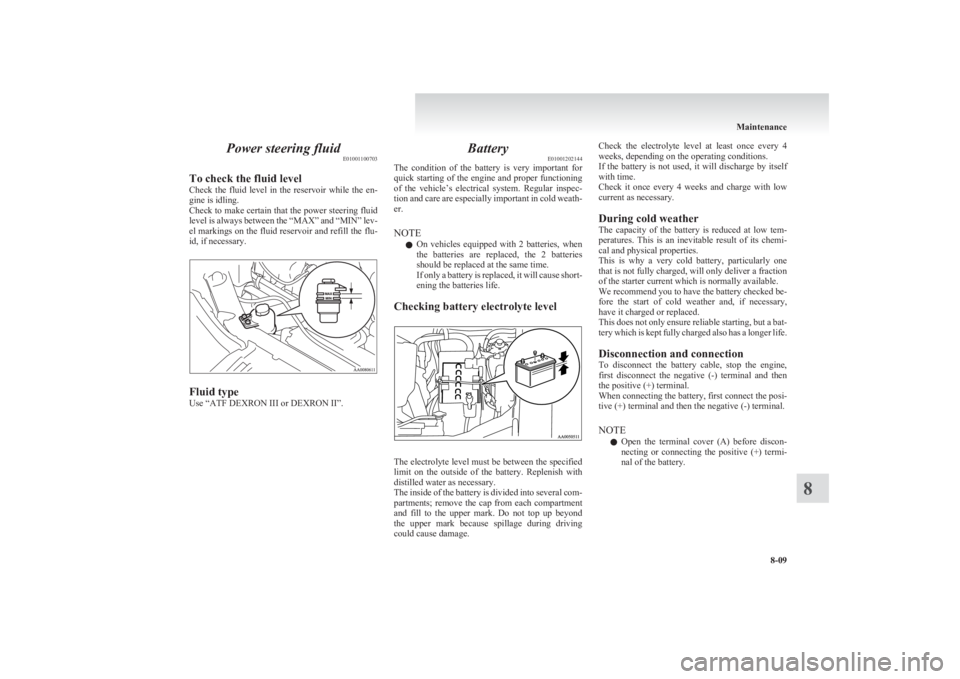
To check the fluid level
Check the fluid level in the reservoir while the en-
gine is idling.
Check to make certain that the power steering fluid
level is always between the “MAX” and “MIN” lev-
el markings on the fluid reservoir and refill the flu-
id, if necessary.
Fluid type
Use “ATF DEXRON III or DEXRON II”.
Battery E01001202144
The condition of the battery is very important for
quick starting of the engine and proper functioning
of the vehicle’s electrical system. Regular inspec-
tion and care are especially important in cold weath-
er.
NOTE l On vehicles equipped with 2 batteries, when
the batteries are replaced, the 2 batteries
should be replaced at the same time.
If only a battery is replaced, it will cause short-
ening the batteries life.
Checking battery electrolyte level
The electrolyte level must be between the specified
limit on the outside of the battery. Replenish with
distilled water as necessary.
The inside of the battery is divided into several com-
partments; remove the cap from each compartment
and fill to the upper mark. Do not top up beyond
the upper mark because spillage during driving
could cause damage.
Check the electrolyte level at least once every 4
weeks, depending on the operating conditions.
If the battery is not used, it will discharge by itself
with time.
Check it once every 4 weeks and charge with low
current as necessary.
During cold weather
The capacity of the battery is reduced at low tem-
peratures. This is an inevitable result of its chemi-
cal and physical properties.
This is why a very cold battery, particularly one
that is not fully charged, will only deliver a fraction
of the starter current which is normally available.
We recommend you to have the battery checked be-
fore the start of cold weather and, if necessary,
have it charged or replaced.
This does not only ensure reliable starting, but a bat-
tery which is kept fully charged also has a longer life.
Disconnection and connection
To disconnect the battery cable, stop the engine,
first disconnect the negative (-) terminal and then
the positive (+) terminal.
When connecting the battery, first connect the posi-
tive (+) terminal and then the negative (-) terminal.
NOTE l Open the terminal cover (A) before discon-
necting or connecting the positive (+) termi-
nal of the battery.
Maintenance
8-09
8
Page 278 of 330
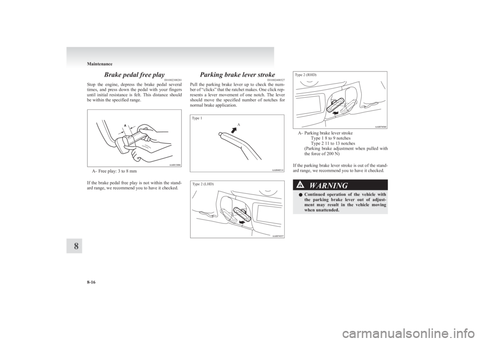
Brake pedal free playE01002300281
Stop the engine, depress the brake pedal several
times, and press down the pedal with your fingers
until initial resistance is felt. This distance should
be within the specified range.
A- Free play: 3 to 8 mm
If the brake pedal free play is not within the stand-
ard range, we recommend you to have it checked.
Parking brake lever stroke E01002400527
Pull the parking brake lever up to check the num-
ber of “clicks” that the ratchet makes. One click rep-
resents a lever movement of one notch. The lever
should move the specified number of notches for
normal brake application.
Type 1AType 2 (LHD)Type 2 (RHD)
A- Parking brake lever stroke Type 1 8 to 9 notches
Type 2 11 to 13 notches
( Parking brake adjustment when pulled with
the force of 200 N)
If the parking brake lever stroke is out of the stand-
ard range, we recommend you to have it checked.
WARNINGl Continued operation of the vehicle with
the parking brake lever out of adjust-
ment may result in the vehicle moving
when unattended.
Maintenance
8-16
8
Page 280 of 330
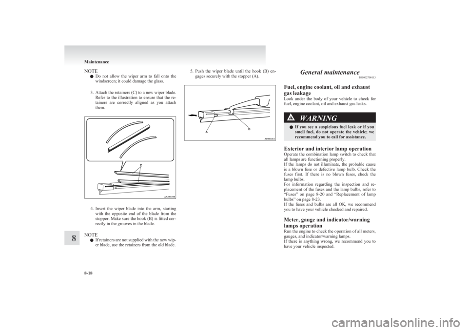
NOTEl Do not allow the wiper arm to fall onto the
windscreen; it could damage the glass.
3. Attach the retainers (C) to a new wiper blade.
Refer to the illustration to ensure that the re-
tainers are correctly aligned as you attach
them.
4. Insert the wiper blade into the arm, starting
with the opposite end of the blade from the
stopper. Make sure the hook (B) is fitted cor-
rectly in the grooves in the blade.
NOTE l If retainers are not supplied with the new wip-
er blade, use the retainers from the old blade.
5. Push the wiper blade until the hook (B) en-
gages securely with the stopper (A).General maintenance E01002700113
Fuel, engine coolant, oil and exhaust
gas leakage
Look under the body of your vehicle to check for
fuel, engine coolant, oil and exhaust gas leaks.WARNINGl If you see a suspicious fuel leak or if you
smell fuel, do not operate the vehicle; we
recommend you to call for assistance.
Exterior and interior lamp operation
Operate the combination lamp switch to check that
all lamps are functioning properly.
If the lamps do not illuminate, the probable cause
is a blown fuse or defective lamp bulb. Check the
fuses first. If there is no blown fuses, check the
lamp bulbs.
For information regarding the inspection and re-
placement of the fuses and the lamp bulbs, refer to
“ Fuses” on page 8-20 and “Replacement of lamp
bulbs” on page 8-23.
If the fuses and bulbs are all OK, we recommend
you to have your vehicle checked and repaired.
Meter, gauge and indicator/warning
lamps operation
Run the engine to check the operation of all meters,
gauges, and indicator/warning lamps.
If there is anything wrong, we recommend you to
have your vehicle inspected.
Maintenance
8-18
8