fuel cap MITSUBISHI L200 2011 Owner's Manual (in English)
[x] Cancel search | Manufacturer: MITSUBISHI, Model Year: 2011, Model line: L200, Model: MITSUBISHI L200 2011Pages: 330, PDF Size: 22.34 MB
Page 2 of 330
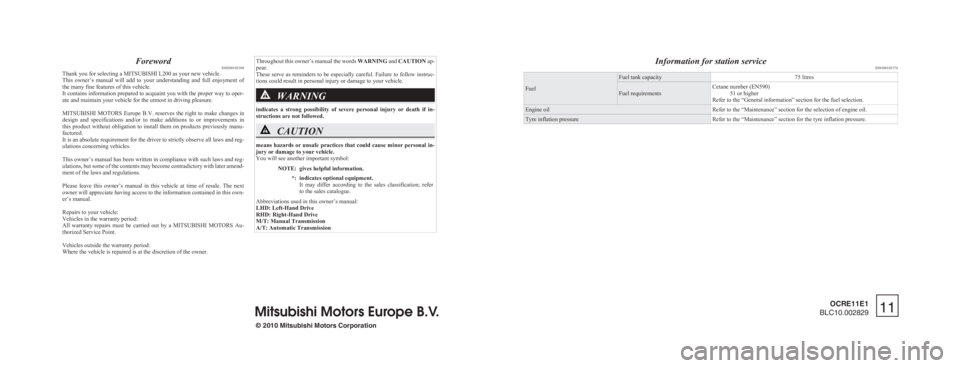
ForewordE09200103398
Thank you for selecting a MITSUBISHI L200 as your new vehicle.
This owner’s manual will add to your understanding and full enjoyment of
the many fine features of this vehicle.
It contains information prepared to acquaint you with the proper way to oper-
ate and maintain your vehicle for the utmost in driving pleasure.
MITSUBISHI MOTORS Europe B.V. reserves the right to make changes in
design and specifications and/or to make additions to or improvements in
this product without obligation to install them on products previously manu-
factured.
It is an absolute requirement for the driver to strictly observe all laws and reg-
ulations concerning vehicles.
This owner’s manual has been written in compliance with such laws and reg-
ulations, but some of the contents may become contradictory with later amend-
ment of the laws and regulations.
Please leave this owner’s manual in this vehicle at time of resale. The next
owner will appreciate having access to the information contained in this own-
er’s manual.
Repairs to your vehicle:
Vehicles in the warranty period:
All warranty repairs must be carried out by a MITSUBISHI MOTORS Au-
thorized Service Point.
Vehicles outside the warranty period:
Where the vehicle is repaired is at the discretion of the owner.
Throughout this owner’s manual the words WARNING and CAUTION ap-
pear.
These serve as reminders to be especially careful. Failure to follow instruc-
tions could result in personal injury or damage to your vehicle.WARNING
indicates a strong possibility of severe personal injury or death if in-
structions are not followed.
CAUTION
means hazards or unsafe practices that could cause minor personal in-
jury or damage to your vehicle.
You will see another important symbol:
NOTE:gives helpful information.*:indicates optional equipment.
It may differ according to the sales classification; refer
to the sales catalogue.
Abbreviations used in this owner’s manual:
LHD: Left-Hand Drive
RHD: Right-Hand Drive
M/T: Manual Transmission
A/T: Automatic Transmission
Information for station service E09300102174
Fuel
Fuel tank capacity75 litresFuel requirementsCetane number (EN590)
51 or higher
Refer to the “General information” section for the fuel selection.Engine oilRefer to the “Maintenance” section for the selection of engine oil.Tyre inflation pressureRefer to the “Maintenance” section for the tyre inflation pressure.
© 2010 Mitsubishi Motors Corporation11
OCRE11E1
BLC10.002829
Page 26 of 330
Fuel selectionE00200102141Recommended fuelCetane number (EN590)
51 or higherCAUTIONlYour vehicle is designed to use only diesel
fuel that meets the EN 590 standard.
Use of any other type of diesel fuel would
adversely affect the engine’s performance
and durability.
NOTE
l Due to the separation of paraffin, the fluidity
of the fuel decreases considerably as the tem-
perature falls.
Because of this fact there are two kinds of
fuel: “summer” and “winter”.
This must be considered in winter use.
Select either of the two kinds of fuel in ac-
cordance with ambient temperature. Above -5 °C: “Summer” diesel
Below -5 °C: “Winter” diesel
When travelling abroad, find out in advance
about the fuels served in local service stations.
l Poor-quality diesel fuel can cause deposits to
form in the injector, resulting in black smoke
and rough idling.
If these problems occur, you are advised to
add a cleaning additive to the diesel fuel
when you refuel the vehicle.
The additive will break up and remove the de-
posits, thereby returning the engine to a nor-
mal condition.
Be sure to use a genuine MITSUBISHI DIE-
SEL FUEL SYSTEM CLEANER. Using an
unsuitable additive could make the engine
malfunction. For details, please contact your
MITSUBISHI MOTORS Authorized Service
Point.Filling the fuel tank E00200202025WARNINGlWhen handling fuel, comply with the safe-
ty regulations displayed by garages and
filling stations.
l Before removing the fuel cap, be sure to
get rid of your body’s static electricity by
touching a metal part of the car or the
fuel pump. Any static electricity on your
body could create a spark that ignites
fuel vapour.
l Perform the whole refueling process
(opening the fuel tank filler door, remov-
ing the fuel cap, etc.) by yourself. Do not
let any other person come near the fuel
tank filler. If you allowed a person to
help you and that person was carrying
static electricity, fuel vapour could be ig-
nited.
l Do not move away from the fuel tank fill-
er until refueling is finished. If you
moved away and did something else (for
example, cleaning your windscreen) part-
way through the refueling process, you
could pick up a fresh charge of static elec-
tricity.
l If the tank cap must be replaced, use only
a MITSUBISHI MOTORS original part.
Fuel tank capacity
75 litres
Refueling 1. Before filling with fuel, stop the engine.
General information
02
Page 27 of 330
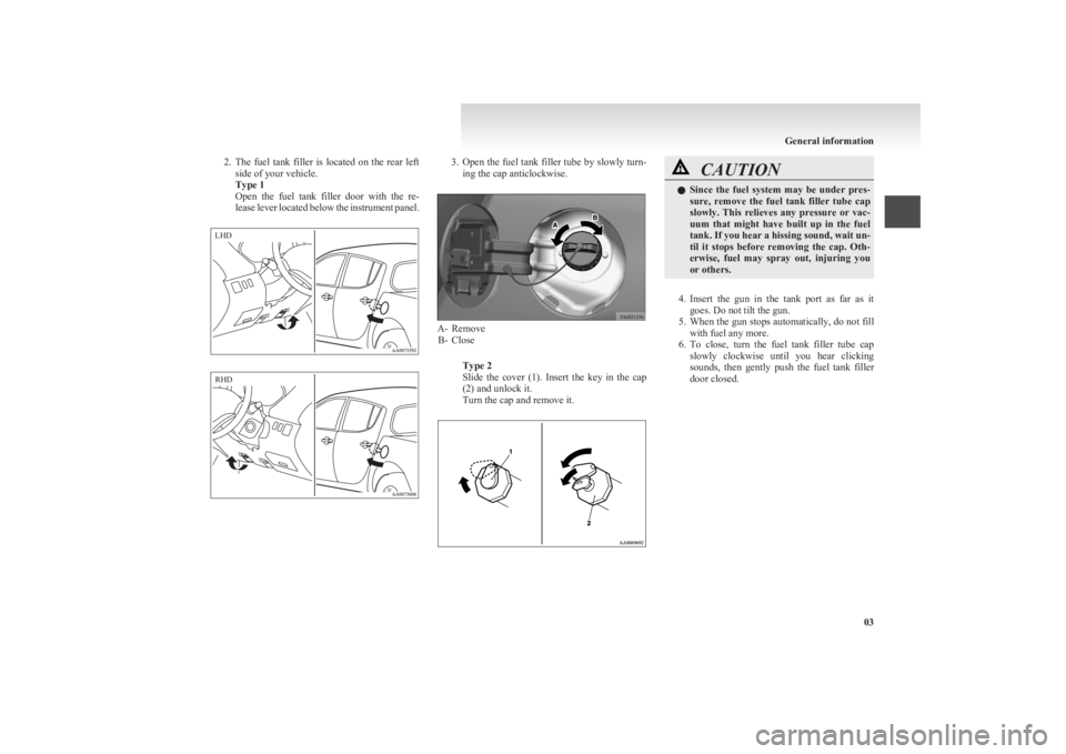
2.The fuel tank filler is located on the rear left
side of your vehicle.
Type 1
Open the fuel tank filler door with the re-
lease lever located below the instrument panel.3. Open the fuel tank filler tube by slowly turn-
ing the cap anticlockwise.
A- Remove B- Close
Type 2
Slide the cover (1). Insert the key in the cap
(2) and unlock it.
Turn the cap and remove it.
CAUTIONl Since the fuel system may be under pres-
sure, remove the fuel tank filler tube cap
slowly. This relieves any pressure or vac-
uum that might have built up in the fuel
tank. If you hear a hissing sound, wait un-
til it stops before removing the cap. Oth-
erwise, fuel may spray out, injuring you
or others.
4. Insert the gun in the tank port as far as it
goes. Do not tilt the gun.
5. When the gun stops automatically, do not fill
with fuel any more.
6. To close, turn the fuel tank filler tube cap
slowly clockwise until you hear clicking
sounds, then gently push the fuel tank filler
door closed.
General information
03LHD RHD
Page 235 of 330
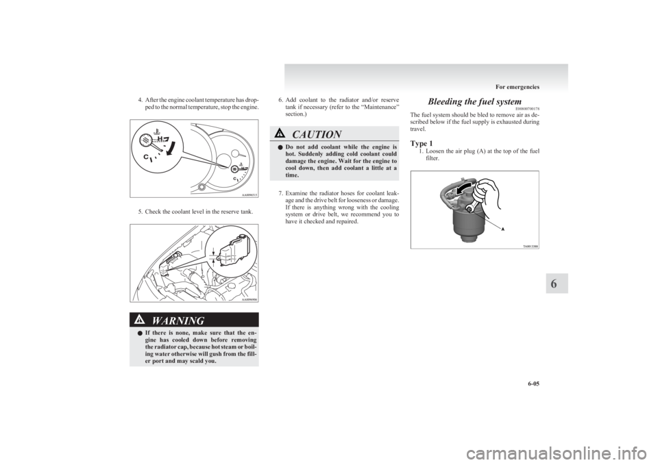
4.After the engine coolant temperature has drop-
ped to the normal temperature, stop the engine.
5. Check the coolant level in the reserve tank.
WARNINGl If there is none, make sure that the en-
gine has cooled down before removing
the radiator cap, because hot steam or boil-
ing water otherwise will gush from the fill-
er port and may scald you.6. Add coolant to the radiator and/or reserve
tank if necessary (refer to the “Maintenance”
section.)CAUTIONl Do not add coolant while the engine is
hot. Suddenly adding cold coolant could
damage the engine. Wait for the engine to
cool down, then add coolant a little at a
time.
7. Examine the radiator hoses for coolant leak-
age and the drive belt for looseness or damage.
If there is anything wrong with the cooling
system or drive belt, we recommend you to
have it checked and repaired.
Bleeding the fuel system E00800700178
The fuel system should be bled to remove air as de-
scribed below if the fuel supply is exhausted during
travel.
Type 1 1.Loosen the air plug (A) at the top of the fuel
filter.
For emergencies
6-05
6
Page 236 of 330
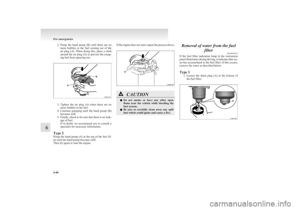
2.Pump the hand pump (B) until there are no
more bubbles in the fuel coming out of the
air plug (A). When doing this, place a cloth
around the air plug (A) to prevent the escap-
ing fuel from spraying out.
3. Tighten the air plug (A) when there are no
more bubbles in the fuel.
4. Continue pumping until the hand pump (B)
becomes stiff.
5. Finally, check to be sure that there is no leak- age of fuel.
If in doubt, we recommend you to consult a
specialist for necessary information.
Type 2
Pump the hand pump (A) at the top of the fuel fil-
ter until the hand pump becomes stiff.
Then try again to start the engine.
If the engine does not start, repeat the process above.CAUTIONl Do not smoke or have any other open
flame near the vehicle while bleeding the
fuel system.
l Be sure to carefully clean away any spilt
fuel which could ignite and cause a fire.Removal of water from the fuel
filterE00800800267
If the fuel filter indication lamp in the instrument
panel illuminates during driving, it indicates that wa-
ter has accumulated in the fuel filter. If this occurs,
remove the water as described below.
Type 1 1.Loosen the drain plug (A) at the bottom of
the fuel filter.
For emergencies
6-06
6
Page 284 of 330
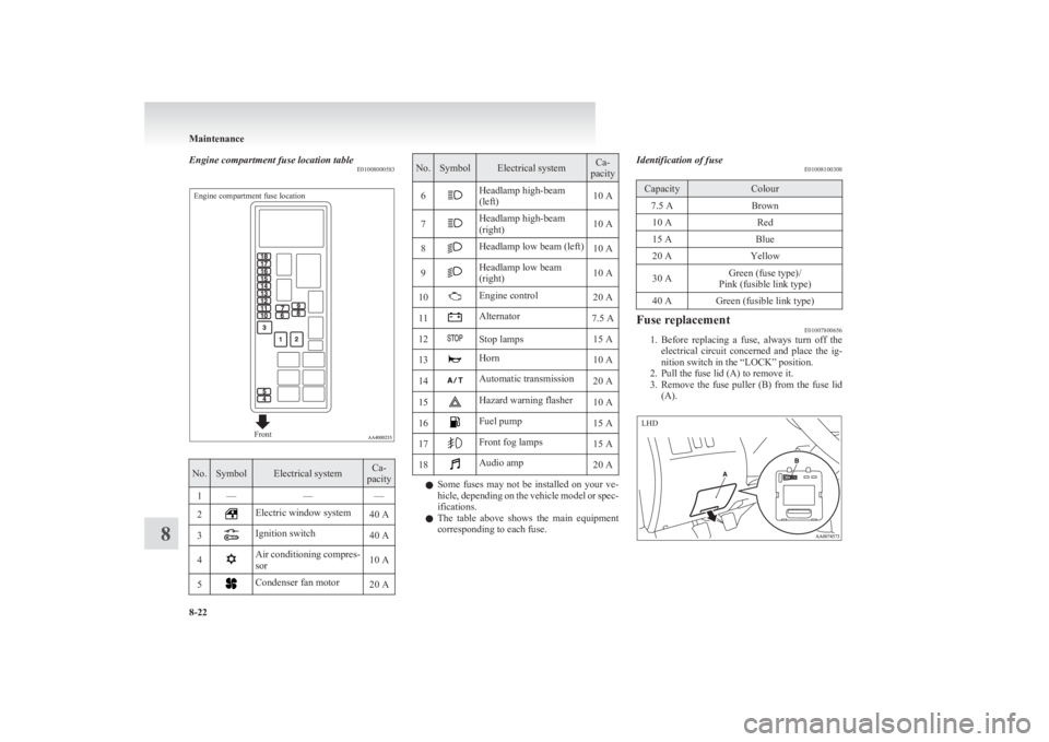
Engine compartment fuse location tableE01008000583Engine compartment fuse locationFront
No.SymbolElectrical systemCa-
pacity1———2Electric window system40 A3Ignition switch40 A4Air conditioning compres-
sor10 A5Condenser fan motor20 ANo.SymbolElectrical systemCa-
pacity6Headlamp high-beam
(left)10 A7Headlamp high-beam
(right)10 A8Headlamp low beam (left)10 A9Headlamp low beam
(right)10 A10Engine control20 A11Alternator7.5 A12Stop lamps15 A13Horn10 A14Automatic transmission20 A15Hazard warning flasher10 A16Fuel pump15 A17Front fog lamps15 A18Audio amp20 A
l Some fuses may not be installed on your ve-
hicle, depending on the vehicle model or spec-
ifications.
l The table above shows the main equipment
corresponding to each fuse.
Identification of fuse E01008100308CapacityColour7.5 ABrown10 ARed15 ABlue20 AYellow30 AGreen (fuse type)/
Pink (fusible link type)40 AGreen (fusible link type)Fuse replacement E01007800656
1.Before replacing a fuse, always turn off the
electrical circuit concerned and place the ig-
nition switch in the “LOCK” position.
2. Pull the fuse lid (A) to remove it.
3. Remove the fuse puller (B) from the fuse lid
(A).
Maintenance
8-22
8 LHD
Page 297 of 330
Vehicle labeling............................................................................ 9-02
Vehicle dimensions.......................................................................9-03
Vehicle performance.....................................................................9-09
Vehicle weight .............................................................................. 9-10
Engine specifications .................................................................... 9-14
Transmission specifications .......................................................... 9-15
Electrical system ........................................................................... 9-16
Tyres and wheels .......................................................................... 9-17
Other specifications ...................................................................... 9-18
Fuel consumption ......................................................................... 9-19
Refill capacities ............................................................................ 9-21Specifications9
Page 321 of 330
4
4-wheel drive operation 4-38A
Accessory (Installation) 04
Accessory socket 5-38
Active Stability & Traction Control (ASTC) 4-46
Additional equipment 8-19
Air conditioning Automatic air conditioning 5-08
Important operation tips for the air condition-
ing 5-12
Manual air conditioning 5-03
Air purifier 5-12
Airbag 2-27
Antenna 5-34
Anti-lock brake system (ABS) 4-43 Warning lamp 4-44
Armrest (Double cab) 2-07
Ashtray 5-36
Audio Audio system anti-theft feature 5-32
Error codes 5-30
Handling of compact discs 5-32
LW/MW/FM electronic tuning radio with CD
player 5-13
Steering wheel remote control switch 5-28
Automatic air conditioning 5-08
Automatic transmission 4A/T 4-16 Fluid 8-06,9-21
Overdrive control switch 4-17
Selector lever operation 4-16,4-20
Selector lever position 4-17
Selector lever position indicator 4-16
Automatic transmission Sports Mode 5A/T 4-20 Fluid 8-06,9-21
Selector lever operation 4-20
Selector lever position indicator 4-21
Selector lever positions 4-21
Sports mode 4-22
Sports mode indicator 4-22
B
Battery 8-09Discharged battery (Emergency starting) 6-02
Specification 9-16
Bleeding the fuel system 6-05
Bonnet 8-03
Bottle holder 5-45
Brake Anti-lock brake 4-43
Braking 4-42
Fluid 8-07,9-21
Parking brake 4-07
Parking brake lever stroke 8-16
Pedal free play 8-16
Warning lamp 3-08
C
Cargo loads 4-52
Catalytic converter 8-02
Cautions on handling of 4-wheel drive vehi-
cles 4-40
Central door locks 1-07
Centre console downlight 5-41 Bulb capacity 8-24
Replacement 8-34
Centre information display 3-10
Changing a fuse 8-22
Changing gears 4-14
Check engine warning lamp 3-08
Child restraint 2-13
Child-protection rear doors 1-08
Cigarette lighter 5-37
Cleaning Exterior of your vehicle 7-03
Genuine leather 7-02
Interior of your vehicle 7-02
Plastic, vinyl leather, etc 7-02
Sunroof 7-05
Waxing 7-04
Clock 3-19,5-39
Clutch Fluid 8-08,9-21
Pedal free play 8-15
Coat hook 5-46
Combination headlamps and dipper switch 3-30
Convenient hook 5-46
Coolant (engine) 8-05,9-21
Cruise control 4-48 Switch 4-49
Cup holder 5-44
Curtain airbag system 2-35
D
Demister (rear window) 3-40
Differential oil 9-21
Digital clock 3-19,5-39
Dimensions 9-03
Dipper (High/Low beam change) 3-31
Door courtesy lamps 5-41 Replacement 8-33
Doors Central door locks 1-07
Child-protection 1-08
Lock and unlock 1-06
Driving, alcohol and drugs 4-02
E
Easy select 4WD 4-25
Alphabetical index
1
Page 322 of 330
Economical driving 4-02
Electric window control 1-08 Switch 1-08
Electrical system 9-16
Electronic immobilizer (Anti-theft starting sys-
tem) 1-03
Emergency starting 6-02
Engine specifications 9-14
Engine Coolant 8-05,9-21
Number 9-02
Oil 8-04,9-21
Overheating 6-04
Specifications 9-14
Used engine oils safety instructions and disposal
information 05
Water temperature gauge 3-05
Error codes 5-30
Exterior and interior lamp operation 8-18
F
First-aid kit and warning triangle band for secur-
ing 5-46
Floor console box 5-42
Fluid Automatic transmission fluid 8-06,9-21
Brake fluid 8-07,9-21
Clutch fluid 8-08,9-21
Engine coolant 8-05,9-21
Power steering fluid 8-09,9-21
Washer fluid 8-07,9-21
For cold and snowy weather 8-19
Front console box 5-42
Front fog lamps Bulb capacity 8-24
Indication lamp 3-07
Replacement 8-28
Switch 3-34
Front room lamp Bulb capacity 8-25
Replacement 8-32
Front seat 2-03
Front turn-signal lamps Bulb capacity 8-24
Replacement 8-27
Fuel consumption 9-19
Fuel Filling the fuel tank 02
Fuel filter indication lamp 3-07
Fuel gauge 3-04
Fuel selection 02
Low fuel warning lamp 3-04
Modification/alterations to the electrical or fuel
systems 04
Tank capacity 02
Fuses 8-20
Fusible links 8-19
G
Gauges 3-02
General maintenance 8-18
General vehicle data 9-03
Genuine parts 05
Glove box 5-42
Glove box lamp Bulb capacity 8-24
Replacement 8-33
H
Handling of compact discs 5-32
Hazard warning flasher switch 3-34
Hazard warning indication lamps 3-07
Head restraints 2-08
Headlamp levelling switch 3-32
Headlamps
Bulb capacity 8-24
Headlamp flasher 3-31
Replacement 8-25
Switch 3-30
Washer switch 3-39
Heated mirror 4-11
Heated seats 2-06
Heater 5-03
High-mounted stop lamp Bulb capacity 8-24
Replacement 8-31
Hinges and latches lubrication 8-19
Hooks Coat hook 5-46
Convenient hook 5-46
Horn switch 3-40
I
If the vehicle breaks down 6-02
Ignition switch 4-11
Indication and warning lamps 3-06
Indication lamps 3-07
Inside rear-view mirror 4-09
Inspection and maintenance following rough road
operation 4-40
Installation of accessories 04
Instruments 3-02
Interior lamps 5-39
J
Jack handle 6-12Storage 6-07
Jacking up the vehicle 6-13
Jack Storage 6-07
Jump starting (Emergency starting) 6-02
Alphabetical index
2
Page 323 of 330
K
Keyless entry system 1-04
Keys 1-02
L
Labeling 9-02
Lamp monitor buzzer 3-31
Lamps (headlamps, fog lamp, etc.) auto-cutout func-
tion 3-31
Leakage (Fuel, engine coolant, oil and exhaust
gas) 8-18
Licence plate lamps
Bulb capacity 8-24
Replacement 8-31
Limited-slip differential (LSD) 4-42
Low fuel warning lamp 3-04
Lubricants 9-21
LW/MW/FM electronic tuning radio with CD play-
er 5-13
M
Manual transmission 4-14Oil 9-21
Manual window control 1-08
Mirror Inside rear-view mirror 4-09
Outside rear-view mirrors 4-10
Vanity mirror 5-36
Modification/alterations to the electrical or fuel sys-
tems 04
O
Odometer 3-03
Oil
Differential oil 9-21
Engine oil 8-04,9-21
Manual transmission fluid 9-21
Transfer oil 9-21
Operation under adverse driving conditions 6-24
Other specifications 9-18
Outside rear-view mirrors 4-10
Overheating 6-04
P
Parking 4-08Parking brake 4-07
Parking brake lever stroke 8-16
Personal lamps 5-40 Replacement 8-32
Position lamps Bulb capacity 8-24
Replacement 8-27
Power steering Fluid 8-09,9-21
System 4-45
Precautions to observe when using wipers and wash-
ers 3-39
Pregnant women restraint 2-11
Puncture (Tyre changing) 6-17
R
RadioLW/MW/FM electronic tuning radio with CD
player 5-13
Rear combination lamps Bulb capacity 8-24
Replacement 8-30
Rear differential lock 4-34
Rear fog lamp Bulb capacity 8-24
Indication lamp 3-07
Replacement 8-29
Switch 3-35
Rear room lamp 5-39 Bulb capacity 8-25
Replacement 8-32
Rear seat 2-07
Rear side/quarter window 1-12
Rear turn-signal lamps Bulb capacity 8-24
Replacement 8-30
Rear window demister switch 3-40
Rear-view mirror Inside 4-09
Outside 4-10
Refill capacities 9-21
Removal of water from the fuel filter 6-06
Replacement of lamp bulbs 8-23
Reversing lamps Bulb capacity 8-24
Replacement 8-30
Room lamp 5-39,5-40
Running-in recommendations 4-04
S
Safe driving techniques 4-03
Seat belt 2-09 Adjustable seat belt anchor 2-11
Child restraint 2-13
Inspection 2-27
Pregnant women restraint 2-11
Pretensioner 2-12
Seat belt reminder/warning lamp 2-10
Seat under tray 5-44
Seat Adjustment 2-03
Armrest (Double cab) 2-07
Front seat 2-03
Head restraints 2-08
Alphabetical index
3