turn signal bulb MITSUBISHI L200 2011 Owner's Manual (in English)
[x] Cancel search | Manufacturer: MITSUBISHI, Model Year: 2011, Model line: L200, Model: MITSUBISHI L200 2011Pages: 330, PDF Size: 22.34 MB
Page 93 of 330
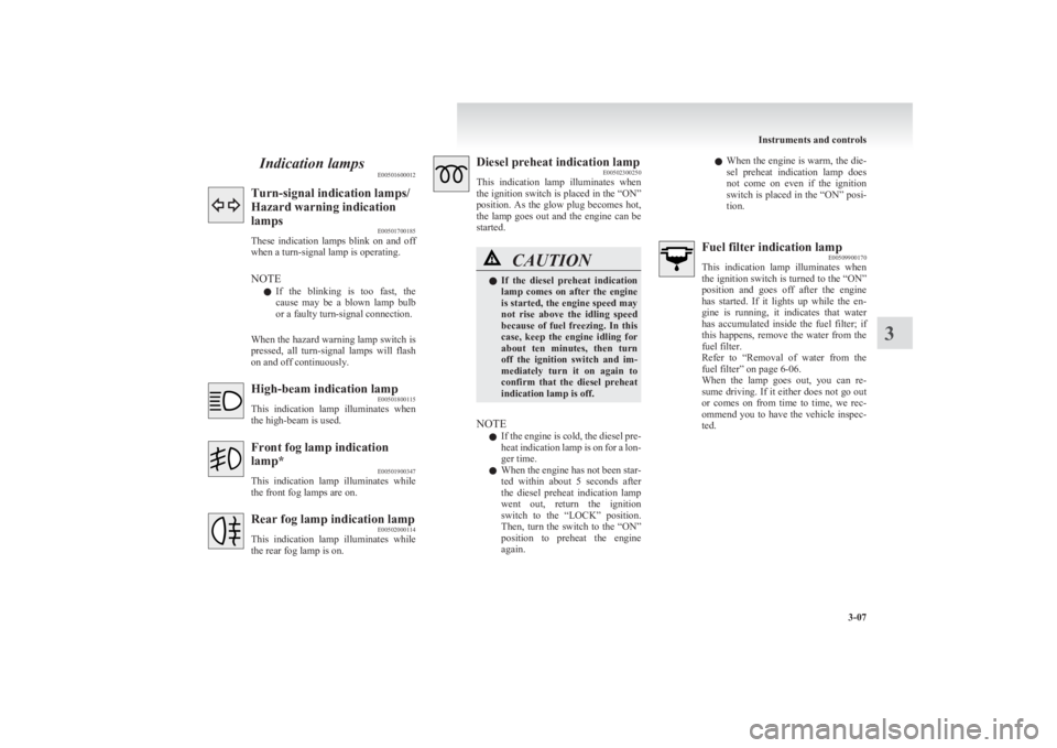
Indication lampsE00501600012Turn-signal indication lamps/
Hazard warning indication
lamps E00501700185
These indication lamps blink on and off
when a turn-signal lamp is operating.
NOTE l If the blinking is too fast, the
cause may be a blown lamp bulb
or a faulty turn-signal connection.
When the hazard warning lamp switch is
pressed, all turn-signal lamps will flash
on and off continuously.High-beam indication lamp E00501800115
This indication lamp illuminates when
the high-beam is used.Front fog lamp indication
lamp* E00501900347
This indication lamp illuminates while
the front fog lamps are on.Rear fog lamp indication lamp E00502000114
This indication lamp illuminates while
the rear fog lamp is on.Diesel preheat indication lamp E00502300250
This indication lamp illuminates when
the ignition switch is placed in the “ON”
position. As the glow plug becomes hot,
the lamp goes out and the engine can be
started.CAUTIONl If the diesel preheat indication
lamp comes on after the engine
is started, the engine speed may
not rise above the idling speed
because of fuel freezing. In this
case, keep the engine idling for
about ten minutes, then turn
off the ignition switch and im-
mediately turn it on again to
confirm that the diesel preheat
indication lamp is off.
NOTE
l If the engine is cold, the diesel pre-
heat indication lamp is on for a lon-
ger time.
l When the engine has not been star-
ted within about 5 seconds after
the diesel preheat indication lamp
went out, return the ignition
switch to the “LOCK” position.
Then, turn the switch to the “ON”
position to preheat the engine
again.
l When the engine is warm, the die-
sel preheat indication lamp does
not come on even if the ignition
switch is placed in the “ON” posi-
tion.Fuel filter indication lamp E00509900170
This indication lamp illuminates when
the ignition switch is turned to the “ON”
position and goes off after the engine
has started. If it lights up while the en-
gine is running, it indicates that water
has accumulated inside the fuel filter; if
this happens, remove the water from the
fuel filter.
Refer to “Removal of water from the
fuel filter” on page 6-06.
When the lamp goes out, you can re-
sume driving. If it either does not go out
or comes on from time to time, we rec-
ommend you to have the vehicle inspec-
ted.
Instruments and controls
3-07
3
Page 119 of 330
Switch position 0-Driver onlySwitch position 2-Driver + Full luggage load-
ing
{ Vehicles for Russia, Ka-
zakhstan and Ukraine with
heavy duty suspension}Switch position 3-Driver + Full luggage load-
ing
{ Vehicles for Russia, Ka-
zakhstan and Ukraine with-
out heavy duty suspension}
{ Except for vehicles for
Russia, Kazakhstan and Uk-
raine with heavy duty sus-
pension}Switch position 4-Driver + Full luggage load-
ing
{ Except for vehicles for
Russia, Kazakhstan and Uk-
raine without heavy duty
suspension}
Double cab
Vehicle condi- tionSwitch position“0”“2” or “3” or“4”●:1 person:Full luggage loadingSwitch position 0-Driver onlySwitch position 2-Driver + Full luggage load-
ing
{ Vehicles for Russia, Ka-
zakhstan and Ukraine with
heavy duty suspension}Switch position 3-Driver + Full luggage load-
ing
{ Vehicles for Russia, Ka-
zakhstan and Ukraine with-
out heavy duty suspension}
{ Except for vehicles for
Russia, Kazakhstan and Uk-
raine with heavy duty sus-
pension}Switch position 4-Driver + Full luggage load-
ing
{ Except for vehicles for
Russia, Kazakhstan and Uk-
raine without heavy duty
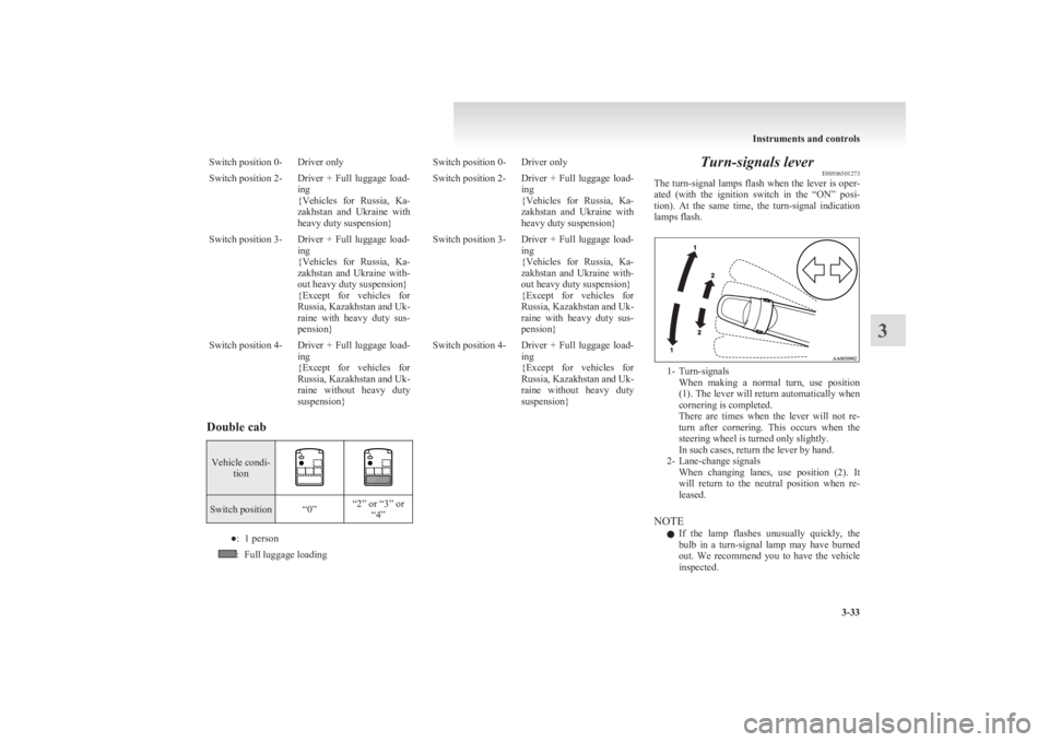
suspension}Turn-signals lever E00506501273
The turn-signal lamps flash when the lever is oper-
ated (with the ignition switch in the “ON” posi-
tion). At the same time, the turn-signal indication
lamps flash.
1- Turn-signals When making a normal turn, use position
(1). The lever will return automatically when
cornering is completed.
There are times when the lever will not re-
turn after cornering. This occurs when the
steering wheel is turned only slightly.
In such cases, return the lever by hand.
2- Lane-change signals When changing lanes, use position (2). It
will return to the neutral position when re-
leased.
NOTE l If the lamp flashes unusually quickly, the
bulb in a turn-signal lamp may have burned
out. We recommend you to have the vehicle
inspected.
Instruments and controls
3-33
3
Page 120 of 330
lIt is possible to activate the following func-
tions. For further information, we recom-
mend you to consult a MITSUBISHI
MOTORS Authorized Service Point. •Flashing of the turn-signal lamps and the
indication lamp in the instrument cluster
when the lever is operated with the igni-
tion switch in the “ACC” position
• Flashing of the turn-signal lamps and the
indication lamp in the instrument cluster
three times when you move the lever to
(2) slightly then release it
• The time required to operate the lever for
the 3-flash function can be adjusted.Hazard warning flasher switch E00506600903
Use the hazard warning flasher switch when the ve-
hicle has to be parked on the road for any emergency.
The hazard warning flashers can always be operat-
ed, regardless of the position of the ignition key.
Push the switch to turn on the hazard warning flash-
ers; push the switch again to turn them off.
When this switch is operated, all turn-signal lamps
flash continuously, as do the turn-signal indication
lamps in the instrument cluster.
NOTE
l If the lamps are kept flashing for a long time,
the battery will be discharged, resulting in
hard engine starting or no start condition.
l If the lamp flashes unusually quickly, the
bulb in a turn-signal lamp may have burned
out.
We recommend you to have the vehicle in-
spected.
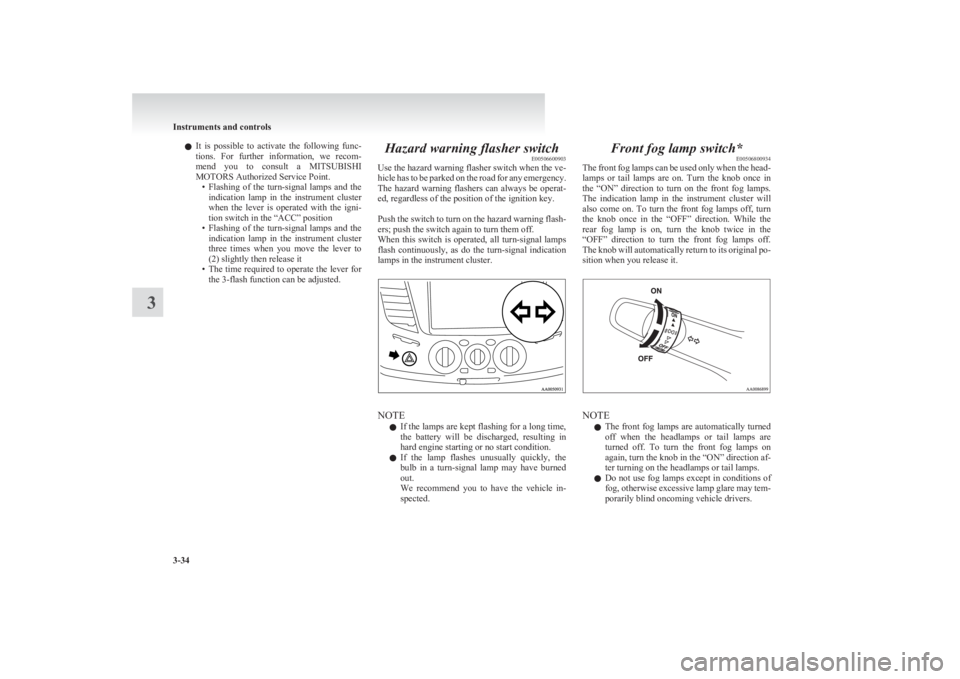
Front fog lamp switch* E00506800934
The front fog lamps can be used only when the head-
lamps or tail lamps are on. Turn the knob once in
the “ON” direction to turn on the front fog lamps.
The indication lamp in the instrument cluster will
also come on. To turn the front fog lamps off, turn
the knob once in the “OFF” direction. While the
rear fog lamp is on, turn the knob twice in the
“OFF” direction to turn the front fog lamps off.
The knob will automatically return to its original po-
sition when you release it.
NOTE
l The front fog lamps are automatically turned
off when the headlamps or tail lamps are
turned off. To turn the front fog lamps on
again, turn the knob in the “ON” direction af-
ter turning on the headlamps or tail lamps.
l Do not use fog lamps except in conditions of
fog, otherwise excessive lamp glare may tem-
porarily blind oncoming vehicle drivers.
Instruments and controls
3-34
3
Page 286 of 330
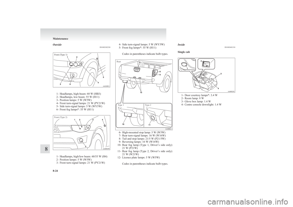
OutsideE01003302530Front (Type 1)
1- Headlamps, high-beam: 60 W (HB3)
2- Headlamps, low beam: 55 W (H11)
3- Position lamps: 5 W (W5W)
4- Front turn-signal lamps: 21 W (PY21W)
5- Side turn-signal lamps: 5 W (WY5W)
6- Front fog lamps*: 55 W (H11)
Front (Type 2)
1- Headlamps, high/low beam: 60/55 W (H4)
2- Position lamps: 5 W (W5W)
3- Front turn-signal lamps: 21 W (PY21W)
4- Side turn-signal lamps: 5 W (WY5W)
5- Front fog lamps*: 55 W (H11)
Codes in parentheses indicate bulb types.RearType 1Type 2
6- High-mounted stop lamp: 5 W (W5W)
7- Rear turn-signal lamps: 16 W (W16W)
8- Tail and stop lamps: 21/5 W (P21/5W)
9- Reversing lamps: 16 W (W16W)
10- Rear fog lamp (Type 1, Driver’s side only):
21 W (P21W)
11- Rear fog lamp (Type 2, Driver’s side only):
21 W (W21W)
12- Licence plate lamps: 5 W (W5W)
Codes in parentheses indicate bulb types.
Inside E01003401518
Single cab
1- Door courtesy lamps*: 3.4 W
2- Room lamp: 8 W
3- Glove box lamp: 1.4 W
4- Centre console downlight: 1.4 W
Maintenance
8-24
8
Page 289 of 330
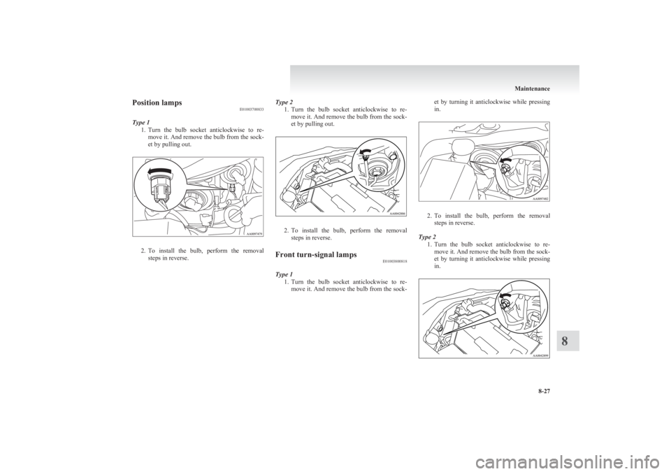
Position lampsE01003700833
Type 1 1.Turn the bulb socket anticlockwise to re-
move it. And remove the bulb from the sock-
et by pulling out.
2. To install the bulb, perform the removal
steps in reverse.
Type 2
1.Turn the bulb socket anticlockwise to re-
move it. And remove the bulb from the sock-
et by pulling out.
2. To install the bulb, perform the removal
steps in reverse.
Front turn-signal lamps E01003800818
Type 1
1.Turn the bulb socket anticlockwise to re-
move it. And remove the bulb from the sock-
et by turning it anticlockwise while pressing
in.
2. To install the bulb, perform the removal
steps in reverse.
Type 2 1.Turn the bulb socket anticlockwise to re-
move it. And remove the bulb from the sock-
et by turning it anticlockwise while pressing
in.
Maintenance
8-27
8
Page 290 of 330
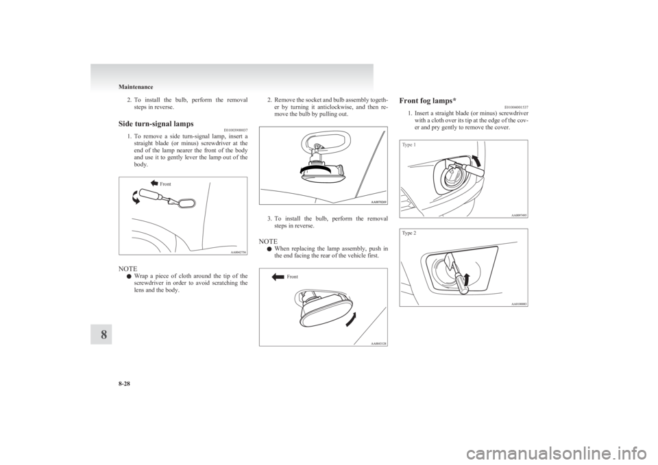
2.To install the bulb, perform the removal
steps in reverse.Side turn-signal lamps E01003900037
1.To remove a side turn-signal lamp, insert a
straight blade (or minus) screwdriver at the
end of the lamp nearer the front of the body
and use it to gently lever the lamp out of the
body.
Front
NOTE
l Wrap a piece of cloth around the tip of the
screwdriver in order to avoid scratching the
lens and the body.
2. Remove the socket and bulb assembly togeth-
er by turning it anticlockwise, and then re-
move the bulb by pulling out.
3. To install the bulb, perform the removal
steps in reverse.
NOTE l When replacing the lamp assembly, push in
the end facing the rear of the vehicle first.
FrontFront fog lamps* E01004001537
1. Insert a straight blade (or minus) screwdriver
with a cloth over its tip at the edge of the cov-
er and pry gently to remove the cover.Type 1Type 2
Maintenance
8-28
8
Page 292 of 330
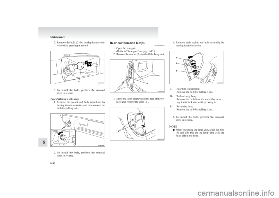
2.Remove the bulb (C) by turning it anticlock-
wise while pressing it inward.
3. To install the bulb, perform the removal
steps in reverse.
Type 2 (Driver’s side only) 1.Remove the socket and bulb assemblies by
turning it anticlockwise, and then remove the
bulb by pulling out.
2. To install the bulb, perform the removal
steps in reverse.
Rear combination lamps E01004200763
1. Open the rear gate.
(Refer to “Rear gate” on page 1-13.)
2. Remove the screws (A) that hold the lamp unit.
3.Move the lamp unit towards the rear of the ve-
hicle and remove the clips (B).
4. Remove each socket and bulb assembly by
turning it anticlockwise.C-Rear turn-signal lamp
Remove the bulb by pulling it out.D-Tail and stop lamp
Remove the bulb from the socket by turn-
ing it anticlockwise while pressing in.E-Reversing lamp
Remove the bulb by pulling it out.
5. To install the bulb, perform the removal
steps in reverse.
NOTE l When mounting the lamp unit, align the pins
(F) and clip (G) on the lamp unit with the
holes (H) in the body.
Maintenance
8-30
8
Page 322 of 330
Economical driving 4-02
Electric window control 1-08 Switch 1-08
Electrical system 9-16
Electronic immobilizer (Anti-theft starting sys-
tem) 1-03
Emergency starting 6-02
Engine specifications 9-14
Engine Coolant 8-05,9-21
Number 9-02
Oil 8-04,9-21
Overheating 6-04
Specifications 9-14
Used engine oils safety instructions and disposal
information 05
Water temperature gauge 3-05
Error codes 5-30
Exterior and interior lamp operation 8-18
F
First-aid kit and warning triangle band for secur-
ing 5-46
Floor console box 5-42
Fluid Automatic transmission fluid 8-06,9-21
Brake fluid 8-07,9-21
Clutch fluid 8-08,9-21
Engine coolant 8-05,9-21
Power steering fluid 8-09,9-21
Washer fluid 8-07,9-21
For cold and snowy weather 8-19
Front console box 5-42
Front fog lamps Bulb capacity 8-24
Indication lamp 3-07
Replacement 8-28
Switch 3-34
Front room lamp Bulb capacity 8-25
Replacement 8-32
Front seat 2-03
Front turn-signal lamps Bulb capacity 8-24
Replacement 8-27
Fuel consumption 9-19
Fuel Filling the fuel tank 02
Fuel filter indication lamp 3-07
Fuel gauge 3-04
Fuel selection 02
Low fuel warning lamp 3-04
Modification/alterations to the electrical or fuel
systems 04
Tank capacity 02
Fuses 8-20
Fusible links 8-19
G
Gauges 3-02
General maintenance 8-18
General vehicle data 9-03
Genuine parts 05
Glove box 5-42
Glove box lamp Bulb capacity 8-24
Replacement 8-33
H
Handling of compact discs 5-32
Hazard warning flasher switch 3-34
Hazard warning indication lamps 3-07
Head restraints 2-08
Headlamp levelling switch 3-32
Headlamps
Bulb capacity 8-24
Headlamp flasher 3-31
Replacement 8-25
Switch 3-30
Washer switch 3-39
Heated mirror 4-11
Heated seats 2-06
Heater 5-03
High-mounted stop lamp Bulb capacity 8-24
Replacement 8-31
Hinges and latches lubrication 8-19
Hooks Coat hook 5-46
Convenient hook 5-46
Horn switch 3-40
I
If the vehicle breaks down 6-02
Ignition switch 4-11
Indication and warning lamps 3-06
Indication lamps 3-07
Inside rear-view mirror 4-09
Inspection and maintenance following rough road
operation 4-40
Installation of accessories 04
Instruments 3-02
Interior lamps 5-39
J
Jack handle 6-12Storage 6-07
Jacking up the vehicle 6-13
Jack Storage 6-07
Jump starting (Emergency starting) 6-02
Alphabetical index
2
Page 323 of 330
K
Keyless entry system 1-04
Keys 1-02
L
Labeling 9-02
Lamp monitor buzzer 3-31
Lamps (headlamps, fog lamp, etc.) auto-cutout func-
tion 3-31
Leakage (Fuel, engine coolant, oil and exhaust
gas) 8-18
Licence plate lamps
Bulb capacity 8-24
Replacement 8-31
Limited-slip differential (LSD) 4-42
Low fuel warning lamp 3-04
Lubricants 9-21
LW/MW/FM electronic tuning radio with CD play-
er 5-13
M
Manual transmission 4-14Oil 9-21
Manual window control 1-08
Mirror Inside rear-view mirror 4-09
Outside rear-view mirrors 4-10
Vanity mirror 5-36
Modification/alterations to the electrical or fuel sys-
tems 04
O
Odometer 3-03
Oil
Differential oil 9-21
Engine oil 8-04,9-21
Manual transmission fluid 9-21
Transfer oil 9-21
Operation under adverse driving conditions 6-24
Other specifications 9-18
Outside rear-view mirrors 4-10
Overheating 6-04
P
Parking 4-08Parking brake 4-07
Parking brake lever stroke 8-16
Personal lamps 5-40 Replacement 8-32
Position lamps Bulb capacity 8-24
Replacement 8-27
Power steering Fluid 8-09,9-21
System 4-45
Precautions to observe when using wipers and wash-
ers 3-39
Pregnant women restraint 2-11
Puncture (Tyre changing) 6-17
R
RadioLW/MW/FM electronic tuning radio with CD
player 5-13
Rear combination lamps Bulb capacity 8-24
Replacement 8-30
Rear differential lock 4-34
Rear fog lamp Bulb capacity 8-24
Indication lamp 3-07
Replacement 8-29
Switch 3-35
Rear room lamp 5-39 Bulb capacity 8-25
Replacement 8-32
Rear seat 2-07
Rear side/quarter window 1-12
Rear turn-signal lamps Bulb capacity 8-24
Replacement 8-30
Rear window demister switch 3-40
Rear-view mirror Inside 4-09
Outside 4-10
Refill capacities 9-21
Removal of water from the fuel filter 6-06
Replacement of lamp bulbs 8-23
Reversing lamps Bulb capacity 8-24
Replacement 8-30
Room lamp 5-39,5-40
Running-in recommendations 4-04
S
Safe driving techniques 4-03
Seat belt 2-09 Adjustable seat belt anchor 2-11
Child restraint 2-13
Inspection 2-27
Pregnant women restraint 2-11
Pretensioner 2-12
Seat belt reminder/warning lamp 2-10
Seat under tray 5-44
Seat Adjustment 2-03
Armrest (Double cab) 2-07
Front seat 2-03
Head restraints 2-08
Alphabetical index
3
Page 324 of 330
Heated seats 2-06
Rear seat 2-07
Secret box 5-43
Service precaution 8-02
Side airbag system 2-35
Side turn-signal lamps Bulb capacity 8-24
Replacement 8-28
Snow tyres 8-14
Spare wheel 6-16
Spark plug 9-16
Specifications 9-02
Speedometer 3-03
Starting 4-13
Steering Power steering fluid 8-09,9-21
Power steering system 4-45
Steering wheel height adjustment 4-09
Steering wheel lock 4-12
Steering wheel remote control switch 5-28
Stop lamps Bulb capacity 8-23
Replacement 8-30
Storage spaces 5-41
Sun visors 5-35
Sunglasses holder 5-43
Sunroof 1-13 Safety mechanism 1-14
Sunshade 1-14
Switch 1-13
Super select 4WD 4-29
Supplemental restraint system 2-27 How the Supplemental Restraint System
works 2-29
Servicing 2-39
Warning lamp 2-38
T
Tachometer 3-03
Tail lamps Bulb capacity 8-24
Replacement 8-30
Tank capacity 02
Ticket holder 5-35
Tools 6-09 Storage 6-07
Towing 6-20
Trailer towing 4-53
Transfer oil 9-21
Transmission Automatic transmission 4A/T 4-16
Automatic transmission Sports Mode 5A/
T 4-20
Fluid 8-06,9-21
Manual transmission 4-14
Specifications 9-15
Tripmeter 3-03
Turn-signal indication lamps 3-07
Turn-signals lever 3-33
Tyres 8-11 How to change a tyre 6-17
Inflation pressures 8-12
Rotation 8-13
Size (tyre and wheel) 9-17
Snow tyres 8-14
Tyre chains 8-14
Wheel condition 8-13
U
Used engine oils safety instructions and disposal in-
formation 05
Utility box 5-43
V
Vanity mirror 5-36
Vehicle care precautions 7-02
Vehicle dimensions 9-03
Vehicle identification number 9-02
Vehicle identification number plate 9-02
Vehicle information code plate 9-02
Vehicle labeling 9-02
Vehicle performance 9-09
Vehicle weight 9-10
Ventilators 5-02
W
Warning lamps 3-08
Washer Fluid 8-07,9-21
Switch 3-36,3-39
Washing 7-03
Water temperature gauge 3-05
Waxing 7-04
Weatherstripping 8-19
Weight 9-10
Wheel condition 8-13
Wheel Specification 9-17
Wiper Switch 3-36
Wiper blade rubber replacement 8-17
Wiper blades 8-17
Alphabetical index
4