fuel type MITSUBISHI L200 2012 Owner's Manual (in English)
[x] Cancel search | Manufacturer: MITSUBISHI, Model Year: 2012, Model line: L200, Model: MITSUBISHI L200 2012Pages: 370, PDF Size: 23.14 MB
Page 4 of 370
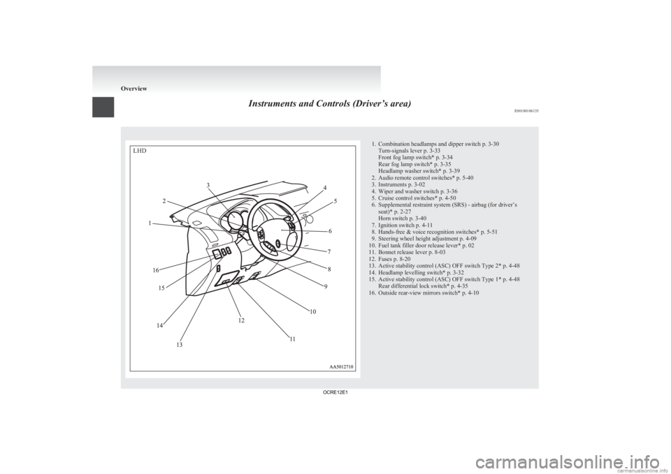
Instruments and Controls (Driver’s area)
E00100106135 1. Combination headlamps and dipper switch p. 3-30
Turn-signals lever p. 3-33
Front fog lamp switch* p. 3-34
Rear fog lamp switch* p. 3-35
Headlamp washer switch* p. 3-39
2.
Audio remote control switches* p. 5-40
3. Instruments p. 3-02
4. Wiper and washer switch p. 3-36
5. Cruise control switches* p. 4-50
6. Supplemental restraint system (SRS) - airbag (for driver’s seat)* p. 2-27
Horn switch p. 3-40
7. Ignition switch p. 4-11
8. Hands-free & voice recognition switches* p. 5-51
9. Steering wheel height adjustment p. 4-09
10. Fuel tank filler door release lever* p. 02
11. Bonnet release lever p. 8-03
12. Fuses p. 8-20
13. Active stability control (ASC) OFF switch Type 2* p. 4-48
14. Headlamp levelling switch* p. 3-32
15. Active stability control (ASC) OFF switch Type 1* p. 4-48 Rear differential lock switch* p. 4-35
16. Outside rear-view mirrors switch* p. 4-10 OverviewLHD
OCRE12E1
Page 5 of 370
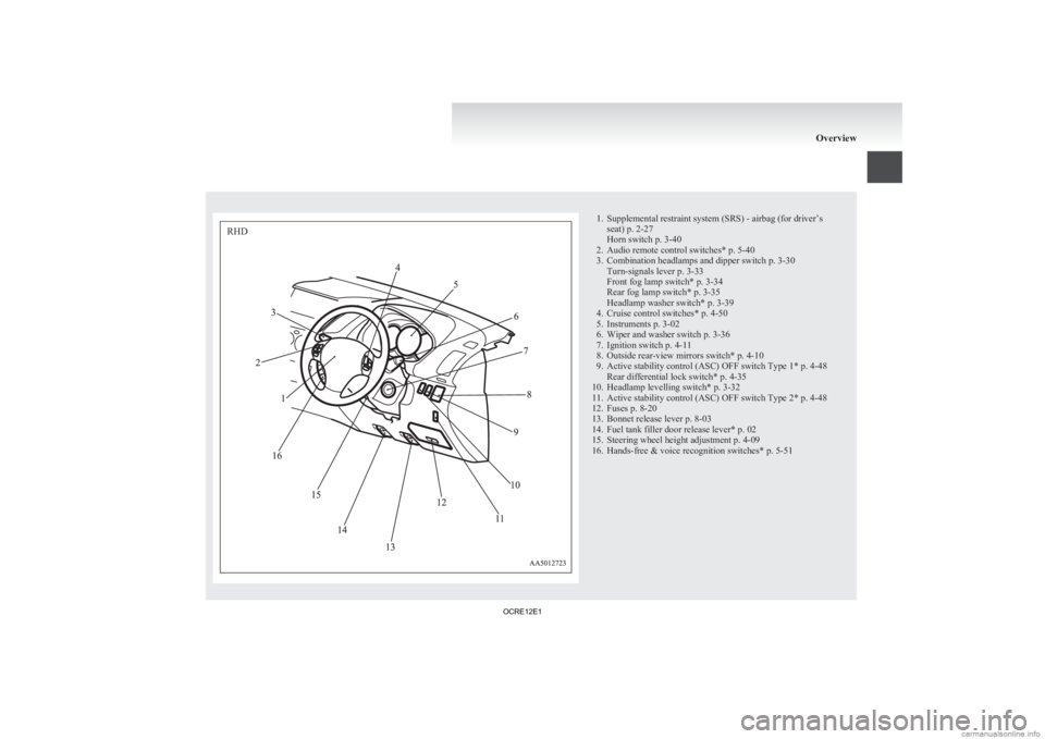
1. Supplemental restraint system (SRS) - airbag (for driver’s
seat) p. 2-27
Horn switch p. 3-40
2.
Audio remote control switches* p. 5-40
3. Combination headlamps and dipper switch p. 3-30 Turn-signals lever p. 3-33
Front fog lamp switch* p. 3-34
Rear fog lamp switch* p. 3-35
Headlamp washer switch* p. 3-39
4. Cruise control switches* p. 4-50
5. Instruments p. 3-02
6. Wiper and washer switch p. 3-36
7. Ignition switch p. 4-11
8. Outside rear-view mirrors switch* p. 4-10
9. Active stability control (ASC) OFF switch Type 1* p. 4-48 Rear differential lock switch* p. 4-35
10. Headlamp levelling switch* p. 3-32
11. Active stability control (ASC) OFF switch Type 2* p. 4-48
12. Fuses p. 8-20
13. Bonnet release lever p. 8-03
14. Fuel tank filler door release lever* p. 02
15. Steering wheel height adjustment p. 4-09
16. Hands-free & voice recognition switches* p. 5-51 OverviewRHD
OCRE12E1
Page 26 of 370
Fuel selection
E00200102141Recommended fuel
Cetane number (EN590)
51 or higher CAUTION
l
Your vehicle is designed to use only diesel
fuel that meets the EN 590 standard.
Use of any other type of diesel fuel would
adversely affect the engine’s performance
and durability.
NOTE l Due
to the separation of paraffin, the fluidity
of the fuel decreases considerably as the tem-
perature falls.
Because of this fact there are two kinds of
fuel: “summer” and “winter”.
This must be considered in winter use.
Select either of the two kinds of fuel in ac-
cordance with ambient temperature. Above -5 °C: “Summer” diesel
Below -5 °C: “Winter” diesel
When travelling abroad, find out in advance
about the fuels served in local service stations. l
Poor-quality
diesel fuel can cause deposits to
form in the injector, resulting in black smoke
and rough idling.
If these problems occur, you are advised to
add a cleaning additive to the diesel fuel
when you refuel the vehicle.
The additive will break up and remove the de-
posits, thereby returning the engine to a nor-
mal condition.
Be sure to use a genuine MITSUBISHI DIE-
SEL FUEL SYSTEM CLEANER. Using an
unsuitable additive could make the engine
malfunction. For details, please contact your
MITSUBISHI MOTORS Authorized Service
Point. Filling the fuel tank
E00200202025 WARNING
l When
handling fuel, comply with the safe-
ty regulations displayed by garages and
filling stations.
l Before removing the fuel cap, be sure to
get rid of your body’s static electricity by
touching a metal part of the car or the
fuel pump. Any static electricity on your
body could create a spark that ignites
fuel vapour.
l Perform the whole refueling process
(opening the fuel tank filler door, remov-
ing the fuel cap, etc.) by yourself. Do not
let any other person come near the fuel
tank filler. If you allowed a person to
help you and that person was carrying
static electricity, fuel vapour could be ig-
nited.
l Do not move away from the fuel tank fill-
er until refueling is finished. If you
moved away and did something else (for
example, cleaning your windscreen) part-
way through the refueling process, you
could pick up a fresh charge of static elec-
tricity.
l If the tank cap must be replaced, use only
a MITSUBISHI MOTORS original part.
Fuel tank capacity
75 litres
Refueling 1.
Before filling with fuel, stop the engine. General information
02
OCRE12E1
Page 27 of 370
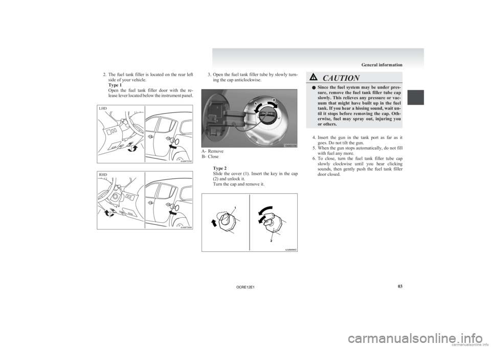
2. The fuel tank filler is located on the rear left
side of your vehicle.
Type 1
Open the fuel tank filler door with the re-
lease lever located below the instrument panel. 3. Open the fuel tank filler tube by slowly turn-
ing the cap anticlockwise. A- Remove
B-
Close
Type 2
Slide the cover (1). Insert the key in the cap
(2) and unlock it.
Turn the cap and remove it. CAUTION
l
Since
the fuel system may be under pres-
sure, remove the fuel tank filler tube cap
slowly. This relieves any pressure or vac-
uum that might have built up in the fuel
tank. If you hear a hissing sound, wait un-
til it stops before removing the cap. Oth-
erwise, fuel may spray out, injuring you
or others.
4. Insert
the gun in the tank port as far as it goes. Do not tilt the gun.
5. When the gun stops automatically, do not fill with fuel any more.
6. To close, turn the fuel tank filler tube cap slowly clockwise until you hear clicking
sounds, then gently push the fuel tank filler
door closed. General information
03LHD RHD
OCRE12E1
Page 88 of 370
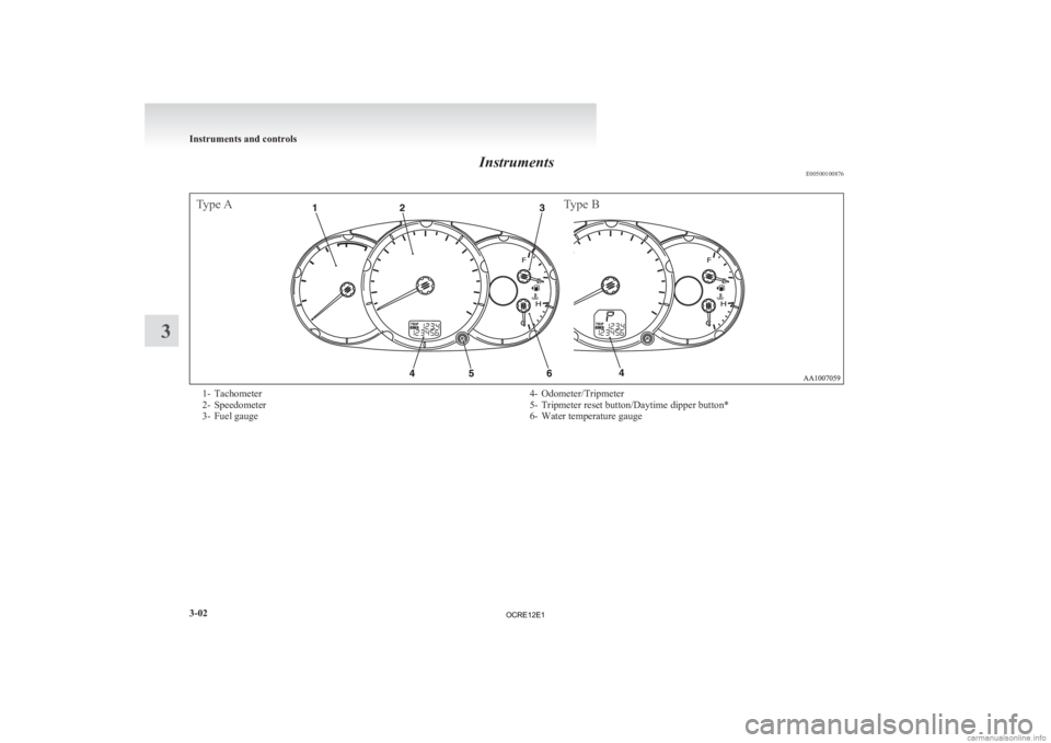
Instruments
E00500100876Type AType B1- Tachometer
2-
Speedometer
3- Fuel gauge 4- Odometer/Tripmeter
5-
Tripmeter reset button/Daytime dipper button*
6- Water temperature gauge Instruments and controls
3-02
3
OCRE12E1
Page 90 of 370
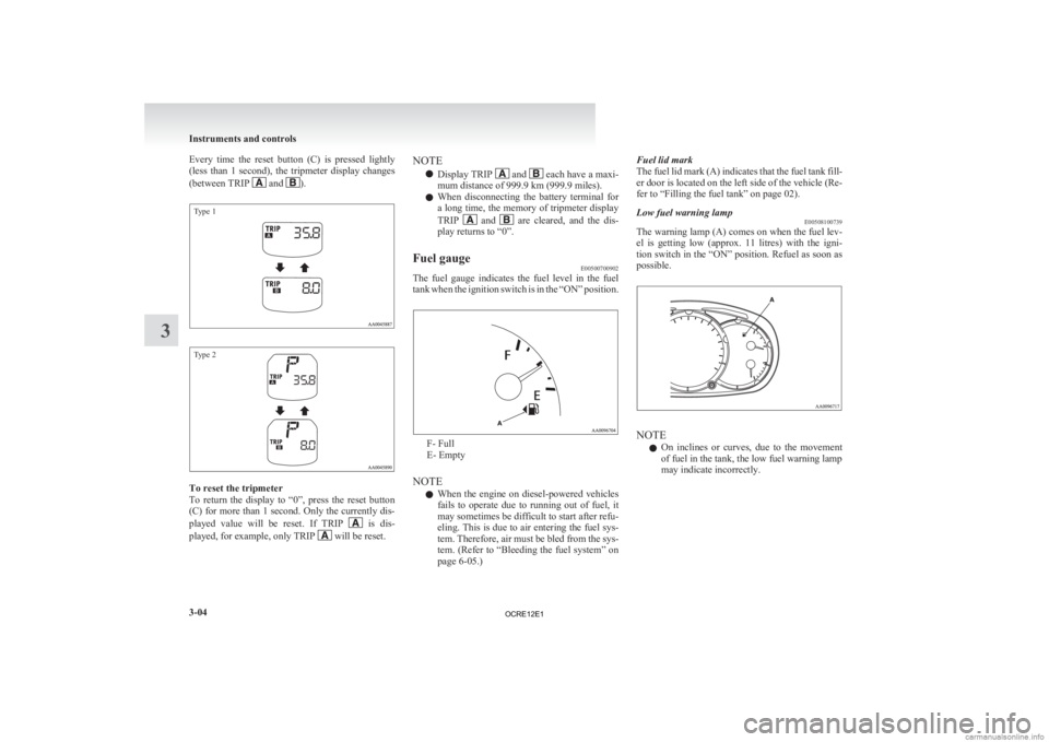
Every time the reset button (C) is pressed lightly
(less
than 1 second), the tripmeter display changes
(between TRIP and ).
Type 1
Type 2
To reset the tripmeter
To
return the display to “0”, press the reset button
(C) for more than 1 second. Only the currently dis-
played value will be reset. If TRIP is dis-
played, for example, only TRIP will be reset.NOTE
l Display TRIP and each have a maxi-
mum distance of 999.9 km
(999.9 miles).
l When disconnecting the battery terminal for
a long time, the memory of tripmeter display
TRIP and are cleared, and the dis-
play returns to “0”.
Fuel gauge E00500700902
The fuel gauge indicates the fuel level in the fuel
tank
when the ignition switch is in the “ON” position. F- Full
E- Empty
NOTE l When
the engine on diesel-powered vehicles
fails to operate due to running out of fuel, it
may sometimes be difficult to start after refu-
eling. This is due to air entering the fuel sys-
tem. Therefore, air must be bled from the sys-
tem. (Refer to “Bleeding the fuel system” on
page 6-05.) Fuel lid mark
The
fuel lid mark (A) indicates that the fuel tank fill-
er door is located on the left side of the vehicle (Re-
fer to “Filling the fuel tank” on page 02).
Low fuel warning lamp E00508100739
The warning lamp (A) comes on when the fuel lev-
el
is getting low (approx. 11 litres) with the igni-
tion switch in the “ON” position. Refuel as soon as
possible. NOTE
l On
inclines or curves, due to the movement
of fuel in the tank, the low fuel warning lamp
may indicate incorrectly. Instruments and controls
3-04
3
OCRE12E1
Page 92 of 370
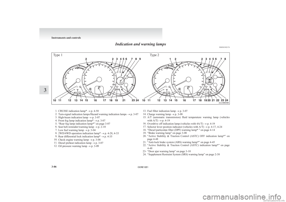
Indication and warning lamps
E00501502174Type 1Type 21.
CRUISE indication lamp*
® p. 4-50
2. Turn-signal indication lamps/Hazard warning indication lamps ® p. 3-07
3. High-beam indication lamp ® p. 3-07
4. Front fog lamp indication lamp* ® p. 3-07
5. “Rear fog lamp indication lamp*” on page 3-07
6. Seat belt reminder/warning lamp ® p. 2-10
7. Low fuel warning lamp ® p. 3-04
8. 2WD/4WD operation indication lamp* ® p. 4-28, 4-33
9. Rear differential lock indication lamp* ® p. 4-35
10. Check engine warning lamp ® p. 3-08
11. Diesel preheat indication lamp ® p. 3-07
12. Oil pressure warning lamp ® p. 3-09 13.
Fuel filter indication lamp ® p. 3-07
14. Charge warning lamp ® p. 3-09
15. A/T (automatic transmission) fluid temperature warning lamp (vehicles
with A/T) ® p. 4-19
16. Overdrive off indication lamp (vehicles with 4A/T) ® p. 4-19
17. Selector lever position indicator (vehicles with A/T) ® p. 4-17, 4-24
18. “Diesel particulate filter (DPF) warning lamp* ” on page 4-14
19. “Brake warning lamp” on page 3-08
20. “Active Stability & Traction Control (ASTC) OFF indication lamp*” on page 4-48
21. “Anti-lock brake system (ABS) warning lamp*” on page 4-45
22. “Active Stability & Traction Control (ASTC) indication lamp*” on page 4-48
23- “Door ajar warning lamp” on page 3-10 24. “Supplement Restraint System (SRS) warning lamp” on page 2-38 Instruments and controls
3-06
3
OCRE12E1
Page 140 of 370
l
When the engine has not been started within
about 5 seconds after the diesel preheat indi-
cation lamp went out, return the ignition key
to the “LOCK” position. Then, turn the key
to the “ON” position to preheat the engine
again.
l When the engine is warm, the diesel preheat
indication lamp does not come on even if the
ignition key is placed in the “ON” position.
Start the engine by turning the ignition key
right to the “START” position.
6. Operate the accelerator pedal as described be- low in accordance with the atmospheric tem-
perature and/or engine condition and then
start the engine.
l When the atmospheric temperature is
moderate or the engine is warm, start the
engine without depressing the accelerator
pedal.
l When the atmospheric temperature is low
and the engine is cold, start the engine
while depressing the accelerator pedal.
Fuel injection amount learning process E00616000028
To keep exhaust emissions and engine noise low,
the
engine very occasionally performs a learning
process for the fuel injection amount.
The engine sounds slightly different from usual
while the learning process is taking place. The
change in the engine sound does not indicate a fault. Diesel particulate filter (DPF)*
E00619800232
The
diesel particulate filter (DPF) is a device that
captures most of the particulate matter (PM) in the
exhaust emissions of the diesel engine. The DPF au-
tomatically burns away trapped PM during vehicle
operation. Under certain driving conditions, howev-
er, the DPF is not able to burn away all of the trap-
ped PM and, as a result, an excessive amount of
PM accumulates inside it. WARNING
l The DPF reaches very high temperatures.
Do
not park your vehicle in areas where
combustible materials such as dry grass
or leaves can come in contact with a hot
exhaust system since a fire could occur. CAUTION
l
Do
not use any type of fuel or engine oil
that is not specified for your vehicle. Al-
so, do not use any moisture-removing
agent or other fuel additive. Such substan-
ces could have a detrimental effect on the
DPF.
Refer to “Fuel selection” on page 02 and
“Engine oil” on page 8-04.
NOTE l To
minimize the likelihood of excessive ac-
cumulation of PM, try to avoid driving for
long periods at low speeds and repeatedly
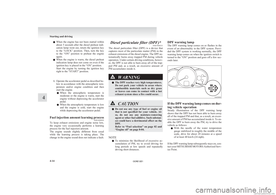
driving short distances. DPF warning lamp
The
DPF warning lamp comes on or flashes in the
event of an abnormality in the DPF system. Provi-
ded the DPF system is working normally, the DPF
warning lamp comes on when the ignition switch is
turned to the “ON” position and goes off a few sec-
onds later. If the DPF warning lamp comes on dur-
ing vehicle operation
Steady
illumination of the DPF warning lamp
shows that the DPF has not been able to burn away
all of the trapped PM and that, as a result, an exces-
sive amount of PM has accumulated inside it. To en-
able the DPF to burn away the PM, try to drive the
vehicle as follows:
l With the needle of the water temperature
gauge stabilized in roughly the middle of the
scale, drive for about 20 minutes at a speed
of at least 40 km/h (24 mph).
If the DPF warning lamp subsequently stays on, con-
tact your MITSUBISHI MOTORS Authorized Serv-
ice Point. Starting and driving
4-14
4
OCRE12E1
Page 271 of 370
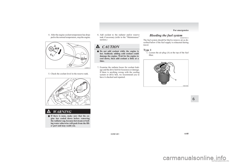
4. After the engine coolant temperature has drop-
ped to the normal temperature, stop the engine. 5. Check the coolant level in the reserve tank.
WARNING
l If
there is none, make sure that the en-
gine has cooled down before removing
the radiator cap, because hot steam or boil-
ing water otherwise will gush from the fill-
er port and may scald you. 6. Add
coolant to the radiator and/or reserve
tank if necessary (refer to the “Maintenance”
section.) CAUTION
l
Do
not add coolant while the engine is
hot. Suddenly adding cold coolant could
damage the engine. Wait for the engine to
cool down, then add coolant a little at a
time.
7. Examine
the radiator hoses for coolant leak- age and the drive belt for looseness or damage.
If there is anything wrong with the cooling
system or drive belt, we recommend you to
have it checked and repaired. Bleeding the fuel system
E00800700312
The fuel system should be bled to remove air as de-
scribed below if the fuel supply is exhausted during
travel.
Type 1
1. Loosen
the air plug (A) at the top of the fuel
filter. For emergencies
6-05 6
OCRE12E1
Page 272 of 370
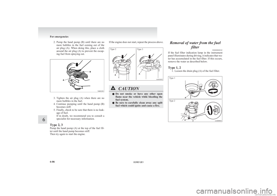
2. Pump the hand pump (B) until there are no
more bubbles in the fuel coming out of the
air plug (A). When doing this, place a cloth
around the air plug (A) to prevent the escap-
ing fuel from spraying out. 3. Tighten
the air plug (A) when there are no
more bubbles in the fuel.
4. Continue pumping until the hand pump (B) becomes stiff.
5. Finally, check to be sure that there is no leak- age of fuel.
If in doubt, we recommend you to consult a
specialist for necessary information.
Type 2, 3
Pump the hand pump (A) at the top of the fuel fil-
ter until the hand pump becomes stiff.
Then try again to start the engine. If the engine does not start, repeat the process above.
Type 2
Type 3 CAUTION
l
Do
not smoke or have any other open
flame near the vehicle while bleeding the
fuel system.
l Be sure to carefully clean away any spilt
fuel which could ignite and cause a fire. Removal of water from the fuel
filterE00800800342
If
the fuel filter indication lamp in the instrument
panel illuminates during driving, it indicates that wa-
ter has accumulated in the fuel filter. If this occurs,
remove the water as described below.
Type 1, 2
1. Loosen the drain plug (A) of the fuel filter.
Type 1
Type 2 For emergencies
6-06
6
OCRE12E1