maintenance MITSUBISHI L200 2013 (in English) Service Manual
[x] Cancel search | Manufacturer: MITSUBISHI, Model Year: 2013, Model line: L200, Model: MITSUBISHI L200 2013Pages: 362, PDF Size: 21.07 MB
Page 324 of 362

Front room lamp and personal lamps*E01004700364
1.Insert a straight blade (or minus) screwdriver
into the notch of the lens and pry gently to re-
move it.
Remove the bulb from the lamp holder.
NOTE
l Wrap a piece of cloth around the tip of the
screwdriver in order to avoid scratching the
lens.
2. To install the bulb, perform the removal
steps in reverse.
NOTE
l When installing the lens, align the 2 tabs on
the lens with the holes on the vehicle side.Rear room lamp* E01004900119
Type 1
1.Insert a straight blade (or minus) screwdriver
into the notch of the lens and pry gently to re-
move it. Remove the bulb from the lamp hold-
er.
NOTE
l Wrap a piece of cloth around the tip of the
screwdriver in order to avoid scratching the
lens.
2. To install the bulb, perform the removal
steps in reverse.
NOTE l When installing the lens, fit the two tabs on
one side of the lens into the holes on the vehi-
cle side before fitting the two tabs on the op-
posite side of the lens into the holes on the ve-
hicle side.
Type 2
1.Insert a straight blade (or minus) screwdriver
into the notch of the lens and pry gently to re-
move it. Remove the bulb from the lamp hold-
er.
Maintenance
8-32 OKTE13E1
8
Page 325 of 362

NOTEl Wrap a piece of cloth around the tip of the
screwdriver in order to avoid scratching the
lens.
2. To install the bulb, perform the removal
steps in reverse.
NOTE l When installing the lens, align the 2 tabs on
the lens with the holes on the vehicle side.
Door courtesy lamps* E01005400238
1. Insert a straight blade (or minus) screwdriver
into the lens and pry gently to remove it. Re-
move the bulb from the lamp holder.
NOTE
l Wrap a piece of cloth around the tip of the
screwdriver in order to avoid scratching the
lens.
2. To install the bulb, perform the removal
steps in reverse.
NOTE
l When installing the lens, align the 2 tabs on
the lens with the holes on the vehicle side.Glove box lamp E01006100069
We recommend you to have the glove box lamp re-
placed by a specialist.
Centre console downlight E01008700144Type 1Type 2
Maintenance
8-33
OKTE13E1
8
Page 326 of 362
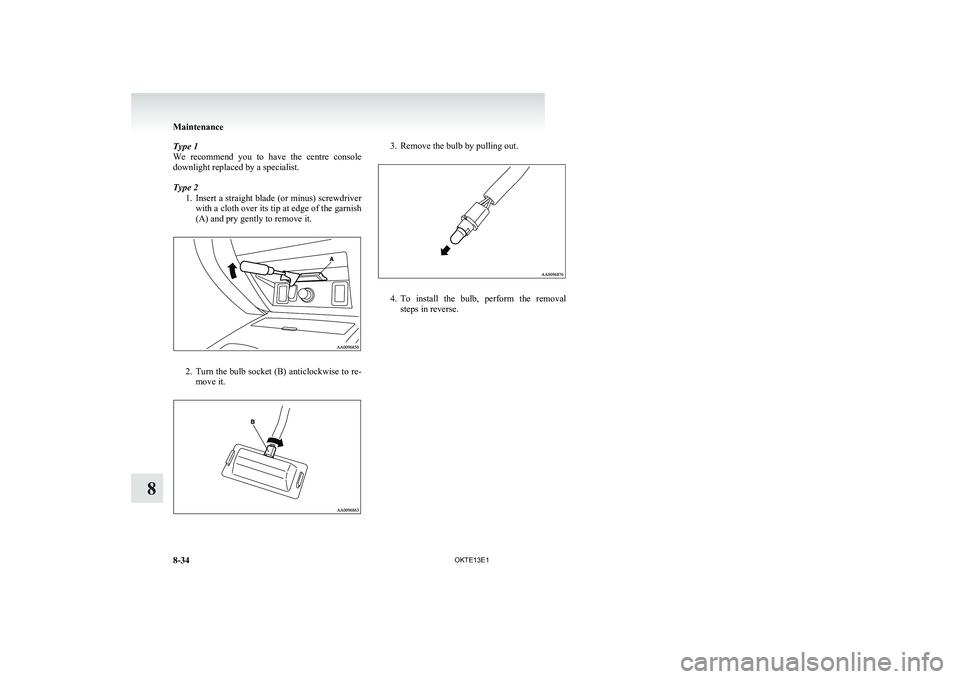
Type 1
We recommend you to have the centre console
downlight replaced by a specialist.
Type 2 1.Insert a straight blade (or minus) screwdriver
with a cloth over its tip at edge of the garnish
(A) and pry gently to remove it.
2. Turn the bulb socket (B) anticlockwise to re-
move it.
3. Remove the bulb by pulling out.
4. To install the bulb, perform the removal
steps in reverse.
Maintenance
8-34 OKTE13E1
8
Page 345 of 362

Fuel consumptionE01101100717
Item
CombinedUrban conditionsExtra-urban condi-
tionsCO2 (g/km)Fuel consumption
(L/100 km)Fuel consumption(L/100 km)Fuel consumption(L/100 km)Single cab2WD1907.29.16.14WDStandard1957.48.76.7Full option1997.58.96.8Club cabStandard1997.58.96.8Full option2047.79.17.0Double cab2WD with 15 inch tyresStandard1907.29.16.1Full option1947.49.26.32WD with 16 inch
tyresM/TStandard1957.48.76.7Full option2047.79.17.0A/TStandard2228.410.27.4Full option2278.610.57.64WDM/TStandard2047.79.17.0Full option2087.99.27.2A/TStandard2258.510.27.6Full option2338.810.67.9
NOTE
l The results given do not express or imply any guarantee of the fuel consumption of the particular vehicle.
The vehicle itself has not been tested and there are inevitably differences between individual vehicles of the same model. In addition, this vehicle may incor-
porate particular modifications. Furthermore, the driver’s style and road and traffic conditions, as well as the extent to which the vehicle has been driven and
the standard of maintenance, will all affect its fuel consumption.
Specifications
9-19
OKTE13E1
9
Page 350 of 362
Switch 1-08
Electrical system 9-16
Electronic immobilizer (Anti-theft starting sys-
tem) 1-03
Emergency starting 6-02
Engine specifications 9-14
Engine Coolant 8-06,9-20
Number 9-02
Oil 8-04,9-20
Overheating 6-04
Specifications 9-14
Used engine oils safety instructions and disposal
information 05
Water temperature gauge 3-05
Error codes 5-42
Exterior and interior lamp operation 8-18
F
First-aid kit and warning triangle band for secur-
ing 5-80
Floor console box 5-76
Fluid Automatic transmission fluid 8-07,9-20
Brake fluid 8-08,9-20
Clutch fluid 8-09,9-20
Engine coolant 8-06,9-20
Power steering fluid 8-09,9-20
Washer fluid 8-08,9-20
For cold and snowy weather 8-19
Front console box 5-76
Front fog lamps Bulb capacity 8-24
Indication lamp 3-07
Replacement 8-28
Switch 3-34
Front room lamp Bulb capacity 8-25
Replacement 8-32
Front seat 2-03
Front turn-signal lamps Bulb capacity 8-24
Replacement 8-27
Fuel consumption 9-19
Fuel Filling the fuel tank 02
Fuel filter indication lamp 3-07
Fuel gauge 3-04
Fuel selection 02
Low fuel warning lamp 3-04
Modification/alterations to the electrical or fuel
systems 04
Tank capacity 02
Fuses 8-20
Fusible links 8-19
G
Gauges 3-02
General maintenance 8-18
General vehicle data 9-03
Genuine parts 05
Glove box 5-76
Glove box lamp Bulb capacity 8-24
Replacement 8-33
H
Handling of compact discs 5-48
Hazard warning flasher switch 3-34
Hazard warning indication lamps 3-07
Head restraints 2-08
Headlamp levelling switch 3-32
Headlamps Bulb capacity 8-24
Headlamp flasher 3-31
Replacement 8-25
Switch 3-30
Washer switch 3-39
Heated mirror 4-10
Heated seats 2-06
Heater 5-03
High-mounted stop lamp Bulb capacity 8-24
Replacement 8-31
Hinges and latches lubrication 8-19
Hooks Coat hook 5-80
Convenient hook 5-80
Horn switch 3-40
I
If the vehicle breaks down 6-02
Ignition switch 4-10
Indication and warning lamps 3-06
Indication lamps 3-07
Inside rear-view mirror 4-08
Inspection and maintenance following rough road
operation 4-37
Installation of accessories 04
Instruments 3-02
Interior lamps 5-73
J
Jack handle 6-12Storage 6-07
Jacking up the vehicle 6-13
Jack Storage 6-07
Jump starting (Emergency starting) 6-02
Alphabetical index
2