glove box MITSUBISHI L200 2013 Owner's Manual (in English)
[x] Cancel search | Manufacturer: MITSUBISHI, Model Year: 2013, Model line: L200, Model: MITSUBISHI L200 2013Pages: 362, PDF Size: 21.07 MB
Page 6 of 362
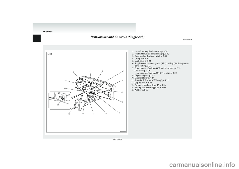
Instruments and Controls (Single cab)E001001061481. Hazard warning flasher switch p. 3-34
2. Heater/Manual air conditioning* p. 5-03
3. Rear window demister switch p. 3-40
4. Utility box p. 5-77
5. Ventilators p. 5-02
6. Supplemental restraint system (SRS) - airbag (for front passen- ger’s seat)* p. 2-27
7. Front passenger’s airbag OFF indication lamp p. 2-32
8. Glove box p. 5-76 Front passenger’s airbag ON-OFF switch p. 2-30
9. Cigarette lighter p. 5-71
10. Gearshift lever p. 4-14
11. Transfer shift lever (4WD only) p. 4-22
12. Cup holder* p. 5-78
13. Parking brake lever Type 1* p. 4-06
14. Parking brake lever Type 2* p. 4-06
15. Ashtray p. 5-70
Overview
OKTE13E112
3
4
5
6
78
9
10
11
12
13
14 15
LHD
Page 7 of 362
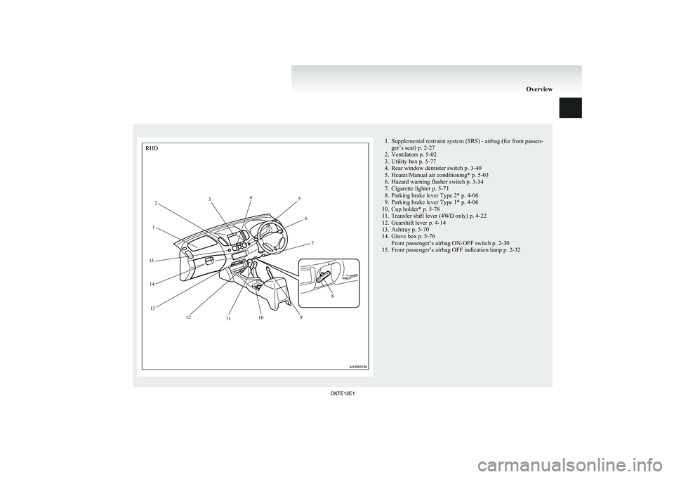
1. Supplemental restraint system (SRS) - airbag (for front passen-ger’s seat) p. 2-27
2. Ventilators p. 5-02
3. Utility box p. 5-77
4. Rear window demister switch p. 3-40
5. Heater/Manual air conditioning* p. 5-03
6. Hazard warning flasher switch p. 3-34
7. Cigarette lighter p. 5-71
8. Parking brake lever Type 2* p. 4-06
9. Parking brake lever Type 1* p. 4-06
10. Cup holder* p. 5-78
11. Transfer shift lever (4WD only) p. 4-22
12. Gearshift lever p. 4-14
13. Ashtray p. 5-70
14. Glove box p. 5-76 Front passenger’s airbag ON-OFF switch p. 2-30
15. Front passenger’s airbag OFF indication lamp p. 2-32
Overview
OKTE13E112
3
4
5
6
7
8
9
10
11
12
13
14
15
RHD
Page 8 of 362
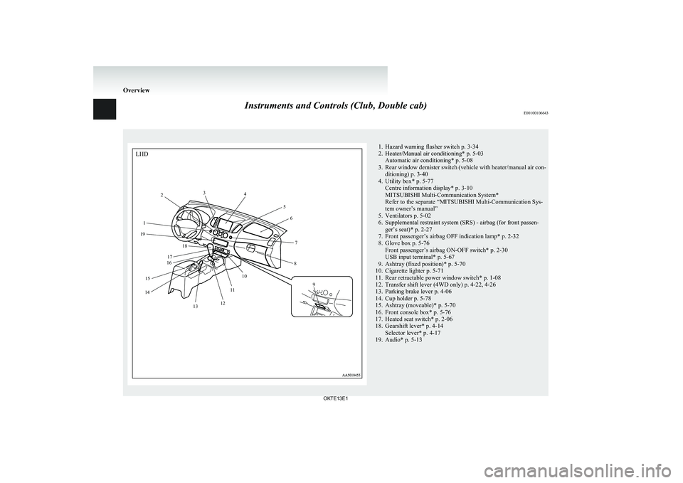
Instruments and Controls (Club, Double cab)E001001066431. Hazard warning flasher switch p. 3-34
2. Heater/Manual air conditioning* p. 5-03 Automatic air conditioning* p. 5-08
3. Rear window demister switch (vehicle with heater/manual air con-
ditioning) p. 3-40
4. Utility box* p. 5-77 Centre information display* p. 3-10
MITSUBISHI Multi-Communication System*
Refer to the separate “MITSUBISHI Multi-Communication Sys-
tem owner’s manual”
5. Ventilators p. 5-02
6. Supplemental restraint system (SRS) - airbag (for front passen- ger’s seat)* p. 2-27
7. Front passenger’s airbag OFF indication lamp* p. 2-32
8. Glove box p. 5-76 Front passenger’s airbag ON-OFF switch* p. 2-30
USB input terminal* p. 5-67
9. Ashtray (fixed position)* p. 5-70
10. Cigarette lighter p. 5-71
11. Rear retractable power window switch* p. 1-08
12. Transfer shift lever (4WD only) p. 4-22, 4-26
13. Parking brake lever p. 4-06
14. Cup holder p. 5-78
15. Ashtray (moveable)* p. 5-70
16. Front console box* p. 5-76
17. Heated seat switch* p. 2-06
18. Gearshift lever* p. 4-14 Selector lever* p. 4-17
19. Audio* p. 5-13
Overview
OKTE13E1LHD1 2
3
4
56
7
8
9
10
11
12
13
14 15 16
17 18
19
Page 9 of 362
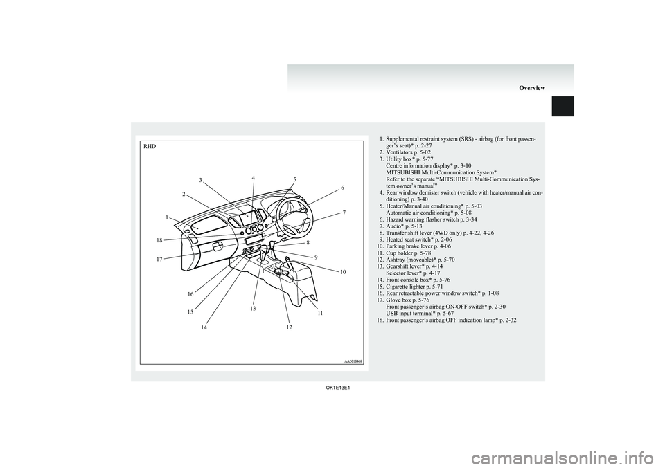
1. Supplemental restraint system (SRS) - airbag (for front passen-ger’s seat)* p. 2-27
2. Ventilators p. 5-02
3. Utility box* p. 5-77 Centre information display* p. 3-10
MITSUBISHI Multi-Communication System*
Refer to the separate “MITSUBISHI Multi-Communication Sys-
tem owner’s manual”
4. Rear window demister switch (vehicle with heater/manual air con-
ditioning) p. 3-40
5. Heater/Manual air conditioning* p. 5-03 Automatic air conditioning* p. 5-08
6. Hazard warning flasher switch p. 3-34
7. Audio* p. 5-13
8. Transfer shift lever (4WD only) p. 4-22, 4-26
9. Heated seat switch* p. 2-06
10. Parking brake lever p. 4-06
11. Cup holder p. 5-78
12. Ashtray (moveable)* p. 5-70
13. Gearshift lever* p. 4-14 Selector lever* p. 4-17
14. Front console box* p. 5-76
15. Cigarette lighter p. 5-71
16. Rear retractable power window switch* p. 1-08
17. Glove box p. 5-76 Front passenger’s airbag ON-OFF switch* p. 2-30
USB input terminal* p. 5-67
18. Front passenger’s airbag OFF indication lamp* p. 2-32
Overview
OKTE13E1RHD12
3
4
5
6
7
8 9 10
11
12
13
14
15 16
17
18
Page 76 of 362
How the Supplemental Restraint Sys-
tem works E00407301352
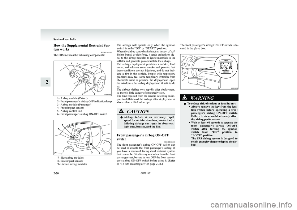
The SRS includes the following components:
1- Airbag module (Driver)
2- Front passenger’s airbag OFF indication lamp
3- Airbag module (Passenger)
4- Front impact sensors
5- Airbag control unit
6- Front passenger’s airbag ON-OFF switch
7- Side airbag modules
8- Side impact sensors
9- Curtain airbag modules
The airbags will operate only when the ignition
switch is in the “ON” or “START” position.
When the airbag control unit detect an impact of suf-
ficient frontal or side force, it sends an ignition sig-
nal to the airbag modules to ignite materials in the
inflator and generate gas and inflate the airbags.
The airbags deployment produces a sudden, loud
noise, and releases some smoke and powder, but
these conditions are not injurious, and do not indi-
cate a fire in the vehicle. People with respiratory
problems may feel some temporary irritation from
chemicals used to produce the deployment; open
the windows after airbag deployment, if safe to do
so.
The airbags deflate very rapidly after deployment,
so there is little danger of obscured vision.
The time required from the sensors detecting an im-
pact to deflation of the airbags after deployment is
shorter than a blink of an eye.CAUTIONl Airbags inflate at an extremely rapid
speed. In certain situations, contact with
inflating airbags can result in abrasions,
light cuts, bruises, and the like.Front passenger’s airbag ON-OFF
switch E00410100331
The front passenger’s airbag ON-OFF switch can
be used to disable the front passenger’s airbag. If
you have a rearward facing child restraint system
that cannot be fitted to any seat other than the front
passenger seat, be sure to turn OFF the front passen-
ger’s airbag ON-OFF switch before using it. (Refer
to “To turn an airbag off” on page 2-31.)
The front passenger’s airbag ON-OFF switch is lo-
cated in the glove box.WARNINGl To reduce risk of serious or fatal injury:
•Always remove the key from the igni-
tion switch before operating a front
passenger’s airbag ON-OFF switch.
Failure to do so could adversely affect
the airbag performance.
• Wait at least 60 seconds to operate the
front passenger’s airbag ON-OFF
switch after turning the ignition
switch from “ON” position to
“LOCK” position.
The SRS airbag system is designed to
retain enough voltage to deploy the air-
bag.
Seat and seat belts
2-30 OKTE13E1
2
Page 78 of 362
Front passenger’s airbag OFF indica-
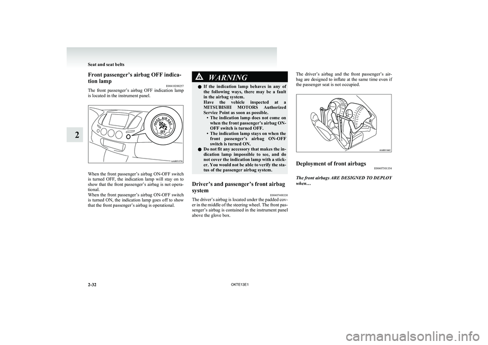
tion lamp E00410200257
The front passenger’s airbag OFF indication lamp
is located in the instrument panel.
When the front passenger’s airbag ON-OFF switch
is turned OFF, the indication lamp will stay on to
show that the front passenger’s airbag is not opera-
tional.
When the front passenger’s airbag ON-OFF switch
is turned ON, the indication lamp goes off to show
that the front passenger’s airbag is operational.
WARNINGl If the indication lamp behaves in any of
the following ways, there may be a fault
in the airbag system.
Have the vehicle inspected at a
MITSUBISHI MOTORS Authorized
Service Point as soon as possible. •The indication lamp does not come on
when the front passenger’s airbag ON-
OFF switch is turned OFF.
• The indication lamp stays on when the front passenger’s airbag ON-OFF
switch is turned ON.
l Do not fit any accessory that makes the in-
dication lamp impossible to see, and do
not cover the indication lamp with a stick-
er. You would not be able to verify the sta-
tus of the passenger airbag system.Driver’s and passenger’s front airbag
system E00407400330
The driver’s airbag is located under the padded cov-
er in the middle of the steering wheel. The front pas-
senger’s airbag is contained in the instrument panel
above the glove box.
The driver’s airbag and the front passenger’s air-
bag are designed to inflate at the same time even if
the passenger seat is not occupied.Deployment of front airbags E00407501354
The front airbags ARE DESIGNED TO DEPLOY
when…
Seat and seat belts
2-32 OKTE13E1
2
Page 81 of 362
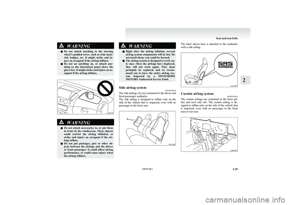
WARNINGlDo not attach anything to the steering
wheel’s padded cover, such as trim mate-
rial, badges, etc. It might strike and in-
jure an occupant if the airbag inflates.
l Do not set anything on, or attach any-
thing to, the instrument panel above the
glove box. It might strike and injure an oc-
cupant if the airbag inflates.WARNINGl Do not attach accessories to, or put them
in front of, the windscreen. These objects
could restrict the airbag inflation, or
strike and injure an occupant if the air-
bags inflate.
l Do not put packages, pets or other ob-
jects between the airbags and the driver
or front passenger. It could affect airbag
performance, or could cause injury when
the airbag inflates.WARNINGl Right after the airbag inflation, several
airbag system components will be hot. Do
not touch them; you could be burned.
l The airbag system is designed to work on-
ly once. Once the airbags have deployed,
they will not work again. They must
promptly be replaced, and we recom-
mend you to have the entire airbag sys-
tem inspected by a MITSUBISHI
MOTORS Authorized Service Point.Side airbag system E00407600563
The side airbags (A) are contained in the driver and
front passenger seatbacks.
The side airbag is designed to inflate only on the
side of the vehicle that is impacted, even with no
passenger in the front seat.
The label shown here is attached to the seatbacks
with a side airbag.Curtain airbag system E00409100474
The curtain airbags are contained in the front pil-
lars and roof side rail. The curtain airbag is de-
signed to inflate only on the side of the vehicle that
is impacted, even with no passenger in the front
seat or rear seat.
Seat and seat belts
2-35
OKTE13E1
2
Page 247 of 362
USB input terminal*E00761900015
You can connect your USB memory device or
iPod* to play music files stored in the USB memo-
ry device or iPod.
The following explains how to connect and remove
a USB memory device or iPod.
Refer to the following sections for details on how
to play music files:
Refer to “To play tracks from USB device” on
page 5-27.
*: “iPod” is a registered trademark of Apple Inc. in
the United States and other countries.How to connect a USB memory device E00762000202
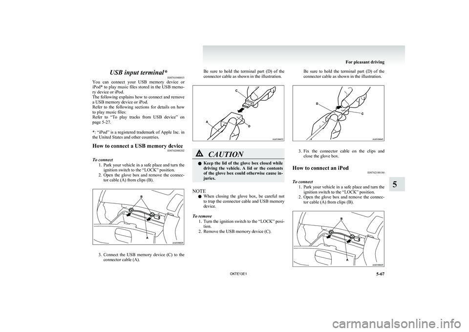
To connect
1.Park your vehicle in a safe place and turn the
ignition switch to the “LOCK” position.
2. Open the glove box and remove the connec-
tor cable (A) from clips (B).
3. Connect the USB memory device (C) to the
connector cable (A).
Be sure to hold the terminal part (D) of the
connector cable as shown in the illustration.CAUTIONl Keep the lid of the glove box closed while
driving the vehicle. A lid or the contents
of the glove box could otherwise cause in-
juries.
NOTE
l When closing the glove box, be careful not
to trap the connector cable and USB memory
device.
To remove 1.Turn the ignition switch to the “LOCK” posi-
tion.
2. Remove the USB memory device (C).
Be sure to hold the terminal part (D) of the
connector cable as shown in the illustration.
3. Fix the connector cable on the clips and
close the glove box.
How to connect an iPod E00762100186
To connect
1.Park your vehicle in a safe place and turn the
ignition switch to the “LOCK” position.
2. Open the glove box and remove the connec-
tor cable (A) from clips (B).
For pleasant driving
5-67
OKTE13E1
5
Page 248 of 362
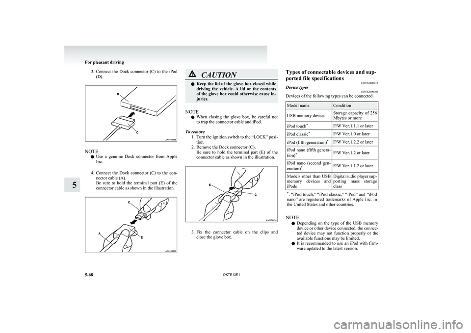
3.Connect the Dock connector (C) to the iPod
(D).
NOTE
l Use a genuine Dock connector from Apple
Inc.
4. Connect the Dock connector (C) to the con-
nector cable (A).
Be sure to hold the terminal part (E) of the
connector cable as shown in the illustration.
CAUTIONl Keep the lid of the glove box closed while
driving the vehicle. A lid or the contents
of the glove box could otherwise cause in-
juries.
NOTE
l When closing the glove box, be careful not
to trap the connector cable and iPod.
To remove 1.Turn the ignition switch to the “LOCK” posi-
tion.
2. Remove the Dock connector (C). Be sure to hold the terminal part (E) of the
connector cable as shown in the illustration.
3. Fix the connector cable on the clips and
close the glove box.
Types of connectable devices and sup-
ported file specifications E00762200015Device typesE00762300306
Devices of the following types can be connected.
Model nameConditionUSB memory deviceStorage capacity of 256
Mbytes or moreiPod touch *F/W Ver.1.1.1 or lateriPod classic *F/W Ver.1.0 or lateriPod (fifth generation) *F/W Ver.1.2.2 or lateriPod nano (fifth genera-
tion) *F/W Ver.1.2 or lateriPod nano (second gen-
eration) *F/W Ver.1.1.2 or laterModels other than USB
memory devices and
iPodsDigital audio player sup-
porting mass storage
class* : “iPod touch,” “iPod classic,” “iPod” and “iPod
nano” are registered trademarks of Apple Inc. in
the United States and other countries.
NOTE
l Depending on the type of the USB memory
device or other device connected, the connec-
ted device may not function properly or the
available functions may be limited.
l It is recommended to use an iPod with firm-
ware updated to the latest version.
For pleasant driving
5-68 OKTE13E1
5
Page 256 of 362
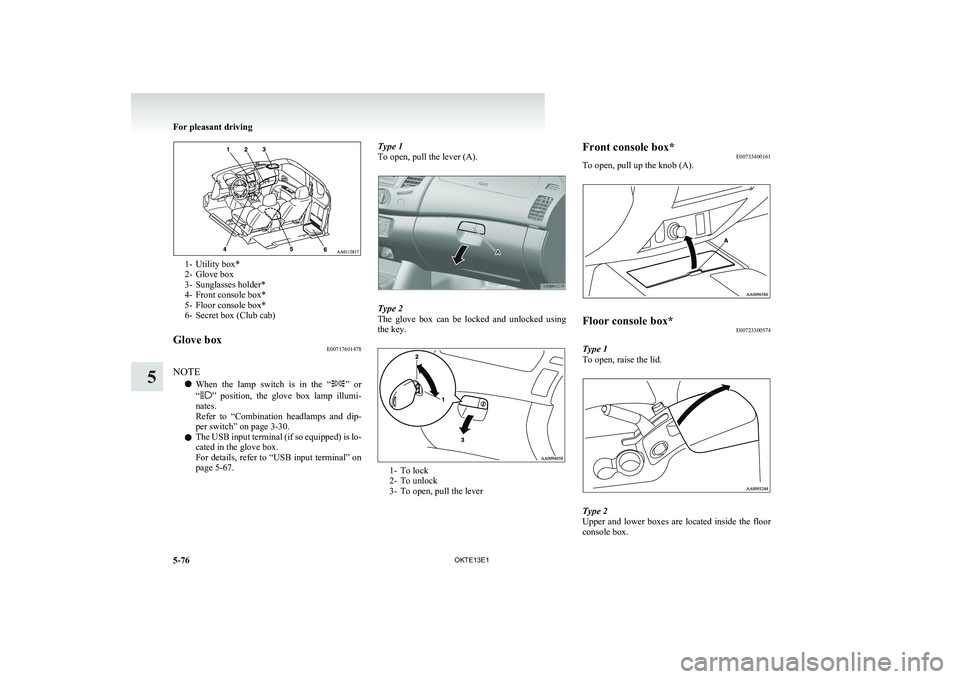
1- Utility box*
2- Glove box
3- Sunglasses holder*
4- Front console box*
5- Floor console box*
6- Secret box (Club cab)
Glove box E00717601478
NOTE
l When the lamp switch is in the “
”
or
“” position, the glove box lamp illumi-
nates.
Refer to “Combination headlamps and dip-
per switch” on page 3-30.
l The USB input terminal (if so equipped) is lo-
cated in the glove box.
For details, refer to “USB input terminal” on
page 5-67.
Type 1
To open, pull the lever (A).
Type 2
The glove box can be locked and unlocked using
the key.
1- To lock
2- To unlock
3- To open, pull the lever
Front console box* E00733400161
To open, pull up the knob (A).Floor console box* E00723300574
Type 1
To open, raise the lid.
Type 2
Upper and lower boxes are located inside the floor
console box.
For pleasant driving
5-76 OKTE13E1
5