jump start MITSUBISHI L200 2013 Owner's Manual (in English)
[x] Cancel search | Manufacturer: MITSUBISHI, Model Year: 2013, Model line: L200, Model: MITSUBISHI L200 2013Pages: 362, PDF Size: 21.07 MB
Page 143 of 362
Automatic transmission SportsMode 4A/T, 5A/T E00603200710
NOTE l During running-in period or immediately af-
ter reconnection of the battery cable, there
may be a case where gear shifts are not made
smoothly. This does not indicate a faulty trans-
mission.
Gear shifts will become smooth after the trans-
mission has been shifted several times by the
electronic control system.Selector lever operation E00603301082
The transmission has 4 forward gears (4A/T), 5 for-
ward gears (5A/T) and 1 reverse gear.
The individual gears are selected automatically, de-
pending on the position of the gear selector lever,
the speed of the vehicle and the position of the ac-
celerator pedal.
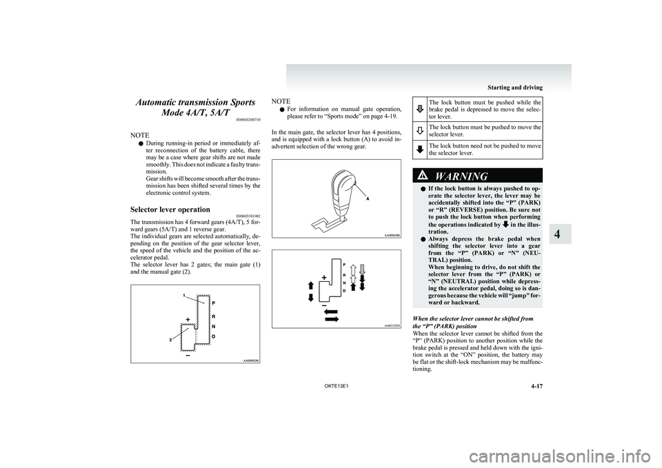
The selector lever has 2 gates; the main gate (1)
and the manual gate (2).
NOTE
l For information on manual gate operation,
please refer to “Sports mode” on page 4-19.
In the main gate, the selector lever has 4 positions,
and is equipped with a lock button (A) to avoid in-
advertent selection of the wrong gear.The lock button must be pushed while the
brake pedal is depressed to move the selec-
tor lever.The lock button must be pushed to move the
selector lever.The lock button need not be pushed to move
the selector lever.WARNINGl If the lock button is always pushed to op-
erate the selector lever, the lever may be
accidentally shifted into the “P” (PARK)
or “R” (REVERSE) position. Be sure not
to push the lock button when performing
the operations indicated by
in the illus-
tration.
l Always depress the brake pedal when
shifting the selector lever into a gear
from the “P” (PARK) or “N” (NEU-
TRAL) position.
When beginning to drive, do not shift the
selector lever from the “P” (PARK) or
“N” (NEUTRAL) position while depress-
ing the accelerator pedal, doing so is dan-
gerous because the vehicle will “jump” for-
ward or backward.
When the selector lever cannot be shifted from
the “P” (PARK) position
When the selector lever cannot be shifted from the
“P” (PARK) position to another position while the
brake pedal is pressed and held down with the igni-
tion switch at the “ON” position, the battery may
be flat or the shift-lock mechanism may be malfunc-
tioning.
Starting and driving
4-17
OKTE13E1
4
Page 165 of 362
Limited-slip differential*E00606900037
A limited-slip differential is applied for the rear
wheel differential only. The features of this limited-
slip differential are described below:
Just as with a conventional differential, the wheel
on one side is allowed to turn at a different speed
from the wheel on the other side when the vehicle
is cornering. The difference between the limited-
slip differential and a conventional differential is
that if the wheel on one side of the vehicle loses trac-
tion, a greater amount of torque is applied to the
wheel on the other side to improve traction.
NOTE l Even if there is a difference in the amount of
traction the wheels can get, if both of them
are spinning, the limited-slip differential will
not be effective.CAUTIONl Never start the engine while one of the
rear wheels is jacked up and the other in
contact with the ground; doing so may
cause the vehicle to jump forward.
l When attempting to extract the vehicle
from snow, mud, etc., and the engine is
run continuously at high speed, the limi-
ted-slip differential will be adversely af-
fected.Braking E00607001928
All the parts of the brake system are critical to safe-
ty. We recommend you to have the vehicle
checked at regular intervals according to the serv-
ice booklet.CAUTIONl Avoid driving habits that cause heavy
braking and never “ride” the brakes by
resting your foot on the brake pedal
while driving.
It causes brake overheating and fade.
Brake system
The service brake is divided into two brake cir-
cuits. And your vehicle is equipped with power
brakes. If one brake circuit fails, the other is availa-
ble to stop the vehicle. If you should lose the pow-
er assist for some reason, the brakes will still work.
In these situations, even if the brake pedal moves
down to the very end of its possible stroke or re-
sists being depressed, keep depressing the brake ped-
al down harder and further than usual; stop driving
as soon as possible and have the brake system re-
paired.
WARNINGl Do not turn off the engine while your ve-
hicle is in motion. If you turn off the en-
gine while driving, the power assistance
for the braking system will stop working
and your brakes will not work effectively.WARNINGl If the power assist is lost or if either
brake hydraulic system stops working
properly, have your vehicle checked im-
mediately.
Warning lamp
The brake warning lamp illuminates to indicate a
fault in the braking system. Refer to “Brake warn-
ing lamp” on page 3-08.
When brakes are wet
Check the brake system while driving at a low
speed immediately after starting, especially when
the brakes are wet, to confirm they work normally.
A film of water can be formed on the brake discs
or brake drums and prevent normal braking after
driving in heavy rain or through large puddles, or
after the vehicle is washed. If this occurs, dry the
brakes out by driving slowly while lightly depress-
ing the brake pedal.
When driving downhill
It is important to take advantage of the engine brak-
ing by shifting to a lower shift position while driv-
ing on steep downhill roads in order to prevent the
brakes from overheating.
Starting and driving
4-39
OKTE13E1
4
Page 262 of 362
If the vehicle breaks downE00800101166
If the vehicle breaks down on the road, move it to
the shoulder and use the hazard warning flashers and/
or the warning triangle etc.
Refer to “Hazard warning flasher switch” on page
3-34.
If the engine stops/fails
Vehicle operation and control are affected if the en-
gine stops.
Before moving the vehicle to a safe area, be aware
of the following:
l The brake booster becomes inoperative and
the pedal effort will increase. Press down the
brake pedal harder than usual.
l Since the power steering pump is no longer
operative, the steering wheel feels heavy
when turning it.Emergency starting E00800502112
If the engine cannot be started because the battery
is weak or dead, the battery from another vehicle
can be used with jumper cables to start the engine.WARNINGl To start the engine using jumper cables
connected from another vehicle, perform
the correct procedures according to the in-
struction manual. Incorrect procedures
could result in a fire or explosion or dam-
age to the vehicles.
1. Get the vehicles close enough so the jumper
cables can reach, but be sure the vehicles
aren’t touching each other.
If they are, it could cause a ground connec-
tion you don’t want. The vehicle will not
start, and the bad grounding could damage
the electrical systems.
CAUTIONl Check the other vehicle. It must have a 12-
volt battery.
If the other system isn’t 12-volt, shorting
can damage both vehicles.
2. You could be injured if the vehicles move.
Set the parking brake firmly on each vehicle.
Put an automatic transmission in “P”
(PARK) or a manual transmission in “N”
(Neutral). Turn off the ignition switch.
WARNINGl Turn off the ignition on both vehicles be-
forehand.
Make sure that the cables or your clothes
cannot be caught by the fan or drive belt.
Personal injury could result.
NOTE
l Turn off all lamps, heater and other electrical
loads. This will avoid sparks and help save
both batteries.
3. Make sure battery electrolyte is at the proper
level.
Refer to “Battery” on page 8-10.
WARNINGl If electrolyte fluid is not visible, or ap-
pears to be frozen, Do Not Attempt Jump
Starting!
A battery might rupture or explode if the
temperature is below the freezing point
or if it is not filled to the proper level.
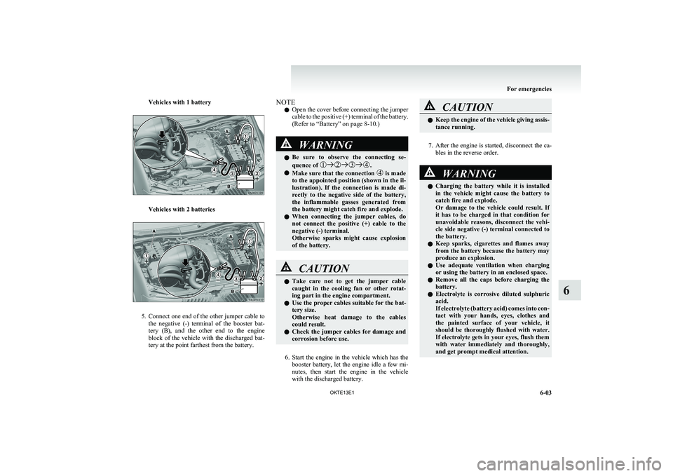
4. Connect one end of one jumper cable to the
positive (+) terminal of the discharged bat-
tery (A), and the other end to the positive (+)
terminal of the booster battery (B).
For emergencies
6-02 OKTE13E1
6
Page 263 of 362
Vehicles with 1 battery
Vehicles with 2 batteries
5.Connect one end of the other jumper cable to
the negative (-) terminal of the booster bat-
tery (B), and the other end to the engine
block of the vehicle with the discharged bat-
tery at the point farthest from the battery.
NOTE
l Open the cover before connecting the jumper
cable to the positive (+) terminal of the battery.
(Refer to “Battery” on page 8-10.)WARNINGl Be sure to observe the connecting se-
quence of .
l Make sure that the connection is made
to the appointed position (shown in the il-
lustration). If the connection is made di-
rectly to the negative side of the battery,
the inflammable gasses generated from
the battery might catch fire and explode.
l When connecting the jumper cables, do
not connect the positive (+) cable to the
negative (-) terminal.
Otherwise sparks might cause explosion
of the battery.
CAUTIONl Take care not to get the jumper cable
caught in the cooling fan or other rotat-
ing part in the engine compartment.
l Use the proper cables suitable for the bat-
tery size.
Otherwise heat damage to the cables
could result.
l Check the jumper cables for damage and
corrosion before use.
6. Start the engine in the vehicle which has the
booster battery, let the engine idle a few mi-
nutes, then start the engine in the vehicle
with the discharged battery.
CAUTIONl Keep the engine of the vehicle giving assis-
tance running.
7. After the engine is started, disconnect the ca-
bles in the reverse order.
WARNINGl Charging the battery while it is installed
in the vehicle might cause the battery to
catch fire and explode.
Or damage to the vehicle could result. If
it has to be charged in that condition for
unavoidable reasons, disconnect the vehi-
cle side negative (-) terminal connected to
the battery.
l Keep sparks, cigarettes and flames away
from the battery because the battery may
produce an explosion.
l Use adequate ventilation when charging
or using the battery in an enclosed space.
l Remove all the caps before charging the
battery.
l Electrolyte is corrosive diluted sulphuric
acid.
If electrolyte (battery acid) comes into con-
tact with your hands, eyes, clothes and
the painted surface of your vehicle, it
should be thoroughly flushed with water.
If electrolyte gets in your eyes, flush them
with water immediately and thoroughly,
and get prompt medical attention.
For emergencies
6-03
OKTE13E1
6
Page 350 of 362
Switch 1-08
Electrical system 9-16
Electronic immobilizer (Anti-theft starting sys-
tem) 1-03
Emergency starting 6-02
Engine specifications 9-14
Engine Coolant 8-06,9-20
Number 9-02
Oil 8-04,9-20
Overheating 6-04
Specifications 9-14
Used engine oils safety instructions and disposal
information 05
Water temperature gauge 3-05
Error codes 5-42
Exterior and interior lamp operation 8-18
F
First-aid kit and warning triangle band for secur-
ing 5-80
Floor console box 5-76
Fluid Automatic transmission fluid 8-07,9-20
Brake fluid 8-08,9-20
Clutch fluid 8-09,9-20
Engine coolant 8-06,9-20
Power steering fluid 8-09,9-20
Washer fluid 8-08,9-20
For cold and snowy weather 8-19
Front console box 5-76
Front fog lamps Bulb capacity 8-24
Indication lamp 3-07
Replacement 8-28
Switch 3-34
Front room lamp Bulb capacity 8-25
Replacement 8-32
Front seat 2-03
Front turn-signal lamps Bulb capacity 8-24
Replacement 8-27
Fuel consumption 9-19
Fuel Filling the fuel tank 02
Fuel filter indication lamp 3-07
Fuel gauge 3-04
Fuel selection 02
Low fuel warning lamp 3-04
Modification/alterations to the electrical or fuel
systems 04
Tank capacity 02
Fuses 8-20
Fusible links 8-19
G
Gauges 3-02
General maintenance 8-18
General vehicle data 9-03
Genuine parts 05
Glove box 5-76
Glove box lamp Bulb capacity 8-24
Replacement 8-33
H
Handling of compact discs 5-48
Hazard warning flasher switch 3-34
Hazard warning indication lamps 3-07
Head restraints 2-08
Headlamp levelling switch 3-32
Headlamps Bulb capacity 8-24
Headlamp flasher 3-31
Replacement 8-25
Switch 3-30
Washer switch 3-39
Heated mirror 4-10
Heated seats 2-06
Heater 5-03
High-mounted stop lamp Bulb capacity 8-24
Replacement 8-31
Hinges and latches lubrication 8-19
Hooks Coat hook 5-80
Convenient hook 5-80
Horn switch 3-40
I
If the vehicle breaks down 6-02
Ignition switch 4-10
Indication and warning lamps 3-06
Indication lamps 3-07
Inside rear-view mirror 4-08
Inspection and maintenance following rough road
operation 4-37
Installation of accessories 04
Instruments 3-02
Interior lamps 5-73
J
Jack handle 6-12Storage 6-07
Jacking up the vehicle 6-13
Jack Storage 6-07
Jump starting (Emergency starting) 6-02
Alphabetical index
2