tow MITSUBISHI L200 2017 (in English) Owner's Guide
[x] Cancel search | Manufacturer: MITSUBISHI, Model Year: 2017, Model line: L200, Model: MITSUBISHI L200 2017Pages: 426, PDF Size: 14.12 MB
Page 338 of 426
CAUTIONlNever tow an automatic transmission vehicle
with the front wheels up (and the rear wheels
on the ground) (Type B) when the automatic transmission fluid level is low. This may
cause serious and expensive damage to the
transmission.
Towing with rear wheels off the
ground (Type C)
Place the gearshift lever in the “N” (Neutral)
position (manual transmission) or the selector
lever in the “N” (NEUTRAL) position (auto- matic transmission). Turn the ignition switch
to the “ACC” position or put the operation mode in ACC and secure the steering wheel
in a straight-ahead position with a rope or tie- down strap. Never place the ignition switch
in the “LOCK” position or put the operation
mode in OFF when towing.
Emergency towing
If towing service is not available in an emer- gency, your vehicle may be temporarily tow-ed by a rope secured to the towing hook.
If your vehicle is to be towed by another ve-
hicle or if your vehicle tows another vehicle, pay careful attention to the following points.
If your vehicle is to be towed by
another vehicle
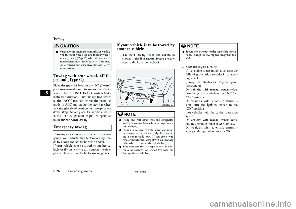
1. The front towing hooks are located as
shown in the illustration. Secure the tow
rope to the front towing hook.
NOTEl Using any part other than the designated
towing hooks could result in damage to the
vehicle body.
l Using a wire rope or metal chain can result
in damage to the vehicle body. It is best to
use a non-metallic rope. If you use a wire rope or metal chain, wrap it with cloth at any
point where it touches the vehicle body.
l Take care that the tow rope is kept as hori-
zontal as possible. An angled tow rope can damage the vehicle body.NOTEl Secure the tow rope to the same side towing
hook, to keep the tow rope as straight as pos-
sible.
2. Keep the engine running.
If the engine is not running, perform the
following operation to unlock the steer- ing wheel.
[Except for vehicles with keyless opera-
tion system]
On vehicles with manual transmission, turn the ignition switch to the “ACC” or
“ON” position.
On vehicles with automatic transmis- sion, turn the ignition switch to the
“ON” position.
[For vehicles with the keyless operation
system]
On vehicles with manual transmission, put the operation mode in ACC or ON.On vehicles with automatic transmis- sion, put the operation mode in ON.
Towing
8-26OKTE17E1For emergencies8
Page 339 of 426
NOTElFor vehicles equipped with the Auto Stop &
Go (AS&G) system, press the “Auto Stop &Go (AS&G) OFF” switch to deactivate theAuto Stop & Go (AS&G) system before stopping the vehicle.
Refer to “To deactivate” on page 6-26.WARNINGl When the engine is not running, the brake
booster and power steering pump do notoperate. This means higher brake depres-sion force and higher steering effort arerequired. Therefore, vehicle operation is
very difficult.CAUTIONl Do not leave the ignition switch in the
“LOCK” position or the operation mode in
OFF. The steering wheel will lock, causing loss of control.
3. Place the gearshift lever in the “N”
(Neutral) position (manual transmission) or the selector lever in the “N” (NEU-
TRAL) position (automatic transmis-
sion).
4. On 4WD vehicles, set the drive mode se-
lector to the “2H” position.
5. Turn on the hazard warning lamps if re-
quired by law. (Follow the local driving
laws and regulations.)
6. During towing make sure that close con-
tact is maintained between the drivers of
both vehicles, and that the vehicles trav- el at low speed.WARNINGl Avoid sudden braking, acceleration and
steering wheel movements; such driving operation could cause damage to the tow-
ing hook or tow rope.
People in the vicinity could be injured as a
result.
l When going down a long slope, the brakes
may overheat, reducing effectiveness. Have your vehicle transported by a tow
truck.CAUTIONl The person in the vehicle being towed must
pay attention to the brake lamps of the tow- ing vehicle and make sure the rope never be-
comes slack.CAUTIONl When a vehicle with an automatic transmis-
sion is to be towed by another vehicle with
all the wheels on the ground, make sure that the towing speed and distance given below
are never exceeded, avoiding damage to the
transmission.
Towing speed: 30 km/h (19 mph)
Towing distance: 80 km (50 miles)
For the towing speed and the towing dis- tance, follow the local driving laws and reg- ulations.
If your vehicle tows another ve-
hicle (vehicles with rear towing hook only)
The rear towing hook is located as shown inthe illustration. Secure the tow rope to the
rear towing hook.
Towing
8-27OKTE17E1For emergencies8
Page 340 of 426
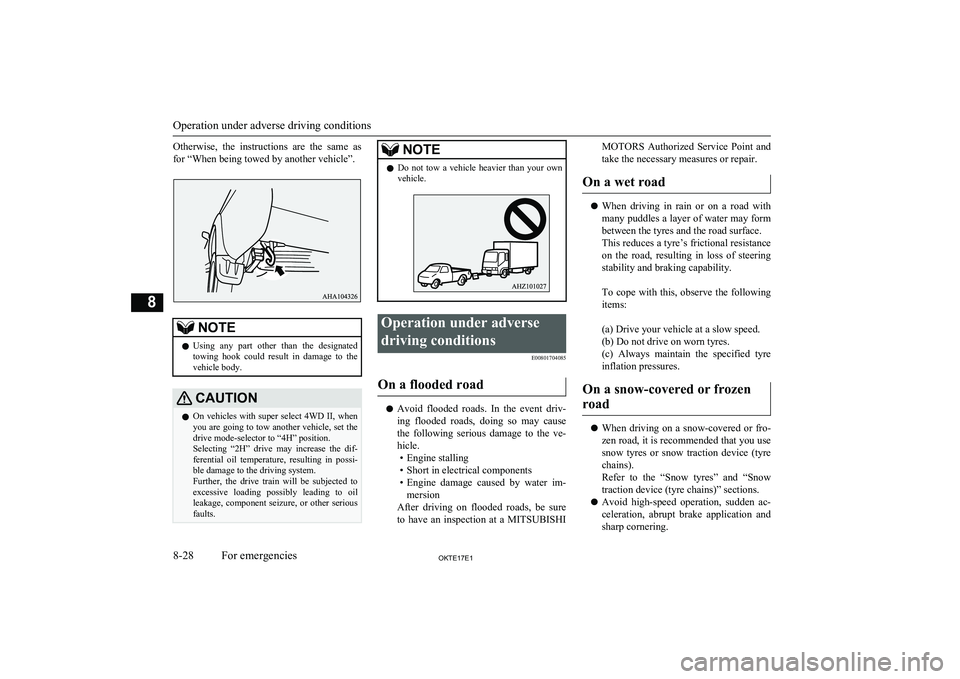
Otherwise, the instructions are the same as
for “When being towed by another vehicle”.NOTEl Using any part other than the designated
towing hook could result in damage to thevehicle body.CAUTIONl On vehicles with super select 4WD II, when
you are going to tow another vehicle, set the drive mode-selector to “4H” position.Selecting “2H” drive may increase the dif-
ferential oil temperature, resulting in possi-
ble damage to the driving system.
Further, the drive train will be subjected to excessive loading possibly leading to oilleakage, component seizure, or other serious
faults.NOTEl Do not tow a vehicle heavier than your own
vehicle.Operation under adverse
driving conditions E00801704085
On a flooded road
lAvoid flooded roads. In the event driv-
ing flooded roads, doing so may causethe following serious damage to the ve-
hicle. • Engine stalling
• Short in electrical components
• Engine damage caused by water im-
mersion
After driving on flooded roads, be sure
to have an inspection at a MITSUBISHI
MOTORS Authorized Service Point and
take the necessary measures or repair.
On a wet road
l When driving in rain or on a road with
many puddles a layer of water may form
between the tyres and the road surface.
This reduces a tyre’s frictional resistance
on the road, resulting in loss of steering stability and braking capability.
To cope with this, observe the following items:
(a) Drive your vehicle at a slow speed. (b) Do not drive on worn tyres. (c) Always maintain the specified tyre
inflation pressures.
On a snow-covered or frozen road
l When driving on a snow-covered or fro-
zen road, it is recommended that you use snow tyres or snow traction device (tyre chains).
Refer to the “Snow tyres” and “Snow
traction device (tyre chains)” sections.
l Avoid high-speed operation, sudden ac-
celeration, abrupt brake application and
sharp cornering.
Operation under adverse driving conditions
8-28OKTE17E1For emergencies8
Page 352 of 426
BonnetE01000304126
To open
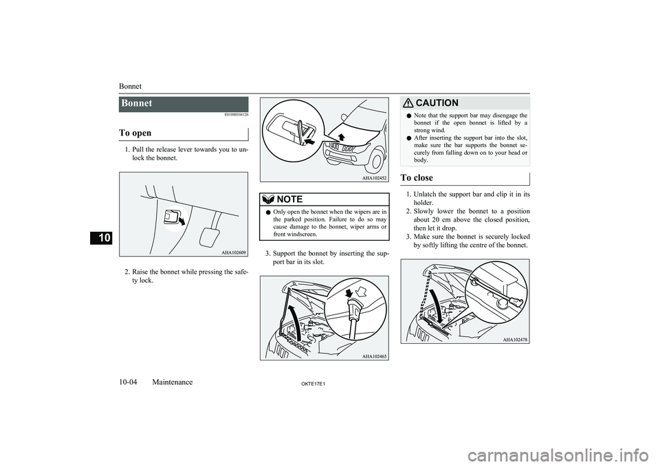
1. Pull the release lever towards you to un-
lock the bonnet.
2. Raise the bonnet while pressing the safe-
ty lock.
NOTEl Only open the bonnet when the wipers are in
the parked position. Failure to do so may
cause damage to the bonnet, wiper arms or
front windscreen.
3. Support the bonnet by inserting the sup-
port bar in its slot.
CAUTIONl Note that the support bar may disengage the
bonnet if the open bonnet is lifted by astrong wind.
l After inserting the support bar into the slot,
make sure the bar supports the bonnet se-
curely from falling down on to your head or body.
To close
1. Unlatch the support bar and clip it in its
holder.
2. Slowly lower the bonnet to a position
about 20 cm above the closed position,
then let it drop.
3. Make sure the bonnet is securely locked
by softly lifting the centre of the bonnet.
Bonnet
10-04OKTE17E1Maintenance10
Page 360 of 426
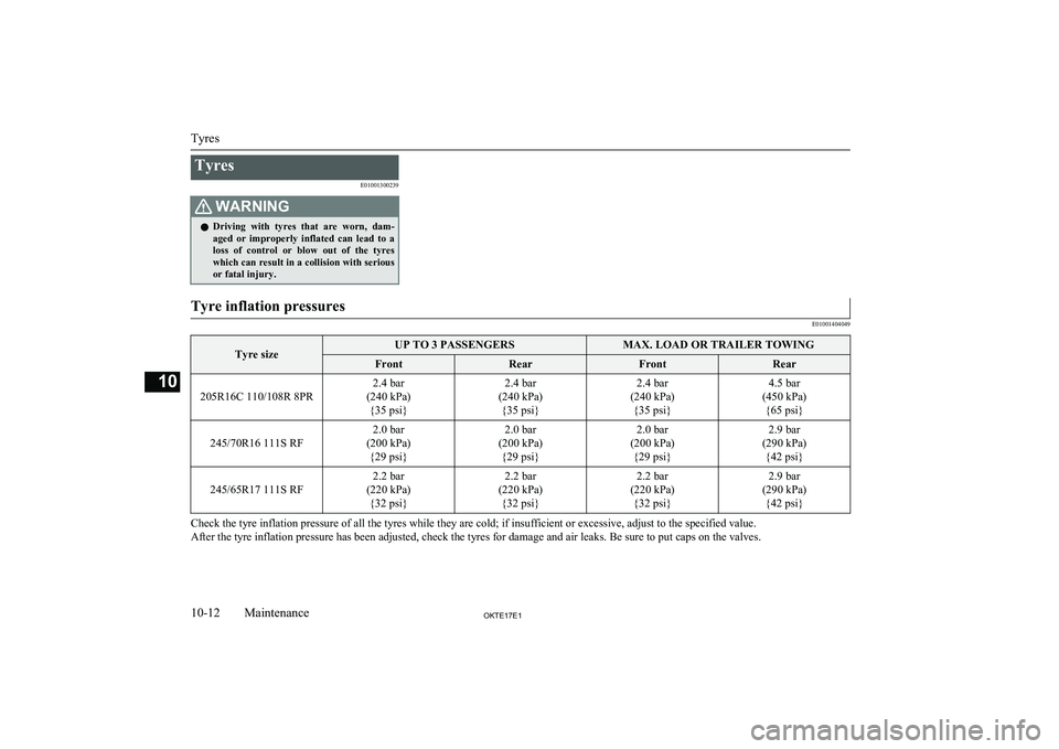
TyresE01001300239WARNINGlDriving with tyres that are worn, dam-
aged or improperly inflated can lead to a
loss of control or blow out of the tyres which can result in a collision with serious
or fatal injury.Tyre inflation pressures
E01001404049Tyre sizeUP TO 3 PASSENGERSMAX. LOAD OR TRAILER TOWINGFrontRearFrontRear
205R16C 110/108R 8PR
2.4 bar
(240 kPa) {35 psi}2.4 bar
(240 kPa) {35 psi}2.4 bar
(240 kPa) {35 psi}4.5 bar
(450 kPa) {65 psi}
245/70R16 111S RF
2.0 bar
(200 kPa) {29 psi}2.0 bar
(200 kPa) {29 psi}2.0 bar
(200 kPa) {29 psi}2.9 bar
(290 kPa) {42 psi}
245/65R17 111S RF
2.2 bar
(220 kPa) {32 psi}2.2 bar
(220 kPa) {32 psi}2.2 bar
(220 kPa) {32 psi}2.9 bar
(290 kPa) {42 psi}
Check the tyre inflation pressure of all the tyres while they are cold; if insufficient or excessive, adjust to the specified value.
After the tyre inflation pressure has been adjusted, check the tyres for damage and air leaks. Be sure to put caps on the valves.
Tyres
10-12OKTE17E1Maintenance10
Page 372 of 426
3- Glove box lamp: 1.4 WHeadlamps (halogen bulb)
E01003502532
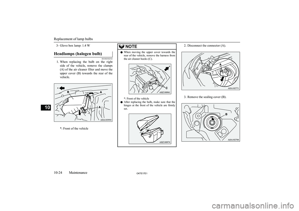
1.When replacing the bulb on the right
side of the vehicle, remove the clamps
(A) of the air cleaner filter and move the upper cover (B) towards the rear of the
vehicle.
*: Front of the vehicle
NOTEl When moving the upper cover towards the
rear of the vehicle, remove the harness fromthe air cleaner hooks (C).
*: Front of the vehicle
l After replacing the bulb, make sure that the
hinges at the front of the vehicle are firmly
set.
2. Disconnect the connector (A).
3. Remove the sealing cover (B).
Replacement of lamp bulbs
10-24OKTE17E1Maintenance10
Page 373 of 426
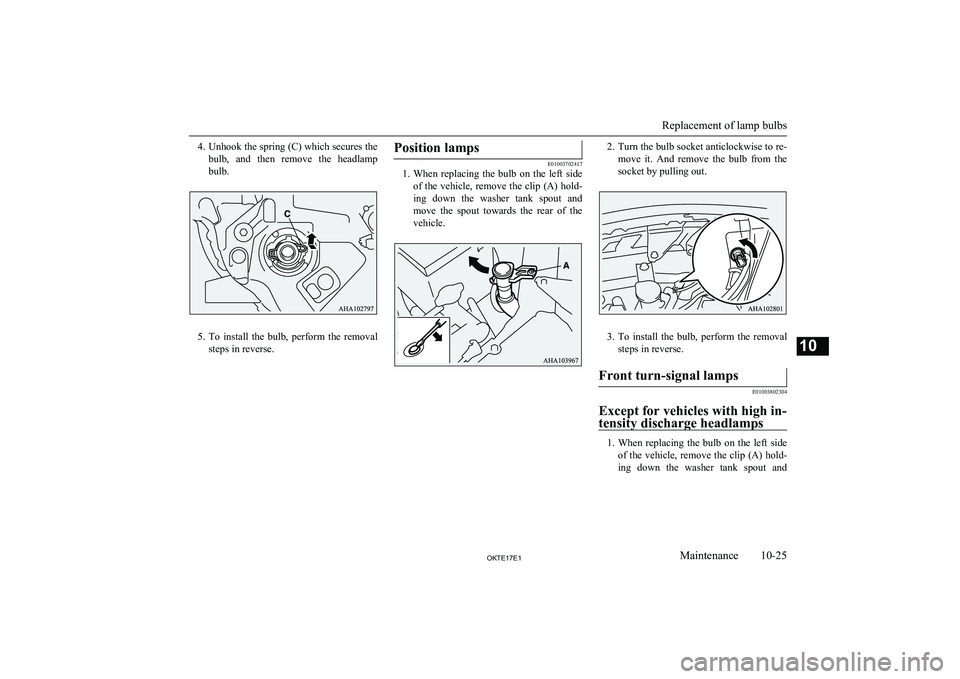
4.Unhook the spring (C) which secures the
bulb, and then remove the headlamp bulb.
5. To install the bulb, perform the removal
steps in reverse.
Position lamps
E01003702417
1. When replacing the bulb on the left side
of the vehicle, remove the clip (A) hold-
ing down the washer tank spout and
move the spout towards the rear of the vehicle.
2. Turn the bulb socket anticlockwise to re-
move it. And remove the bulb from the
socket by pulling out.
3. To install the bulb, perform the removal
steps in reverse.
Front turn-signal lamps
E01003802304
Except for vehicles with high in- tensity discharge headlamps
1. When replacing the bulb on the left side
of the vehicle, remove the clip (A) hold- ing down the washer tank spout and
Replacement of lamp bulbs
10-25OKTE17E1Maintenance10
Page 374 of 426
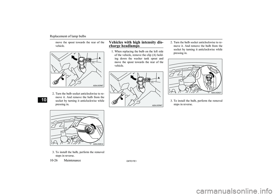
move the spout towards the rear of the
vehicle.
2. Turn the bulb socket anticlockwise to re-
move it. And remove the bulb from the
socket by turning it anticlockwise while pressing in.
3. To install the bulb, perform the removal
steps in reverse.
Vehicles with high intensity dis-
charge headlamps
1. When replacing the bulb on the left side
of the vehicle, remove the clip (A) hold- ing down the washer tank spout and
move the spout towards the rear of the vehicle.
2. Turn the bulb socket anticlockwise to re-
move it. And remove the bulb from the
socket by turning it anticlockwise while pressing in.
3. To install the bulb, perform the removal
steps in reverse.
Replacement of lamp bulbs
10-26OKTE17E1Maintenance10
Page 376 of 426
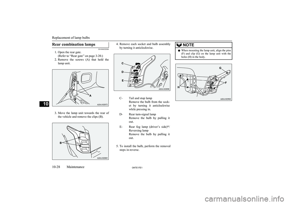
Rear combination lamps
E01004202884
1. Open the rear gate.
(Refer to “Rear gate” on page 3-20.)
2. Remove the screws (A) that hold the
lamp unit.
3. Move the lamp unit towards the rear of
the vehicle and remove the clips (B).
4. Remove each socket and bulb assembly
by turning it anticlockwise.C-Tail and stop lamp
Remove the bulb from the sock- et by turning it anticlockwise
while pressing in.D-Rear turn-signal lamp
Remove the bulb by pulling it
out.E-Rear fog lamp (driver’s side)*/ Reversing lamp
Remove the bulb by pulling it out.
5. To install the bulb, perform the removal
steps in reverse.
NOTEl When mounting the lamp unit, align the pins
(F) and clip (G) on the lamp unit with the
holes (H) in the body.
Replacement of lamp bulbs
10-28OKTE17E1Maintenance10
Page 392 of 426
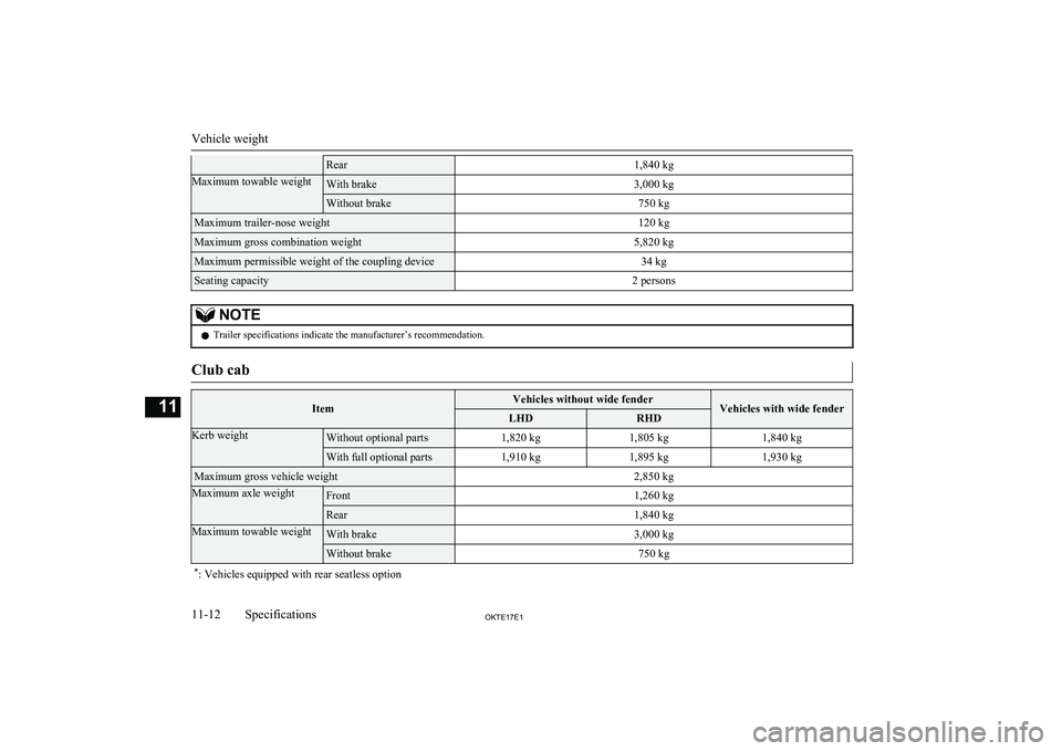
Rear1,840 kgMaximum towable weightWith brake3,000 kgWithout brake750 kgMaximum trailer-nose weight120 kgMaximum gross combination weight5,820 kgMaximum permissible weight of the coupling device34 kgSeating capacity2 personsNOTElTrailer specifications indicate the manufacturer’s recommendation.Club cabItemVehicles without wide fenderVehicles with wide fenderLHDRHDKerb weightWithout optional parts1,820 kg1,805 kg1,840 kgWith full optional parts1,910 kg1,895 kg1,930 kgMaximum gross vehicle weight2,850 kgMaximum axle weightFront1,260 kgRear1,840 kgMaximum towable weightWith brake3,000 kgWithout brake750 kg*
: Vehicles equipped with rear seatless option
Vehicle weight
11-12OKTE17E1Specifications11