brake MITSUBISHI LANCER 2006 User Guide
[x] Cancel search | Manufacturer: MITSUBISHI, Model Year: 2006, Model line: LANCER, Model: MITSUBISHI LANCER 2006Pages: 800, PDF Size: 45.03 MB
Page 161 of 800
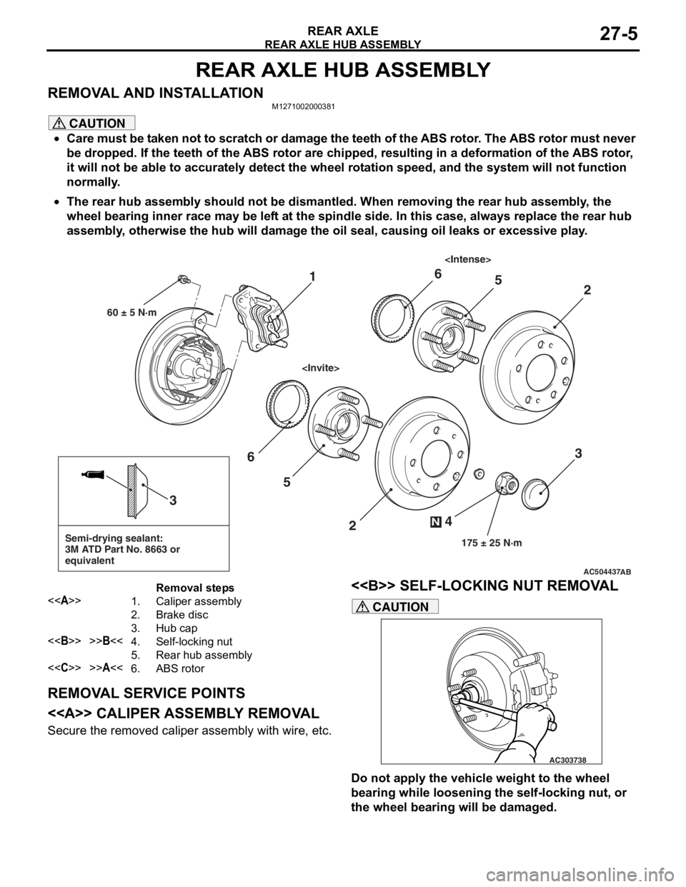
REAR AXLE HUB ASSEMBLY
REAR AXLE27-5
REAR AXLE HUB ASSEMBLY
REMOVAL AND INSTALLATIONM1271002000381
CAUTION
•Care must be taken not to scratch or damage the teeth of the ABS rotor. The ABS rotor must never
be dropped. If the teeth of the ABS rotor are chipped, resulting in a deformation of the ABS rotor,
it will not be able to accurately detect the wheel rotation speed, and the system will not function
normally.
•
AC504437
Semi-drying sealant:
3M ATD Part No. 8663 or
equivalent
2
3
5
6
4
N
175 ± 25 N·m
3
AB
1
60 ± 5 N·m
2
56
Removal steps
<>1.Caliper assembly
2.Brake disc
3.Hub cap
<>>>B<<4.Self-locking nut
5.Rear hub assembly
<
The rear hub assembly should not be dismantled. When removing the rear hub assembly, the
wheel bearing inner race may be left at the spindle side. In this case, always replace the rear hub
assembly, otherwise the hub will damage the oil seal, causing oil leaks or excessive play.
REMOVAL SERVICE POINTS
<> CALIPER ASSEMBLY REMOVAL
Secure the removed caliper assembly with wire, etc.
<> SELF-LOCKING NUT REMOVAL
AC303738
CAUTION
Do not apply the vehicle weight to the wheel
bearing while loosening the self-locking nut, or
the wheel bearing will be damaged.
Page 189 of 800
STRUT ASSEMBLY
FRONT SUSPENSION33-7
LOWER ARM BALL JOINT AXIAL PLAY
CHECK
M1332011300074
1. Raise the vehicle.
2. Remove the stabilizer link from the lower arm.
3. Move the lower arm up and down with your hands to check for an excessive play in the axial
direction of the ball joint. If there is an excessive
play, replace the lower arm assembly.
LOWER ARM BALL JOINT COVER
CHECK
M1332008600321
1. Press the lower arm ball joint cover with your finger to check that there are no cracks or
damage in the lower arm ball joint cover.
2. If the lower arm ball joint cover is cracked or damaged, replace the lower arm assembly.
NOTE: If the lower arm ball joint cover is cracked
or damaged, it is possible that there may also be
damage to the ball joint.
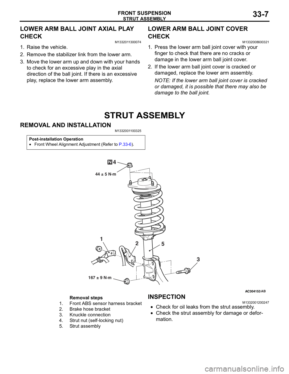
STRUT ASSEMBLY
REMOVAL AND INSTALLATION
M1332001100325
Post-installation Operation
•Front Wheel Alignment Adjustment (Refer to P.33-6).
AC304153
44 ± 5 N·m
1 2
3
4
N
AB
167 ± 9 N·m
5
Removal steps
1.Front ABS sensor
harness bracket
2.Brake hose bracket
3.Knuckle connection
4.Strut nut (self-locking nut)
5.Strut assembly
INSPECTION
M13320012 0024 7
•Check for oil leaks fro m the stru t assemb ly .
•Check the stru t assemb ly for damage o r defor-
mation.
Page 210 of 800
TRAILING ARM ASSEMBLY
REAR SUSPENSION34-12
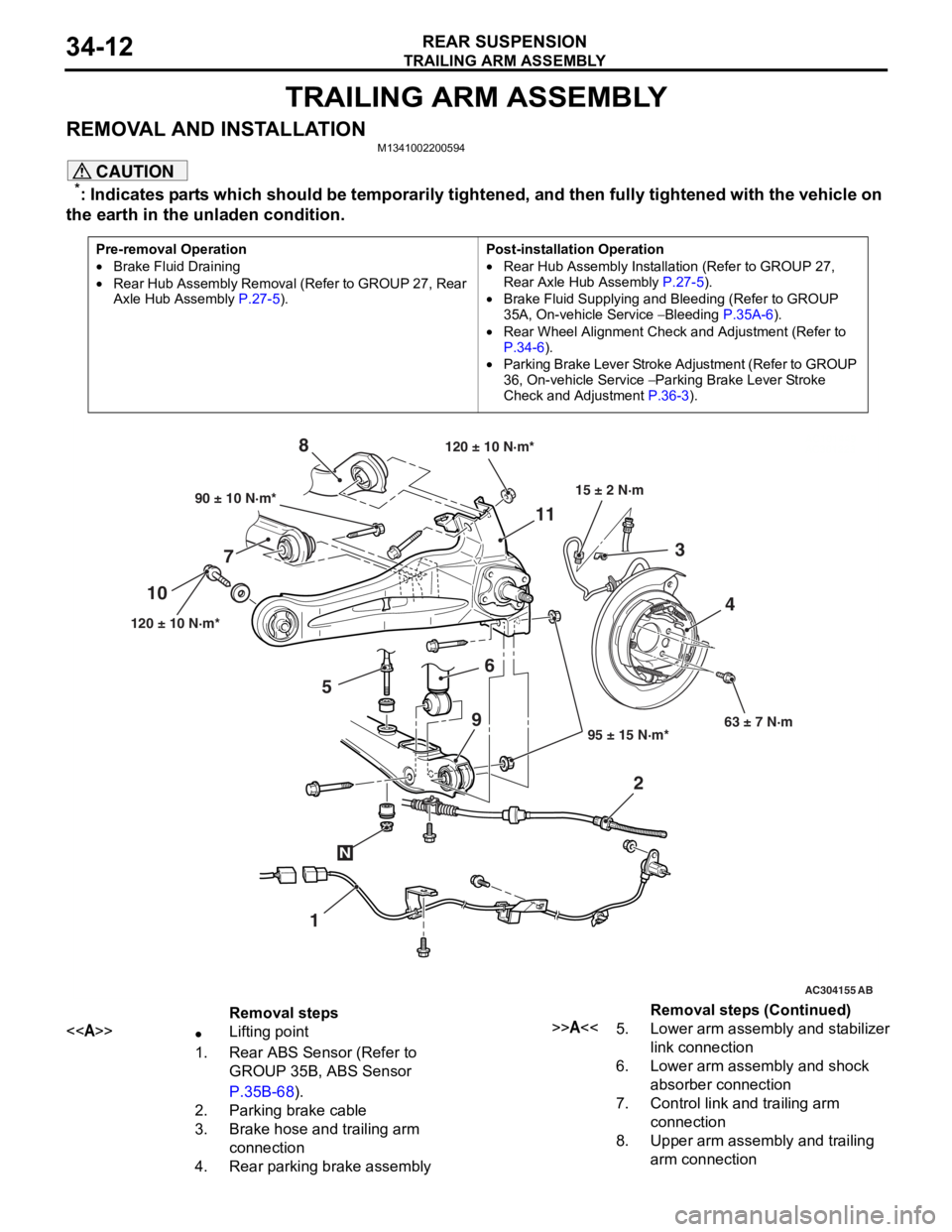
TRAILING ARM ASSEMBLY
REMOVAL AND INSTALLATIONM1341002200594
CAUTION
*: Indicates parts which should be temporarily tightened, and then fully tightened with the vehicle on
the earth in the unladen condition.
Pre-removal Operation
•Brake Fluid Draining
•Rear Hub Assembly Removal (Refer to GROUP 27, Rear
Axle Hub Assembly P.27-5).
Post-installation Operation
•Rear Hub Assembly Installation (Refer to GROUP 27,
Rear Axle Hub Assembly
P.27-5).
•Brake Fluid Supplying and Bleeding (Refer to GROUP
35A, On-vehicle Service
− Bleeding P.35A-6).
•Rear Wheel Alignment Check and Adjustment (Refer to
P.34-6).
•Parking Brake Lever Stroke Ad justment (Refer to GROUP
36, On-vehicle Service
− Parking Brake Lever Stroke
Check and Adjustment
P.36-3).
AC101449
AC301223
AC304155 AB
90 ± 10 N·m*
120 ± 10 N·m* 95 ± 15 N·m*63 ± 7 N·m
6
7 8
1
10
11
23
4
120 ± 10 N·m*
15 ± 2 N·m
N
9
5
Removal steps
<>•Lifting point
1.Rear ABS Sensor (Refer to
GROUP 35B, ABS Sensor
P.35B-68).
2.Parking brake cable
3.Brake hose and trailing arm
connection
4.Rear parking brake assembly
>>A<<5.Lower arm assembly and stabilizer
link connection
6.Lower arm assembly and shock
absorber connection
7.Control link and trailing arm
connection
8.Upper arm assembly and trailing
arm connection
Removal steps (Continued)
Page 219 of 800
35-1
GROUP 35
SERVICE BRAKES
CONTENTS
BASIC BRAKE SYSTEM . . . . . . . . . . . . . . . . . . . . . . . . . . . . . .35A
ANTI-SKID BRAKING SYSTEM (ABS) . . . . . . . . . . . . . . . . . . .35B
Page 221 of 800
36-1
GROUP 36
PARKING BRAKES
CONTENTS
GENERAL INFORMATIO N . . . . . . . .36-2
SERVICE SPECIFICATIONS . . . . . . .36-2
LUBRICANTS . . . . . . . . . . . . . . . . . .36-3
ON-VEHICLE SERVICE . . . . . . . . . . .36-3
PARKING BRAKE LEVER STROKE
CHECK AND ADJUSTMENT . . . . . . . . . . . 36-3
LINING RUNNING-IN . . . . . . . . . . . . . . . . . 36-3
PARKING BRAKE SWITCH CHECK . . . . . 36-4
PARKING BRAKE LEVER . . . . . . . . .36-5
REMOVAL AND INSTALLATION . . . . . . . . 36-5
PARKING BRAKE CABLE . . . . . . . . .36-6
REMOVAL AND INSTALLATION . . . . . . . . 36-6
PARKING BRAKE LINING AND
DRUM . . . . . . . . . . . . . . . . . . . . . . . . .36-7
REMOVAL AND INSTALLATION . . . . . . . . 36-7
INSPECTION. . . . . . . . . . . . . . . . . . . . . . . . 36-9
Page 222 of 800
GENERAL INFORMATION
PARKING BRAKES36-2
GENERAL INFORMATION
M1361000100496
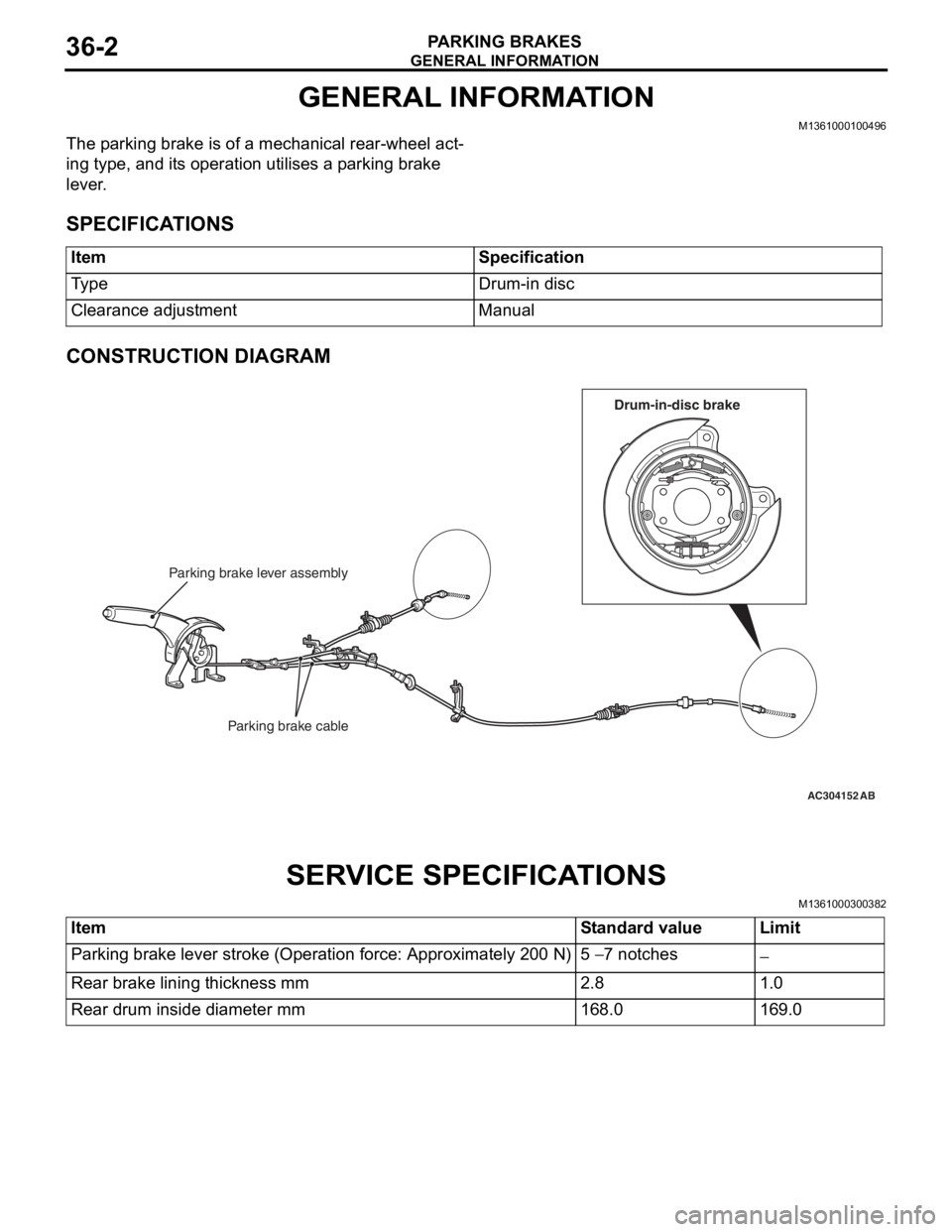
The parking brake is of a mechanical rear-wheel act-
ing type, and its operation utilises a parking brake
lever.
SPECIFICATIONS
ItemSpecification
Ty p eDrum-in disc
Clearance adjustmentManual
CONSTRUCTION DIAGRAM
AC211553
AC104333
AC304152
Parking brake lever assembly
Parking brake cable
AB
Drum-in-disc brake
SERV ICE SPECI F ICA T IONS
M13610003 0038 2
ItemStandard valueLimit
Parking brake lever stroke (Operation force: Approximately 200 N)5 − 7 notches−
Rear brake lining thickness mm2.81.0
Rear drum inside diameter mm168.0169.0
Page 223 of 800
LUBRICANTS
PARKING BRAKES36-3
LUBRICANTS
M1361000400293
ItemSpecified lubricant
Rear brake shoe and backing plate contact surfaceBrake grease SAE J310, NLGI No.1
Rear brake shoe assembly
Rear brake shoe slack adjuster
ON-VEHIC LE SER VI CE
PARKING BRAKE LE VER STROKE
CHECK AND ADJUSTMENT
M13610009 0033 9
1.Pull the p a rkin g brake le ver wit h a force of
ap proxima t ely 200 N an d co unt the number of
no tche s.
St andard va lue: 5 − 7 notches
2.If the p a rking b r ake leve r stro ke is no t the
st a ndard valu e, adjust as de scribed below .
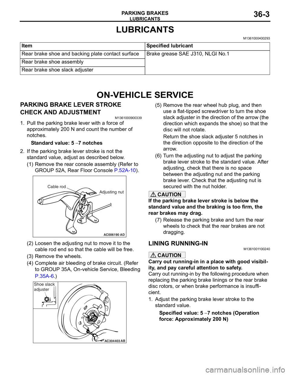
(1)R emove the rear console a sse mbly (Refer to
GROUP 5 2 A, Rear Floor Console
P.52A-10).
AC006190
Cable rod
Adjusting nut
AD
(2)Loosen th e adjusting nu t to move it to th e
cab l e rod end so tha t the cable will be fre e .
(3)R emove the wheels.
(4)C omplete a i r bleedin g of b r ake circuit. (Re f er
to GROUP 35A, On-ve h icle Service, Blee ding
P.35A-6.)
AC304403AB
Shoe slack
adjuster
(5
) R emove the rear whee l hub plug , and then
use a flat-tipped screwdriver to turn the shoe
slack ad juster in the direction of the arrow (the
dire ctio n which exp a nds the shoe) so that the
disc will no t rot a te.
Return the sh oe slack adjust e r 5 not ches in
the d
i rection opposite t o the d i rection of the
arrow
.
(6) T urn th e adjusting nut to adjust the p a rking
brake le ver stroke to the st anda rd value. Af ter
adjusting, check that there is n o sp ace
between the a d justing nut an d the p a rking
brake le ver . Che ck that th e adjusting nut is
secured with the nut ho lder .
CAUTION
If the parking brake lever stroke is below the
standard value and the braking is too firm, the
rear brakes may drag.
(7) Release the parking brake and turn the rear wheels to check that t he rear brakes are not
dragging.
LINING RUNNING-INM1361001100240
CAUTION
Carry out running-in in a place with good visibil-
ity, and pay careful attention to safety.
Carry out running-in by the following procedure when
replacing the parking brake linings or the rear brake
disc rotors, or when brake performance is insuffi
-
cient.
1. Adjust the parking brake lever stroke to the standard value.
Specified value: 5 − 7 notches (Operation
force: Approximately 200 N)
Page 224 of 800
AC212035AC
Spring balance
Approximately
40 mm Pull
ON-V
EHICLE SER VICE
PA R K ING B RAKES36-4
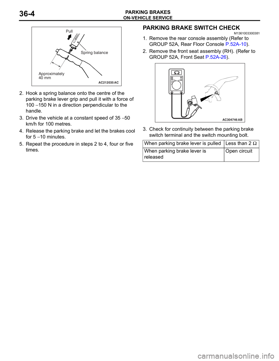
2.Hook a spring bala n ce onto th e ce ntre of the
p a rking brake lever grip and p u ll it with a force of
10 0
− 150 N in a directio n perpe ndicula r to the
ha
ndle .
3. Drive the veh i cle at a const ant speed o f 35 − 50
km/h
for 100
metre
s
.
4. Release the p a rking brake an d let th e bra k es cool
fo r 5
− 10 minutes.
5.Repe at the proce dure in ste p s 2 to 4, four or five
times.
PARKING BRAKE SW ITCH CHECK
M13610033 0038 1
1.Remove the rea r con s ole assembly (Re f er to
GROUP 52A, Rea r Floo r Co nsole
P.52A-10).
2.Remove the fro n t se at assembly (RH). (Re f er to
GROUP 52A, Fr ont Seat
P.5 2 A - 26).
AC304746AB
3.Check f o r co ntinu i ty between t he p a rking bra k e
switch terminal and th e swit ch mounting bo lt.
When parking brake lever is pulledLess than 2 Ω
When parking brake lever is
releasedOpen circuit
Page 225 of 800
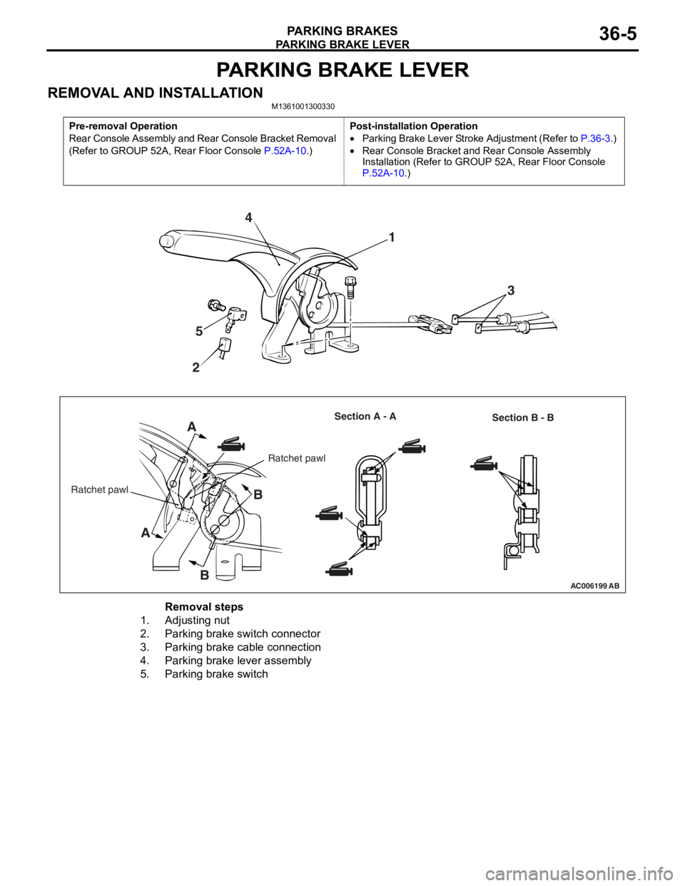
PARKING BRAKE LEVER
PARKING BRAKES36-5
PARKING BRAKE LEVER
REMOVAL AND INSTALLATIONM1361001300330
Pre-removal Operation
Rear Console Assembly and Rear Console Bracket Removal
(Refer to GROUP 52A, Rear Floor Console
P.52A-10.)
Post-installation Operation
•Parking Brake Lever Stroke Adjustment (Refer to P.36-3.)
•Rear Console Bracket and Rear Console Assembly
Installation (Refer to GROUP 52A, Rear Floor Console
P.52A-10.)
AC006199AB
4
5
2 1
3
A
A B
B
Ratchet pawl Section A - A
Section B - B
Ratchet pawl
Removal steps
1.Adjusting nut
2.Parking brake switch connector
3.Parking brake cable connection
4.Parking brake lever assembly
5.Parking brake switch
Page 226 of 800
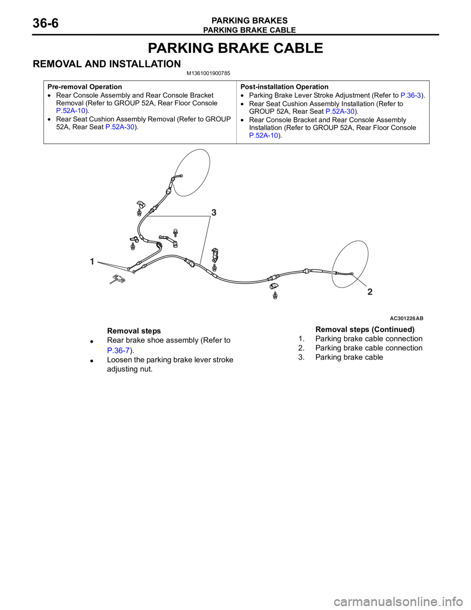
PARKING BRAKE CABLE
PARKING BRAKES36-6
PARKING BRAKE CABLE
REMOVAL AND INSTALLATIONM1361001900785
Pre-removal Operation
•Rear Console Assembly and Rear Console Bracket
Removal (Refer to GROUP 52A, Rear Floor Console
P.52A-10).
•Rear Seat Cushion Assembly Removal (Refer to GROUP
52A, Rear Seat
P.52A-30).
Post-installation Operation
•Parking Brake Lever Stroke Adjustment (Refer to P.36-3).
•Rear Seat Cushion Assembly Installation (Refer to
GROUP 52A, Rear Seat P.52A-30).
•Rear Console Bracket and Rear Console Assembly
Installation (Refer to GROUP 52A, Rear Floor Console
P.52A-10).
AC301226
1
AB
2
3
Removal steps
•Rear brake shoe assembly (Refer to
P.36-7).
•Loosen the parking brake lever stroke
adjusting nut.
1.Parking brake cable connection
2.Parking brake cable connection
3.Parking brake cable
Removal steps (Continued)