cap MITSUBISHI LANCER 2006 User Guide
[x] Cancel search | Manufacturer: MITSUBISHI, Model Year: 2006, Model line: LANCER, Model: MITSUBISHI LANCER 2006Pages: 800, PDF Size: 45.03 MB
Page 115 of 800
EMISSION CONTROL
ENGINE AND EMISSION CONTROL17-9
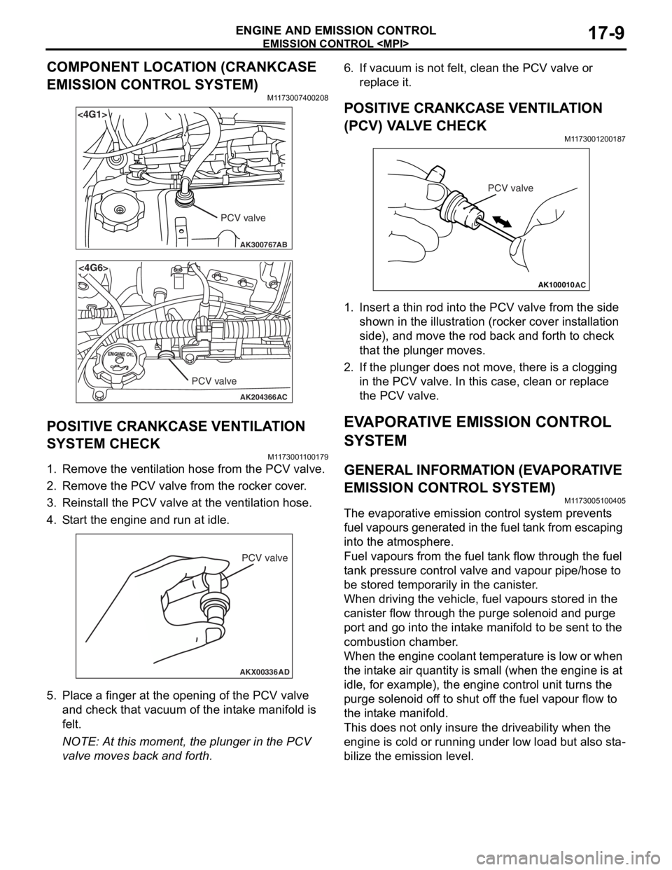
COMPONENT LOCATION (CRANKCASE
EMISSION CONTROL SYSTEM)
M1173007400208
AK300767
<4G1>
AB
PCV valve
AK204366
<4G6>
AC
PCV valve
POSITIVE CRANKCASE VENTILATION
SYSTEM CHECK
M11 7300 1 1 0017 9
1.Remove the ventilatio n hose from the PCV valve.
2.Remove the PCV valve from t he rocker cove r .
3.Reinst all the PCV valve at the ven t ila tion h o se.
4.S t art the engin e and run at idle .
AKX00336
PCV valve
AD
5.Pla c e a fing er at the open ing o f the PCV va lve
an d ch eck that vacu um o f the int a ke manifold is
fe lt.
NOTE: At this mo men t, the p l unge r in t he PCV
valve mo ves back an d forth.
6.If vacuum is not felt, clean t he PCV valve o r
re place it.
POSITIVE CRANKCASE VENTILA TION
(
P CV) V A L VE CHECK
M1173 0012 0018 7
AK100010
PCV valve
AC
1.In sert a thin rod in to the PCV valve from the side
shown in the illu strat i on (ro cke r cover in st allation
side) , and move the ro d back an d forth to ch eck
th at the plung er mo ves.
2.If the plunger does not move , there is a clo ggin g
in the PCV valve. In th is case, clean o r repla c e
th e PCV valve.
EVAPORA T IVE EMISSION CONTROL
SYSTEM
GENERAL INFORMA T ION (EV A PORA TIVE
EMISSION CONTROL SYSTEM)
M1173 0051 0040 5
The evaporat ive emission contro l syste m pre v ent s
f
uel vapours generat ed in t he fuel t ank from escaping
into t
he atmosp here.
Fuel vapours fro m the fuel t a n k flow throug h the f uel
t
a n k pre ssu re co ntrol valve an d vap our pipe/ho se to
be st
ored te mpora r ily in t he ca nister .
When dr iving the veh i cle, fue l va pours stor ed in the
canister
flow thro ugh th e purge solenoid and purge
port an
d go into the int a ke ma nifold to b e sen t to th e
combust
i on chamber .
When the eng ine co ola n t te mp eratu r e is low o r when
the int
a ke air q uantity is small (wh en the engine is at
idle
, for example), t he eng ine contro l unit turns the
purge sole
noid of f to shu t of f the fue l va pour flow to
the in
t a ke manif o ld.
This does not on ly insure the driveability when t he
engin
e is cold or runn ing und er low load b u t also st a
-
bilize the emissio n level.
Page 158 of 800
GENERAL INFORMATION
REAR AXLE27-2
GENERAL INFORMATION
M1271000100304
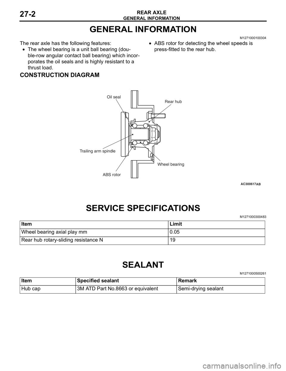
The rear axle has the following features:
•The wheel bearing is a unit ball bearing (dou-
ble-row angular contact ball bearing) which incor-
porates the oil seals and is highly resistant to a
thrust load.
•ABS rotor for detecting the wheel speeds is
press-fitted to the rear hub.
CONSTRUCTION DIAGRAM
AC300617AB
Rear hub
Oil seal
Wheel bearing
ABS rotor
Trailing arm spindle
SER
V ICE SPECI F ICA T IONS
M12710003 0048 3
ItemLimit
Wheel bearing axial play mm0.05
Rear hub rotary-sliding resistance N19
SEALANT
M12710005 0026 1
ItemSpecified sealantRemark
Hub cap3M ATD Part No.8663 or equivalentSemi-drying sealant
Page 159 of 800
SPECIAL TOOLS
REAR AXLE27-3
SPECIAL TOOLS
M1271000600495
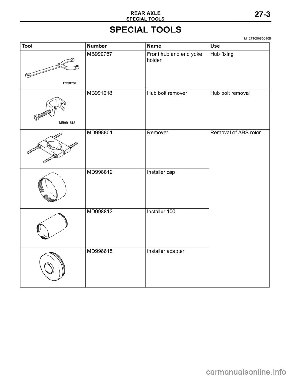
ToolNumberNameUse
B990767
MB990767Front hu b and end yoke
holde
rHub fixin g
MB991618
MB991618Hub bolt remo verHub bolt remova l
MD998801Remov e rRemoval of ABS rotor
MD998812Installer cap
MD9988 13Installer 100
MD9988 15Installer ada pter
Page 161 of 800
REAR AXLE HUB ASSEMBLY
REAR AXLE27-5
REAR AXLE HUB ASSEMBLY
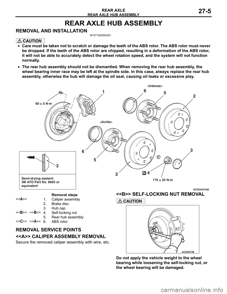
REMOVAL AND INSTALLATIONM1271002000381
CAUTION
•Care must be taken not to scratch or damage the teeth of the ABS rotor. The ABS rotor must never
be dropped. If the teeth of the ABS rotor are chipped, resulting in a deformation of the ABS rotor,
it will not be able to accurately detect the wheel rotation speed, and the system will not function
normally.
•
AC504437
Semi-drying sealant:
3M ATD Part No. 8663 or
equivalent
2
3
5
6
4
N
175 ± 25 N·m
3
AB
1
60 ± 5 N·m
2
56
Removal steps
<>1.Caliper assembly
2.Brake disc
3.Hub cap
<>>>B<<4.Self-locking nut
5.Rear hub assembly
<
The rear hub assembly should not be dismantled. When removing the rear hub assembly, the
wheel bearing inner race may be left at the spindle side. In this case, always replace the rear hub
assembly, otherwise the hub will damage the oil seal, causing oil leaks or excessive play.
REMOVAL SERVICE POINTS
<> CALIPER ASSEMBLY REMOVAL
Secure the removed caliper assembly with wire, etc.
<> SELF-LOCKING NUT REMOVAL
AC303738
CAUTION
Do not apply the vehicle weight to the wheel
bearing while loosening the self-locking nut, or
the wheel bearing will be damaged.
Page 162 of 800
REAR AXLE HUB ASSEMBLY
REAR AXLE27-6
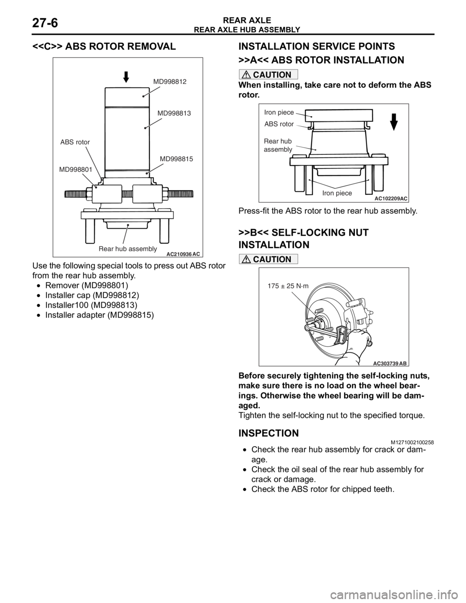
<
AC210936AC
MD998815
MD998801 MD998813
MD998812
Rear hub assembly
ABS rotor
Use
the fo llowing specia l to ols t o press o u t ABS rot o r
from th
e rear h ub assembly .
•Remover (MD99880 1)
•Insta lle r cap (MD9988 12)
•Insta lle r100 (MD9 98813 )
•Insta lle r adapte r (MD998 815)
INSTALLA T ION SER VICE POINTS
>>A<< ABS ROTO R INST ALLA TION
CAUTION
When installing, take care not to deform the ABS
rotor.
AC102209
Iron piece
ABS rotor
Rear hub
assembly
Iron piece
AC
Press-fit the ABS rotor to the rear hub assembly.
>>B<< SELF-LOCKING NUT
INSTALLATION
AC303739
175 ± 25 N·m
AB
CAUTION
Before securely tightening the self-locking nuts,
make sure there is no load on the wheel bear
-
ings. Otherwise the wheel bearing will be dam-
aged.
Tighten the self-locking nut to the specified torque.
INSPECTIONM1271002100258
•Check the rear hub assembly for crack or dam-
age.
•Check the oil seal of the rear hub assembly for
crack or damage.
•Check the ABS rotor for chipped teeth.
Page 246 of 800
ON-VEHICLE SERVICE
POWER STEERING37-16
WARNING
•If the vehicle continues to be driven after
the collision absorbing mechanism has
operated, the steering column shaft may
be damaged while it is in use.
•If there is a slack in the one-way capsule,
do not attempt to repa ir it but replace the
steering column shaft assembly.
Inspection Procedure
1. Remove the lower and upper column covers.
CAUTION
Do not release the tilt lever until the steering col-
umn has been installed to complete this inspec-
tion procedure.
2. Ensure that the tilt lever is in the lock position.
NOTE: If not, place the tilt lever in the lock posi-
tion.
AC304673AC304673
Steering
column
assembly
AB
Steering
column
mounting
bolt
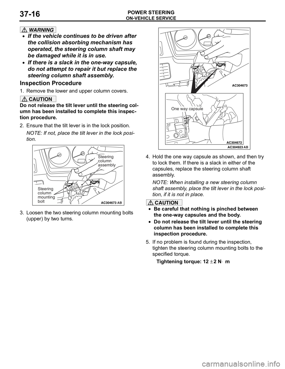
3. Loosen the two steering column mounting bolts
(upper) by two turns.
AC304672
AC304673AC304673
AC304923 AB
One way capsule
4. Hold the one way capsule as shown, and then try
to lock them. If there is a slack in either of the
capsules, replace the steering column shaft
assembly.
NOTE: When installing a new steering column
shaft assembly, place the tilt lever in the lock posi
-
tion, if it is not in place.
CAUTION
•Be careful that nothing is pinched between
the one-way capsules and the body.
•Do not release the tilt lever until the steering
column has been installed to complete this
inspection procedure.
5. If no problem is found during the inspection, tighten the steering column mounting bolts to the
specified torque.
Tightening torque: 12 ± 2 N⋅m
Page 303 of 800
DOOR
BODY42-31
DOOR ASSEMBLY
REMOVAL AND INSTALLATION
M1423002200283
Post-installation Operation
•Door Fit Adjustment (Refer to P.42-27.)
Y0655AUAC006125
ACX00503
Y0652AU
5, 6
AB
1
2 3
4
5
6 7
8
9 10
1
23 4
5
6 7
8
9 10
11.5 ± 0.5 N·m
1.5 ± 0.5 N·m
11 ± 2 N·m 11 ± 2 N·m
11 ± 2 N·m
11 ± 2 N·m
21 ± 4 N·m 27 ± 5 N·m
21 ± 4 N·m
27 ± 5 N·m
21 ± 4 N·m
27 ± 5 N·m
21 ± 4 N·m
27 ± 5 N·m
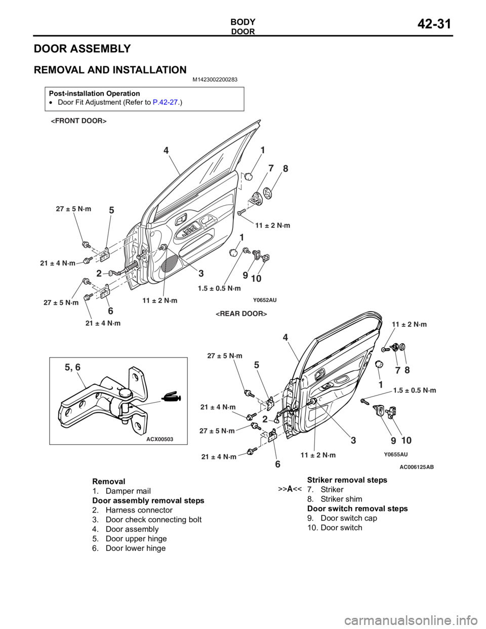
Removal
1.Damper mail
Door assembly removal steps
2.Harness connector
3.Door check connecting bolt
4.Door assembly
5.Door upper hinge
6.Door lower hinge
Striker removal steps
>>A<<7.Striker
8.Striker shim
Door switch removal steps
9.Door switch cap
10.Door switch
Page 357 of 800
REAR SPOILER
EXTERIOR51-25
REAR SPOILER
REMOVAL AND INSTALLATIONM1511006100136
AC303713
2
3
4
2 1
AB
1
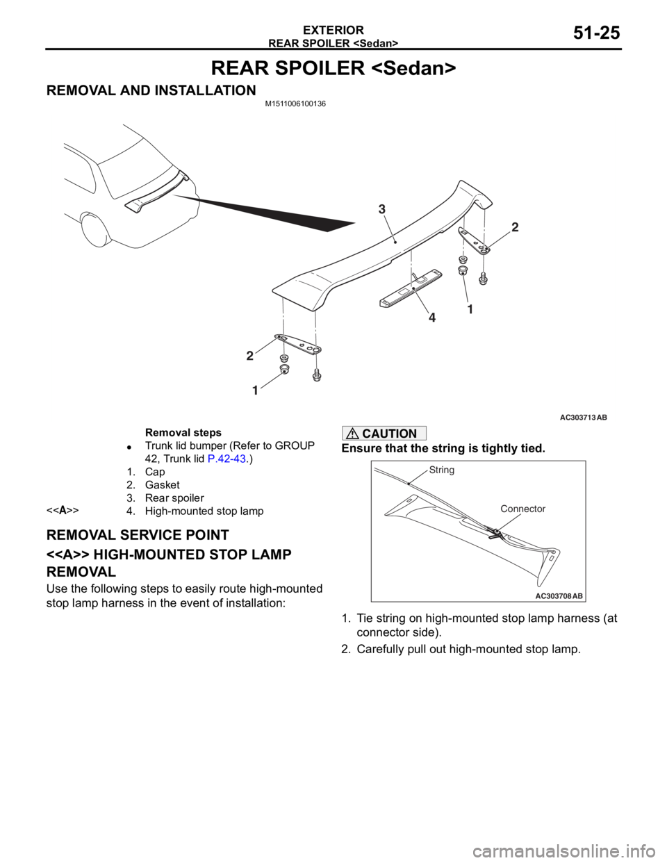
Removal steps
•Trunk lid bumper (Refer to GROUP
42, Trunk lid
P.42-43.)
1.Cap
2.Gasket
3.Rear spoiler
<>4.High-mounted stop lamp
REMOV A L SER V ICE POINT
< > HIGH-MOUNTED ST OP LAMP
REMOV
A L
Use the following step s to ea sily ro ute high-mounted
stop
lamp harne ss in the eve n t of inst allation:
CAUTION
Ensure that the string is tightly tied.
AC303708
Connector
String
AB
1. Tie string on high-mounted stop lamp harness (at
connector side).
2. Carefully pull out high-mounted stop lamp.
Page 430 of 800
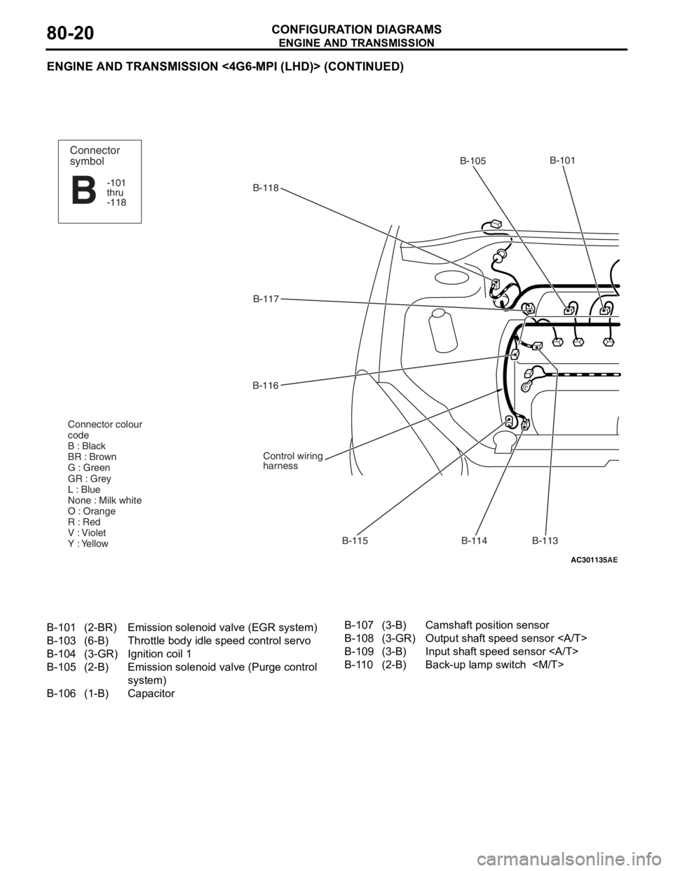
ENGINE AND TRANSMISSION
CONFIGURATION DIAGRAMS80-20
ENGINE AND TRANSMISSION <4G6-MPI (LHD)> (CONTINUED)
AC301135AE
B-118B-101
B-114
B-115
B-116
B-117
Control wiring
harness
Connector colour
code
B : Black
BR : Brown
G : Green
GR : Grey
L : Blue
None : Milk white
O : Orange
R : Red
V : Violet
Y : Yellow
B-113
B-105Connector
symbol
-101
thru
-118
B
B-101(2-BR)Emission solenoid
valve (EGR system)
B-103(6-B)Throttle body idle speed control servo
B-104(3-GR)Ignition coil 1
B-105(2-B)Emission solenoid va lve (Purge control
system)
B-106(1-B)Capacitor
B-107(3-B)Camshaft position sensor
B-108(3-GR)Output shaft speed sensor
B-109(3-B)Input shaft speed sensor
B-110(2-B)Back-up lamp switch
Page 434 of 800
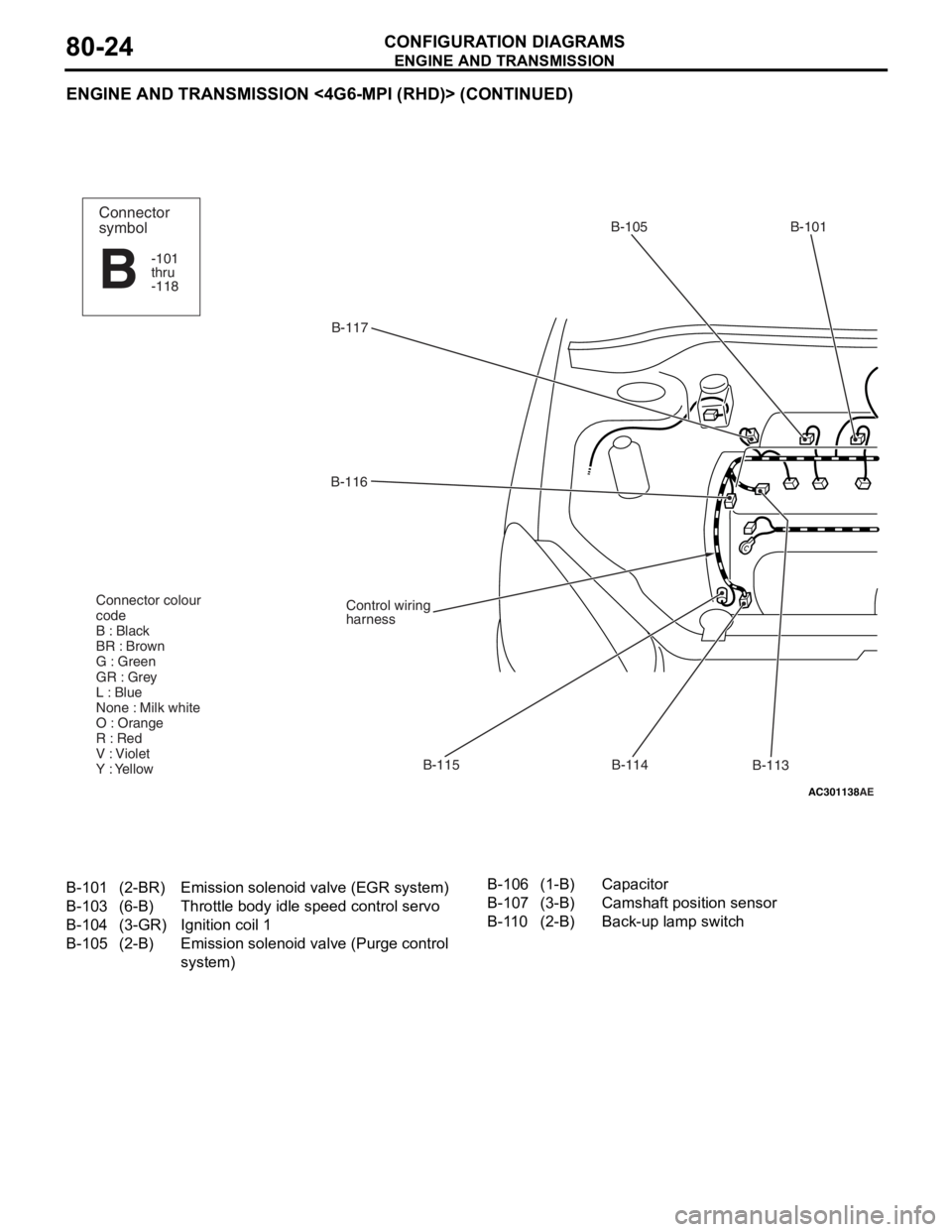
ENGINE AND TRANSMISSION
CONFIGURATION DIAGRAMS80-24
ENGINE AND TRANSMISSION <4G6-MPI (RHD)> (CONTINUED)
AC301138AE
B-117B-105 B-101
B-113
B-114
B-115
B-116
Control wiring
harness
Connector colour
code
B : Black
BR : Brown
G : Green
GR : Grey
L : Blue
None : Milk white
O : Orange
R : Red
V : Violet
Y : Yellow
Connector
symbol
-101
thru
-118
B
B-101(2-BR)Emission solenoid
valve (EGR system)
B-103(6-B)Throttle body idle speed control servo
B-104(3-GR)Ignition coil 1
B-105(2-B)Emission solenoid va lve (Purge control
system)
B-106(1-B)Capacitor
B-107(3-B)Camshaft position sensor
B-110(2-B)Back-up lamp switch