engine coolant MITSUBISHI LANCER 2006 User Guide
[x] Cancel search | Manufacturer: MITSUBISHI, Model Year: 2006, Model line: LANCER, Model: MITSUBISHI LANCER 2006Pages: 800, PDF Size: 45.03 MB
Page 43 of 800
WATER HOSE AND WATER PIPE
ENGINE COOLING14-29
WATER HOSE AND WATER PIPE
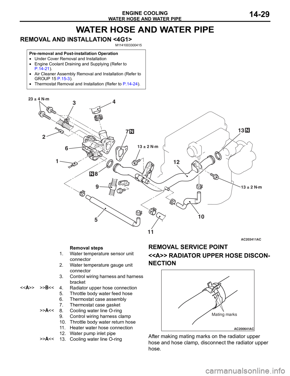
REMOVAL AND INSTALLATION <4G1>M1141003300415
Pre-removal and Post-installation Operation
•Under Cover Removal and Installation
•Engine Coolant Draining and Supplying (Refer to P.14-21).
•Air Cleaner Assembly Removal and Installation (Refer to
GROUP 15 P.15-3).
•Thermostat Removal and Installation (Refer to P.14-24).
AC203411
1
2 3
4
5
6
7
8
10
9
13 ± 2 N·m
23 ± 4 N·m
13 ± 2 N·m
N
N
AC
1112
13
N
Removal steps
1.Water temperature sensor unit
connector
2.Water temperature gauge unit
connector
3.Control wiring harness and harness
bracket
<>>>B<<4.Radiator upper hose connection
5.Throttle body water feed hose
6.Thermostat case assembly
7.Thermostat case gasket
>>A<<8.Cooling water line O-ring
9.Control wiring harness clamp
10.Throttle body water return hose
11 .Heater water hose connection
12.Water pump inlet pipe
>>A<<13.Cooling water line O-ring
REMOV
A L SER VICE POINT
<> RADIAT OR UPPER HOSE DISCON-
NECTION
AC200641AC
Mating marks
After making matin g ma rks on the radia t or upp er
hose
and h o se clamp, disconnect the radia t or upp er
hose
.
Page 44 of 800
WATER HOSE AND WATER PIPE
ENGINE COOLING14-30
INSTALLATION SERVICE POINTS
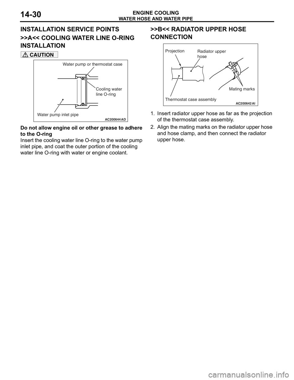
>>A<< COOLING WATER LINE O-RING
INSTALLATION
AC200644 AD
Cooling water
line O-ring
Water pump inlet pipe Water pump or thermostat case
CAUTION
Do not allow engine oil or other grease to adhere
to the O-ring
Insert the cooling water line O-ring to the water pump
inlet pipe, and coat the outer portion of the cooling
water line O-ring with water or engine coolant.
>>B<< RADIATOR UPPER HOSE
CONNECTION
AC200642
Mating marks
Projection
Thermostat case assemblyAI
Radiator upper
hose
1. Insert radiator upper hose as far as the projection
of the thermostat case assembly.
2. Align the mating marks on the radiator upper hose and hose clamp, and then connect the radiator
upper hose.
Page 45 of 800
WATER HOSE AND WATER PIPE
ENGINE COOLING14-31
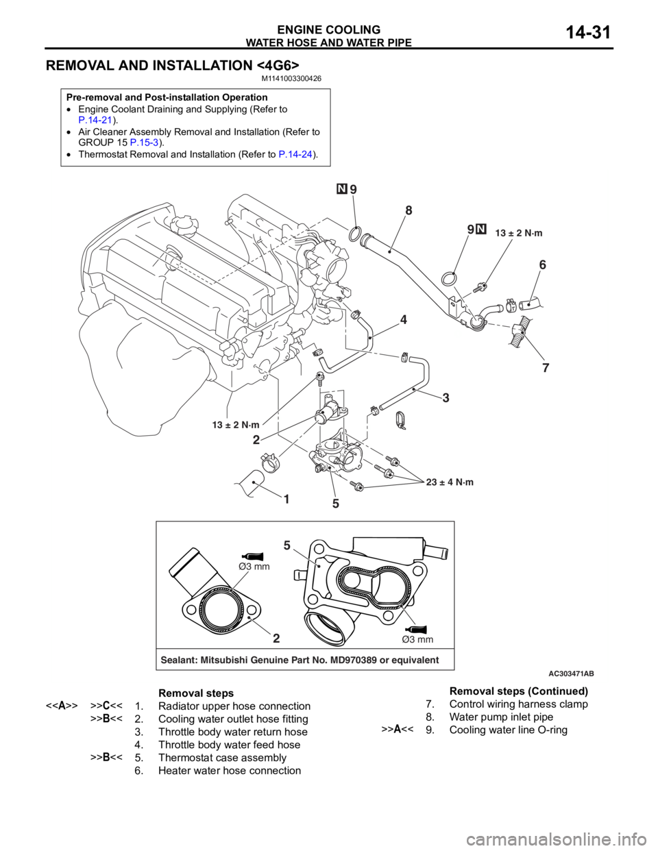
REMOVAL AND INSTALLATION <4G6>
M1141003300426
Pre-removal and Post-installation Operation
•Engine Coolant Draining and Supplying (Refer to P.14-21).
•Air Cleaner Assembly Removal and Installation (Refer to
GROUP 15 P.15-3).
•Thermostat Removal and Installation (Refer to P.14-24).
AC303471
1
2
3
4
5 6
7
8
9
9
13 ± 2 N·m
23 ± 4 N·m
13 ± 2 N·m
N
N
AB
2
Sealant: Mitsubishi Genuine Part No. MD970389 or equivalent
Ø3 mm
Ø3 mm
5
Removal steps
<>>>C<<1.Radiator upper hose connection
>>B<<2.Cooling water outlet hose fitting
3.Throttle body water return hose
4.Throttle body water feed hose
>>B<<5.Thermostat case assembly
6.Heater water hose connection
7.Control wiring harness clamp
8.Water pump inlet pipe
>>A<<9.Cooling water line O-ring
Removal steps (Continued)
Page 47 of 800
RADIATOR
ENGINE COOLING14-33
RADIATOR
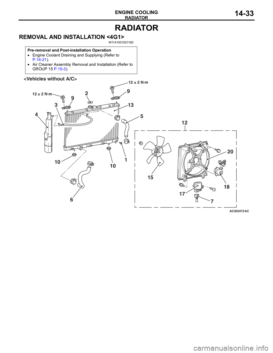
REMOVAL AND INSTALLATION <4G1>M1141001501160
Pre-removal and Post-installation Operation
•Engine Coolant Draining and Supplying (Refer to
P.14-21).
•Air Cleaner Assembly Removal and Installation (Refer to
GROUP 15
P.15-3).
AC303472
18
17
15 20
12
9
13 5
2
9
3
4
1
10
6
10
AC
12 ± 2 N·m
12 ± 2 N·m
7
Page 49 of 800
RADIATOR
ENGINE COOLING14-35
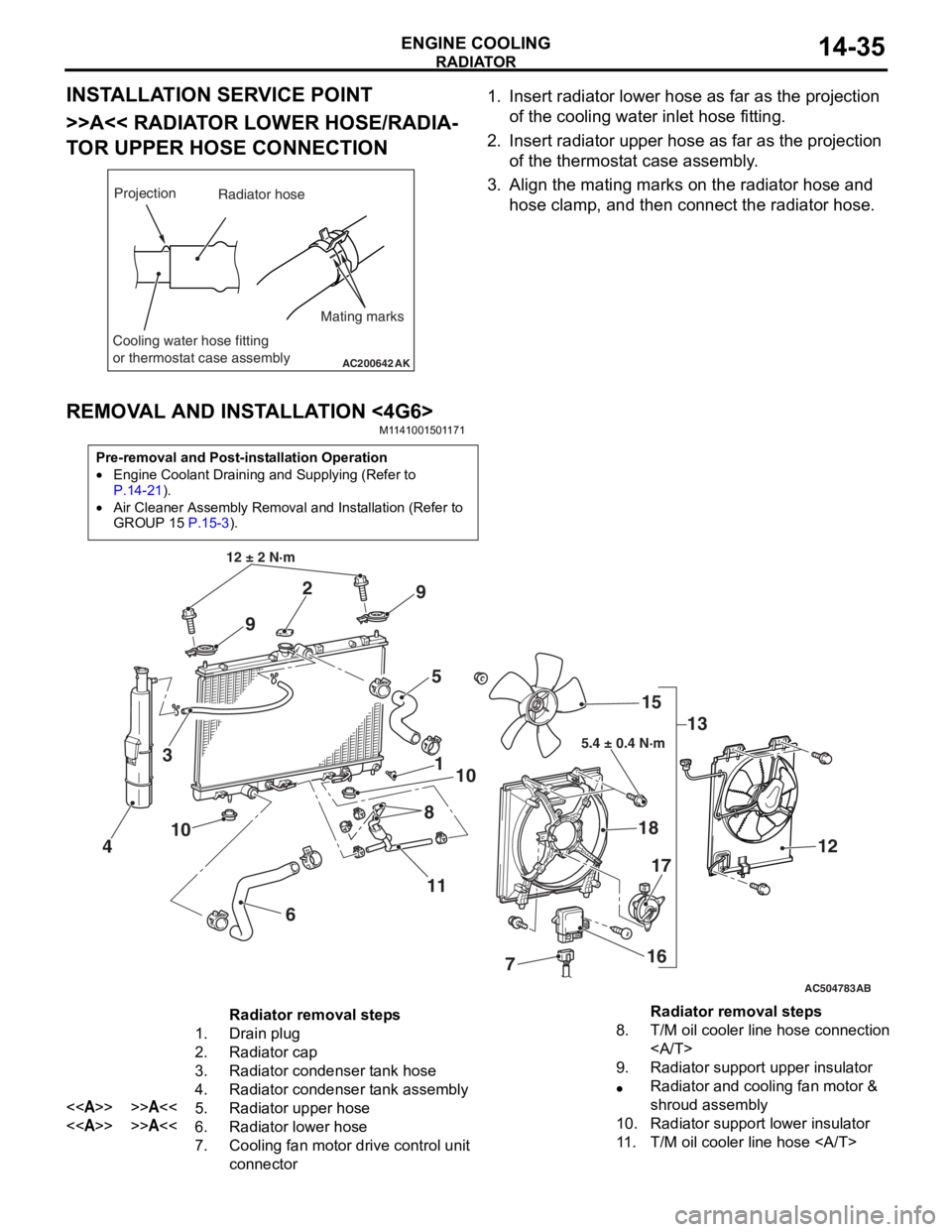
INSTALLATION SERVICE POINT
>>A<< RADIATOR LOWER HOSE/RADIA-
TOR UPPER HOSE CONNECTION
AC200642
Mating marks
Projection
Cooling water hose fitting
or thermostat case assembly
AK
Radiator hose
1.In sert ra diato r lower h o se as fa r as th e projection
o f the cooling wate r inlet hose fit t ing.
2.In sert radia t or up per h o se as far a s t he pro j ection
o f the th ermost at ca se asse mbly .
3.Align th e ma ting marks on the rad i ator hose and
h o se clamp, an d then conn ect the radiator h o se.
REMOVA L AND INST ALLA TION <4G6>
M11 4100 1501 17 1
Pre-removal and Post-installation Operation
•Engine Coolant Draining and Supplying (Refer to
P.14-21).
•Air Cleaner Assembly Removal and Installation (Refer to
GROUP 15
P.15-3).
AC504783
1
12 ± 2 N·m
10
2
3
4
5
6
7
8
9
9
10
11 13
15
18
16
17
12
AB
5.4 ± 0.4 N·m
Radiator removal steps
1.Drain plug
2.Radiator cap
3.Radiator condenser tank hose
4.Radiator condenser tank assembly
<>>>A<<5.Radiator upper hose
<>>>A<<6.Radiator lower hose
7.Cooling fan motor drive control unit
connector
8.T/M oil cooler line hose connection
9.Radiator support upper insulator
•Radiator and cooling fan motor &
shroud assembly
10.Radiator support lower insulator
11 .T/M oil cooler line hose
Radiator removal steps
Page 55 of 800
INLET MANIFOLD
INTAKE AND EXHAUST15-5
INLET MANIFOLD
REMOVAL AND INSTALLATION <4G1>M1151003000749
Pre-removal Operation
•Fuel Line Pressure Reduction (Refer to GROUP 13A -
On-vehicle Service
P.13A-372).
•Engine Coolant Draining (Refer to GROUP 14 - On-vehi-
cle Service P.14-21).
•Strut Tower Bar Removal (Refer to GROUP 42 P.42-9).
•Throttle Body Assembly Re moval (Refer to GROUP 13A
P.13A-383).
•Fuel Delivery Pipe and Fuel Injector Assembly Removal
(Refer to GROUP 13A
P.13A-381).
Post-installation Operation
•Fuel Delivery Pipe and Fuel Injector Assembly Installation
(Refer to GROUP 13A
P.13A-381).
•Throttle Body Assembly Inst allation (Refer to GROUP
13A
P.13A-383).
•Strut Tower Bar Installati on (Refer to GROUP 42 P.42-9).
•Engine Coolant Supplying (Refer to GROUP 14 - On-vehi-
cle Service P.14-21).
•Accelerator Cable Adjustment (Refer to GROUP 17 -
On-vehicle Service
P.17-2).
•Fuel Leak Check
AC303642AB
15
36
5
4 12
10
7
1
2
11
9 13
14
21 ± 4 N·m
9.0 ± 1.0 N·m
9.0 ± 1.0 N·m
18 ± 2 N·m
18 ± 2 N·m 18 ± 2 N·m
5.0 ± 1.0 N·m
31 ± 3 N·m
49 ± 9 N·m
N
N
N
8
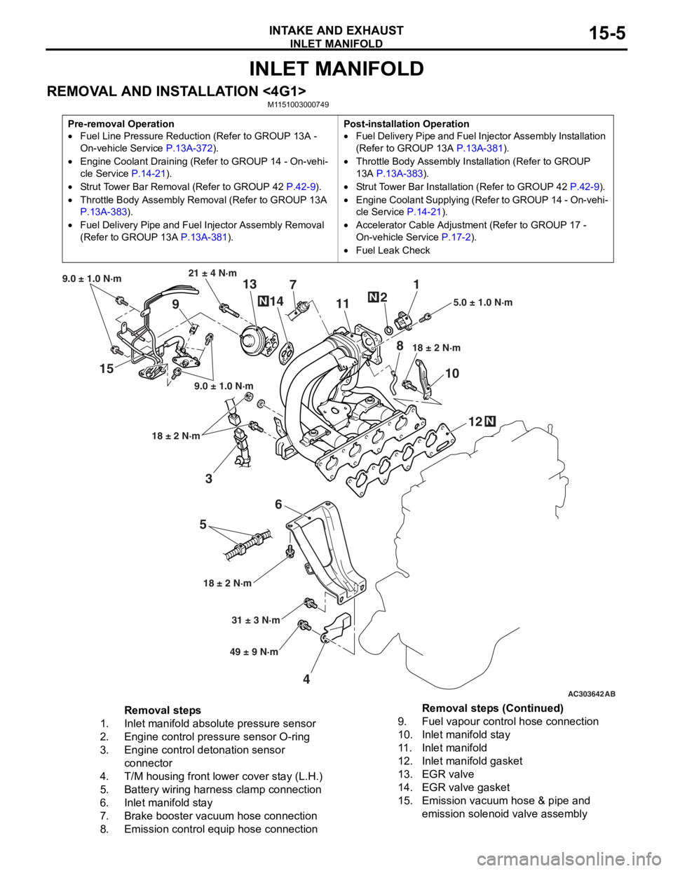
Removal steps
1.Inlet manifold absolute pressure sensor
2.Engine control pressure sensor O-ring
3.Engine control detonation sensor
connector
4.T/M housing front lower cover stay (L.H.)
5.Battery wiring harness clamp connection
6.Inlet manifold stay
7.Brake booster vacuum hose connection
8.Emission control equip hose connection
9.Fuel vapour control hose connection
10.Inlet manifold stay
11 .Inlet manifold
12.Inlet manifold gasket
13.EGR valve
14.EGR valve gasket
15.Emission vacuum hose & pipe and
emission solenoid valve assembly
Removal steps (Continued)
Page 56 of 800
INLET MANIFOLD
INTAKE AND EXHAUST15-6
REMOVAL AND INSTALLATION <4G6>
M1151003001236
Pre-removal Operation
•Fuel Line Pressure Reduction (Refer to GROUP 13A -
On-vehicle Service P.13B-325).
•Engine Coolant Draining (Refer to GROUP 14 - On-vehi-cle Service P.14-21).
•Strut Tower Bar Removal (Refer to GROUP 42 P.42-9).
•Throttle Body Assembly Re moval (Refer to GROUP 13B
P.13B-335).
•Fuel Delivery Pipe and Fuel Injector Assembly Removal
(Refer to GROUP 13B
P.13B-333).
Post-installation Operation
•Fuel Delivery Pipe and Fuel Injector Assembly Installation
(Refer to GROUP 13B P.13B-333).
•Throttle Body Assembly Inst allation (Refer to GROUP
13B P.13B-335).
•Strut Tower Bar Installati on (Refer to GROUP 42 P.42-9).
•Engine Coolant Supplying (Refer to GROUP 14 - On-vehi-
cle Service P.14-21).
•Accelerator Cable Adjustment (Refer to GROUP 17 -
On-vehicle Service
P.17-2).
•Fuel Leak Check
AC303657
9.0 ± 1.0 N·m11 ± 1 N·m
20 ± 2 N·m 31 ± 3 N·m
36 ± 6 N·m
20 ± 2 N·m
20 ± 2 N·m
36 ± 6 N·m
20 ± 2 N·m
11
9
10
2
12
N14
13N
AB
5.0 ± 1.0 N·m
3
1
11 ± 1 N·m
4
N
13 ± 1 N·m
5
6
(Engine oil)
7
8
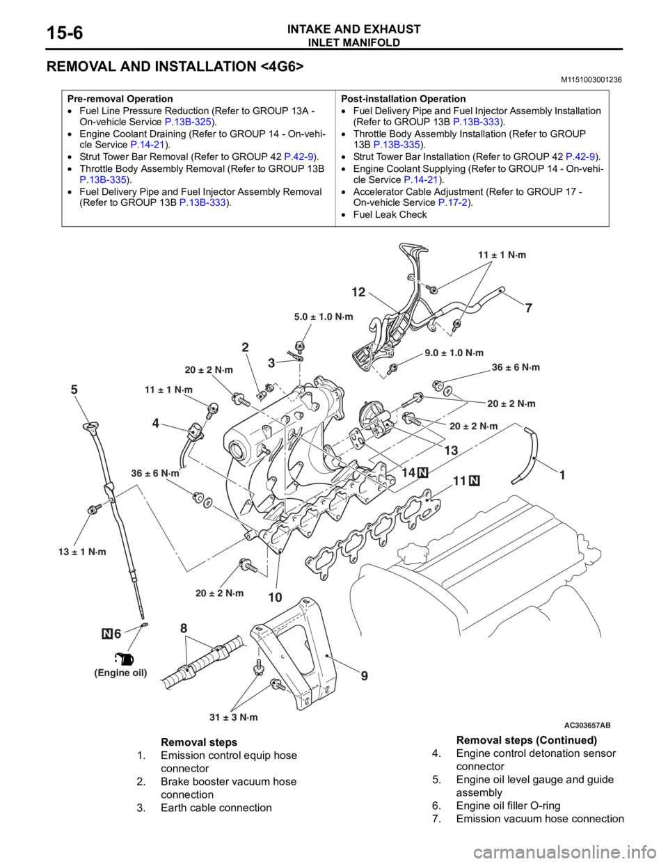
Removal steps
1.Emission control equip hose
connector
2.Brake booster vacuum hose
connection
3.Earth cable connection
4.Engine control detonation sensor
connector
5.Engine oil level gauge and guide
assembly
6.Engine oil filler O-ring
7.Emission vacuum hose connection
Removal steps (Continued)
Page 92 of 800
IGNITION SYSTEM
ENGINE ELECTRICAL16-30
IGNITION SYSTEM
GENERAL INFORMATIONM1163000100294
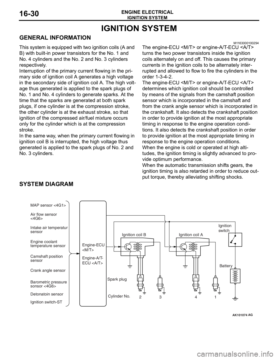
This system is equipped with two ignition coils (A and
B) with built-in power transistors for the No. 1 and
No. 4 cylinders and the No. 2 and No. 3 cylinders
respectively.
Interruption of the primary current flowing in the pri-
mary side of ignition coil A generates a high voltage
in the secondary side of ignition coil A. The high volt
-
age thus generated is applied to the spark plugs of
No. 1 and No. 4 cylinders to generate sparks. At the
time that the sparks are generated at both spark
plugs, if one cylinder is at the compression stroke,
the other cylinder is at the exhaust stroke, so that
ignition of the compressed air/fuel mixture occurs
only for the cylinder which is at the compression
stroke.
In the same way, when the primary current flowing in
ignition coil B is interrupted, the high voltage thus
generated is applied to the spark plugs of No. 2 and
No. 3 cylinders.
The engine-ECU
turns the two power transistors inside the ignition
coils alternately on and off. This causes the primary
currents in the ignition coils to be alternately inter
-
rupted and allowed to flow to fire the cylinders in the
order 1-3-4-2.
The engine-ECU
determines which ignition coil should be controlled
by means of the signals from the camshaft position
sensor which is incorporated in the camshaft and
from the crank angle sensor which is incorporated in
the crankshaft. It also detects the crankshaft position
in order to provide ignition at the most appropriate
timing in response to the engine operation condi
-
tions. It also detects the crankshaft position in order
to provide ignition at the most appropriate timing in
response to the engine operation conditions.
When the engine is cold or operated at high alti-
tudes, the ignition timing is slightly advanced to pro-
vide optimum performance.
When the automatic transmission shifts gears, the
ignition timing is also retarded in order to reduce out
-
put torque, thereby alleviating shifting shocks.
SYSTEM DIAGRAM
AK101074
Air flow sensor
<4G6> MAP sensor <4G1>
Intake air temperatur
sensor
Engine coolant
temperature sensor
Camshaft position
sensor
Crank angle sensor
Barometric pressure
sonsor <4G6>
Detonatoin sensor
Ignition switch-ST Engine-A/T-
ECU Engine-ECU
Ignition coil B
Cylinder No. 23 4
AG
1
Spark plug Ignition coil A
Ignition
switch
Battery
Page 116 of 800
EMISSION CONTROL
ENGINE AND EMISSION CONTROL17-10
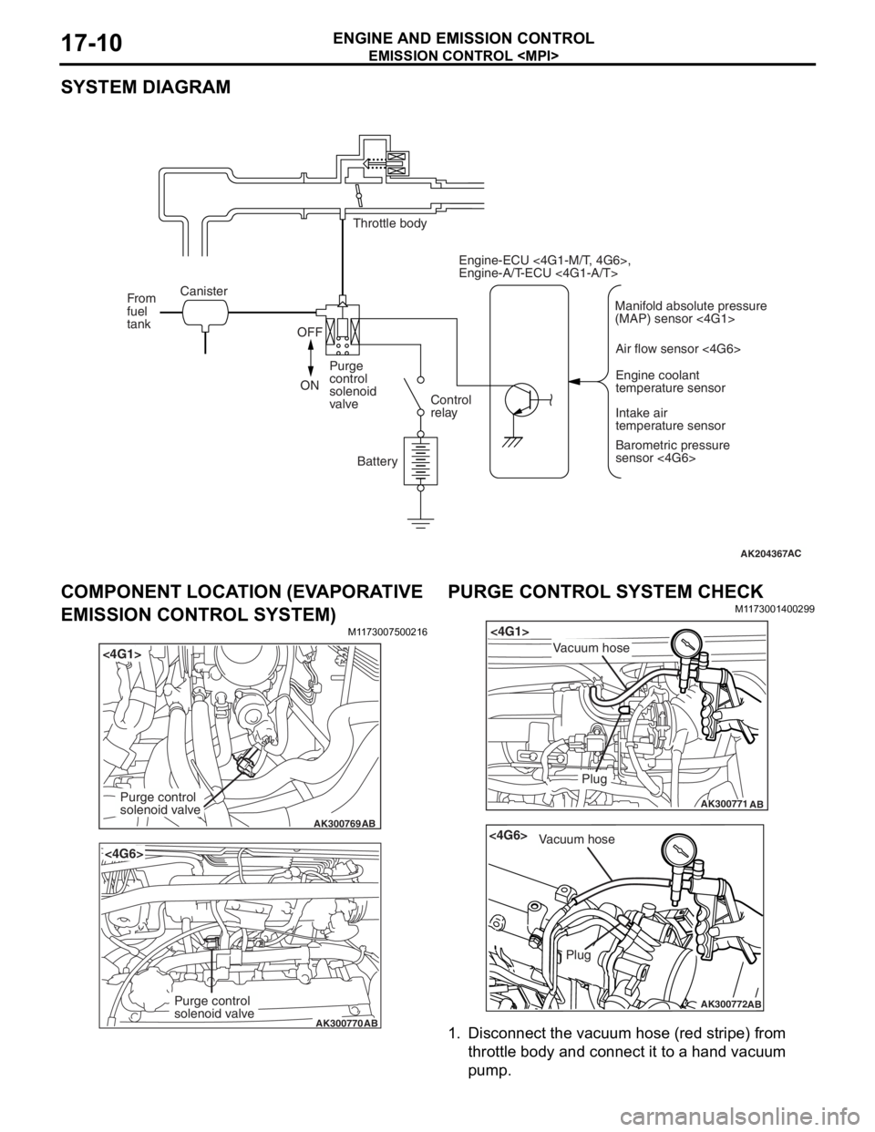
SYSTEM DIAGRAM
AK204367AC
Throttle body
Canister
From
fuel
tank
OFF
ON Purge
control
solenoid
valve
Control
relay
Battery Engine-ECU <4G1-M/T, 4G6>,
Engine-A/T-ECU <4G1-A/T>
Air flow sensor <4G6>Engine coolant
temperature sensor
Intake air
temperature sensor
Barometric pressure
sensor <4G6>
Manifold absolute pressure
(MAP) sensor <4G1>
COMPONENT LOCA
TION (EV A PORA TIVE
EMISSION CONTROL SYSTEM)
M1173 0075 0021 6
AK300769
<4G1>
AB
Purge control
solenoid valve
AK300770
<4G6>
AB
Purge control
solenoid valve
PURGE CONTROL SYSTEM CHECK
M1173 0014 0029 9
AK300771
<4G1>
AB
Plug
Vacuum hose
AK300772
<4G6>
AB
Plug
Vacuum hose
1.Disco nnect the vacu um h o se (re d str i pe) fro m
th rottle body and conne ct it to a h and vacu um
pu m p .
Page 117 of 800
EMISSION CONTROL
ENGINE AND EMISSION CONTROL17-11
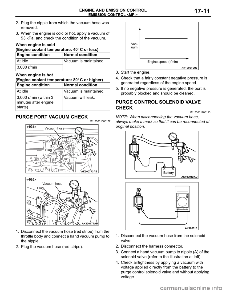
2. Plug the nipple from which the vacuum hose was removed.
3. When the engine is cold or hot, apply a vacuum of 53 kPa, and check the condition of the vacuum.
When engine is cold
(Engine coolant temperature: 40°C or less)
Engine conditionNormal condition
At idleVacuum is maintained.
3,000 r/min
When engine is hot
(Engine coolant temperature: 80°C or higher)
Engine conditionNormal condition
At idleVacuum is maintained.
3,000 r/min (within 3
minutes after engine
starts)Vacuum will leak.
PURGE PORT VACUUM CHECKM1173001500177
AK300773
<4G1>
AB
Plug
Vacuum hose
AK300774
<4G6>
AB
Plug
Vacuum hose
1.Disco nnect th e vacuum ho se (red st ripe) from the
throttle body and connect a hand vacuum pump to
th e nip p le.
2.Plu g the vacuum hose (red stripe).
AK100011AC
Vac-
uum
Engine speed (r/min)
3.S t art the engine.
4.Check t hat a f a irly co nst ant n egative p r essure is
g enerate d regard l ess of the en gine spee d.
5.If no neg ative pressur e is genera t ed, th e port is
p r obably blocked an d sh ould be cleane d.
PURGE CONTROL SOLENOID VA L V E
CHECK
M1173 0017 0019 3
NOTE: Whe n discon nect i ng th e va cuum hose,
always make a mark so th at it can be reconnected at
original p o sition.
AK100012AC
Battery
A
AK100013
1.
Disco nnect the vacu um h o se f r om th e solenoid
valve.
2.Disco nnect the ha rness connector .
3.Con nect a ha nd vacu um pump to nipp le (A) of the
solen o id valve (ref e r to th e ill ust r ation at le f t ).
4.Check a i rtig htness b y app lying a vacuum with
volt age applied d i rectly from t he batt e ry to the
p u rge con t rol so leno id valve an d without app lying
volt age .