ball joint MITSUBISHI LANCER 2006 Owner's Manual
[x] Cancel search | Manufacturer: MITSUBISHI, Model Year: 2006, Model line: LANCER, Model: MITSUBISHI LANCER 2006Pages: 800, PDF Size: 45.03 MB
Page 231 of 800
37-1
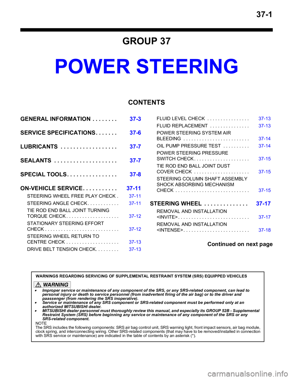
GROUP 37
POWER STEERING
CONTENTS
GENERAL INFORMATION . . . . . . . .37-3
SERVICE SPECIFICATIONS . . . . . . .37-6
LUBRICANTS . . . . . . . . . . . . . . . . . .37-7
SEALANTS . . . . . . . . . . . . . . . . . . . .37-7
SPECIAL TOOLS . . . . . . . . . . . . . . . .37-8
ON-VEHICLE SERVICE . . . . . . . . . . .37-11
STEERING WHEEL FREE PLAY CHECK . 37-11
STEERING ANGLE CHECK . . . . . . . . . . . . 37-11
TIE ROD END BALL JOINT TURNING
TORQUE CHECK . . . . . . . . . . . . . . . . . . . . 37-12
STATIONARY STEERING EFFORT
CHECK . . . . . . . . . . . . . . . . . . . . . . . . . . . . 37-12
STEERING WHEEL RETURN TO
CENTRE CHECK . . . . . . . . . . . . . . . . . . . . 37-13
DRIVE BELT TENSION CHECK. . . . . . . . . 37-13
FLUID LEVEL CHECK . . . . . . . . . . . . . . . . 37-13
FLUID REPLACEMENT . . . . . . . . . . . . . . . 37-13
POWER STEERING SYSTEM AIR
BLEEDING . . . . . . . . . . . . . . . . . . . . . . . . . 37-14
OIL PUMP PRESSURE TEST . . . . . . . . . . 37-14
POWER STEERING PRESSURE
SWITCH CHECK . . . . . . . . . . . . . . . . . . . . . 37-15
TIE ROD END BALL JOINT DUST
COVER CHECK . . . . . . . . . . . . . . . . . . . . . 37-15
STEERING COLUMN SHAFT ASSEMBLY
SHOCK ABSORBING MECHANISM
CHECK . . . . . . . . . . . . . . . . . . . . . . . . . . . . 37-15
STEERING WHEEL . . . . . . . . . . . . . .37-17
REMOVAL AND INSTALLATION
REMOVAL AND INSTALLATION
Continued on next page
WARNINGS REGARDING SERVICING OF SUPPLEMENTAL RESTRAINT SYSTEM (SRS) EQUIPPED VEHICLES
WARNING
•Improper service or maintenance of any component of the SRS, or any SRS-related component, can lead to
personal injury or death to service personnel (from inad vertent firing of the air bag) or to the driver and
paassenger (from renderin g the SRS inoperative).
•Service or maintenance of any SRS component or SRS-related component must be performed only at an
authorized MITSUBISHI dealer.
•MITSUBISHI dealer personnel must thoroughly review th is manual, and especially its GROUP 52B - Supplemental
Restraint System (SRS) before begi nning any service or maintenance of any component of the SRS or any
SRS-related component.
NOTE
The SRS includes the following components: SRS air bag control unit, SRS warning light, front impact sensors, air bag module,
clock spring, and interconnecting wiring. Other SRS-related components (that may have to be removed/installed in connection
with SRS service or maintenance) are indicated in the table of contents by an asterisk (*).
Page 232 of 800
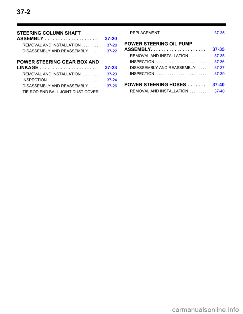
37-2
STEERING COLUMN SHAFT
ASSEMBLY . . . . . . . . . . . . . . . . . . . .37-20
REMOVAL AND INSTALLATION . . . . . . . . 37-20
DISASSEMBLY AND REASSEMBLY . . . . . 37-22
POWER STEERING GEAR BOX AND
LINKAGE . . . . . . . . . . . . . . . . . . . . . .37-23
REMOVAL AND INSTALLATION . . . . . . . . 37-23
INSPECTION . . . . . . . . . . . . . . . . . . . . . . . 37-24
DISASSEMBLY AND REASSEMBLY . . . . . 37-26
TIE ROD END BALL JOINT DUST COVER
REPLACEMENT . . . . . . . . . . . . . . . . . . . . . 37-35
POWER STEERING OIL PUMP
ASSEMBLY. . . . . . . . . . . . . . . . . . . . .37-35
REMOVAL AND INSTALLATION . . . . . . . . 37-35
INSPECTION. . . . . . . . . . . . . . . . . . . . . . . . 37-36
DISASSEMBLY AND REASSEMBLY . . . . . 37-37
INSPECTION. . . . . . . . . . . . . . . . . . . . . . . . 37-39
POWER STEERING HOSES . . . . . . .37-40
REMOVAL AND INSTALLATION . . . . . . . . 37-40
Page 236 of 800

SERVICE SPECIFICATIONS
POWER STEERING37-6
SERVICE SPECIFICATIONS
M1372000300795
ItemStandard valueLimit
Steering wheel free
play mmWith engine running−30
With engine stopped10 or less−
Steering angleInner wheelInvite39°30' ± 1°30'−
Intense (LH drive vehicles)33°40' +1°00'/-2°00'−
Intense (RH drive vehicles)37°00' +1°00'/-2°00'−
Outer wheel
(reference)Invite32°30'−
Intense (LH drive vehicles)28°46'−
Intense (RH drive vehicles)30°00'−
Toe-inAt the centre of tyre tread mm1 ± 2−
Toe-angle (per wheel)0°03' ± 06'−
Tie rod end ball joint turning torque N⋅m0.5 − 2.5−
Tie rod swing resistance N [Tie rod swing torque N⋅m]8 − 27 [1.5 − 4.9]−
Stationary steering effort N [Fluctuation allowance N]29 or less [5.9 or less]−
Oil pump pressure
MPa (750
± 100 r/min.)
Oil pump relief pressure8.8 − 9.5−
Pressure under no-load conditions0.2 − 0.7−
Steering gear retention hydraulic pressure8.8 − 9.5−
Oil pressure switch operating pressure
MPaOFF → ON1.5 − 2.0−
ON → OFF0.7 − 2.0−
Steering gear total pinion torque N⋅m
[Change in torque N
⋅m]
Invite0.8 − 2.1 [0.6 or less]−
Intense0.7 − 2.1 [0.6 or less]−
Opening dimension of special tool boot band crimping tool (MB991561)
mm2.9−
Band crimped width mm2.4 − 2.8−
Page 237 of 800

LUBRICANTS
POWER STEERING37-7
LUBRICANTS
M1372000400350
ItemSpecified lubricantQuantity
Power steering fluidATF DEXRON III or DEXRON IIApproximately 1.0 L
Steering gearBearingATF DEXRON III or DEXRON IIAs required
O-ring and seal ring
Oil seal
Special tool (MB991212,
MB991213)
Pinion and valve assembly
seal ring part
BellowsSilicon greaseAs required
Tie rod end ball jointMultipurpose grease SAE J310,
NLGI No.2 or equivalentAs required
Oil pumpFriction surface of rotor vane,
cam ring and pump coverATF DEXRON III or DEXRON IIAs required
O-ring
SEALANTS
M1372000500357
ItemSpecified sealant
Steering shaft cover assembly bolt hole on the toeboard3M ATD Part No.8513 or equivalent
Steering gearEnd plug3M ATD Part No.8661 or equivalent
Rack support cover
Page 238 of 800
SPECIAL TOOLS
POWER STEERING37-8
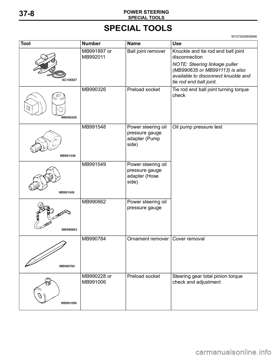
SPECIAL TOOLS
M1372000600666
ToolNumberNameUse
AC106827
MB991897 or
MB9920
1 1Ball j o in t remo verKnuckle and tie rod e nd ball joint
discon
nection
NOTE: St eering linkage pu lle r
(MB990 635 o r MB991 1 13) is also
ava
ilab
l e to disconn ect knuckle and
tie ro
d end ball joint.
MB990326
MB9903 26Prel oad socketTi e rod end b a ll join t turning torq ue
che
c k
MB991548
MB9915 48Powe r stee ring oil
pressure g
auge
adapte
r (Pump
sid
e )Oil pump pre ssu re test
MB991549
MB991549Powe r stee ring oil
pressure g
auge
adapte
r (Hose
sid
e )
MB990662
MB9906 62Powe r stee ring oil
pressure g
auge
MB990784
MB990784Ornament removerCover removal
MB991006
MB9902 28 or
MB9910
06Prel oad socketSt e e ring gear to t a l pinion torque
che
ck and ad justmen t
Page 242 of 800
ON-VEHICLE SERVICE
POWER STEERING37-12
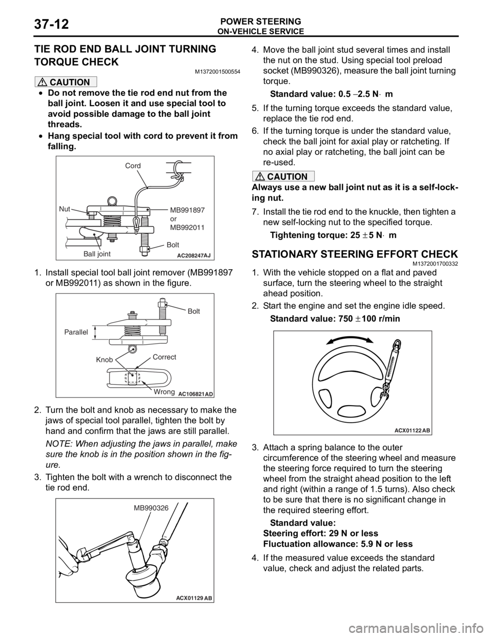
TIE ROD END BALL JOINT TURNING
TORQUE CHECK
M1372001500554
CAUTION
•Do not remove the tie rod end nut from the
ball joint. Loosen it and use special tool to
avoid possible damage to the ball joint
threads.
•
AC208247AJ
CordBoltMB991897
or
MB992011
Nut
Ball joint
Hang special tool with cord to prevent it from
falling.
1. Install special tool ball joint remover (MB991897 or MB992011) as shown in the figure.
AC106821
Knob
Parallel
Bolt
Correct Wrong
AD
2. Turn the bolt and knob as necessary to make the jaws of special tool parallel, tighten the bolt by
hand and confirm that the jaws are still parallel.
NOTE: When adjusting the jaws in parallel, make
sure the knob is in the position shown in the fig
-
ure.
3. Tighten the bolt with a wrench to disconnect the tie rod end.
ACX01129 AB
MB990326
4. Move the ball joint stud several times and install
the nut on the stud. Using special tool preload
socket (MB990326), measure the ball joint turning
torque.
Standard value: 0.5 − 2.5 N⋅m
5. If the turning torque exceeds the standard value, replace the tie rod end.
6. If the turning torque is under the standard value, check the ball joint for axial play or ratcheting. If
no axial play or ratcheting, the ball joint can be
re-used.
CAUTION
Always use a new ball joint nut as it is a self-lock-
ing nut.
7. Install the tie rod end to the knuckle, then tighten a new self-locking nut to the specified torque.
Tightening torque: 25 ± 5 N⋅m
STATIONARY STEERING EFFORT CHECKM1372001700332
1. With the vehicle stopped on a flat and paved
surface, turn the steering wheel to the straight
ahead position.
2. Start the engine and set the engine idle speed.
Standard value: 750 ± 100 r/min
ACX01122 AB
3. Attach a spring balance to the outer
circumference of the steering wheel and measure
the steering force required to turn the steering
wheel from the straight ahead position to the left
and right (within a range of 1.5 turns). Also check
to be sure that there is no significant change in
the required steering effort.
Standard value:
Steering effort: 29 N or less
Fluctuation allowance: 5.9 N or less
4. If the measured value exceeds the standard value, check and adjust the related parts.
Page 245 of 800
ON-VEHICLE SERVICE
POWER STEERING37-15
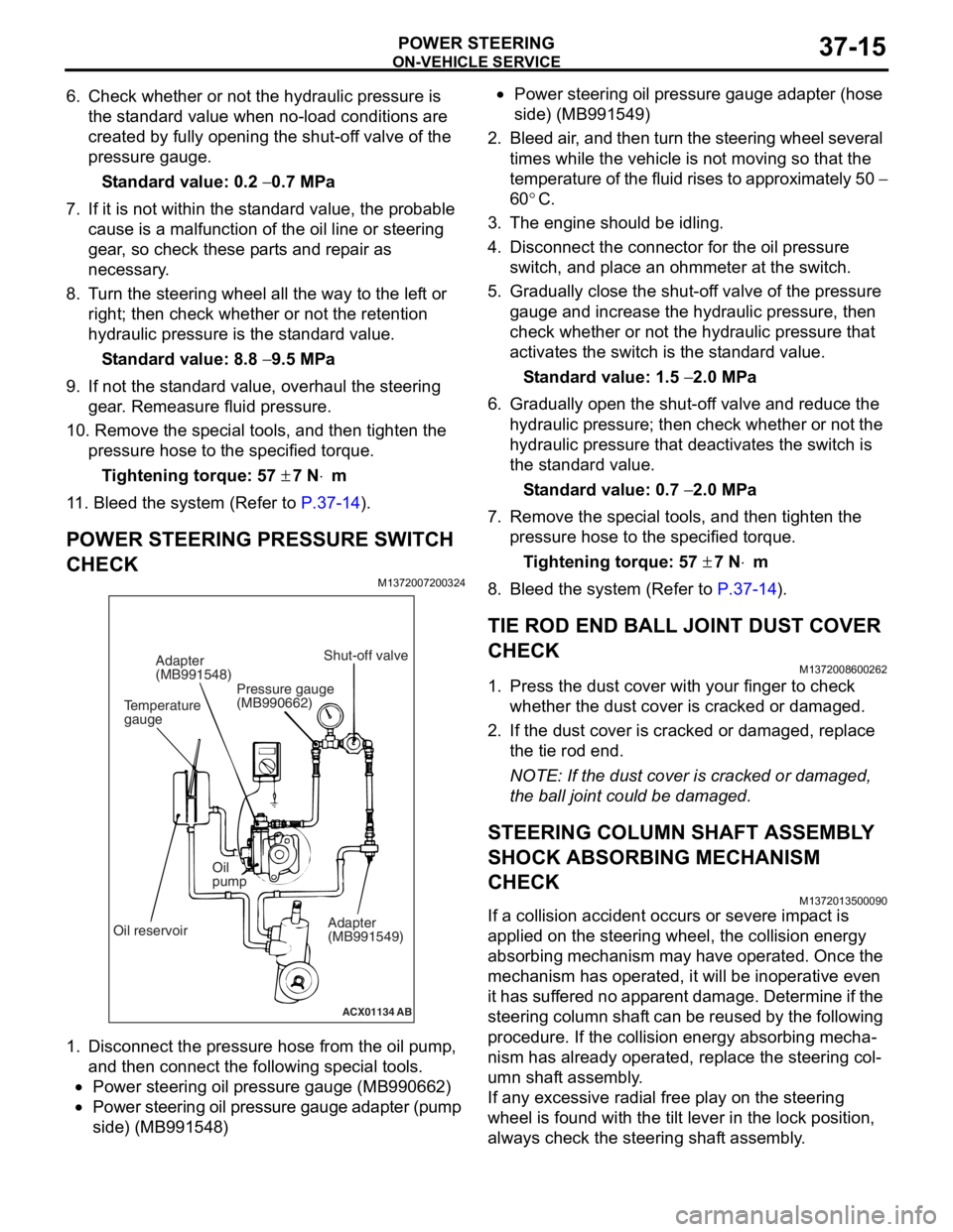
6. Check whether or not the hydraulic pressure is the standard value when no-load conditions are
created by fully opening the shut-off valve of the
pressure gauge.
Standard value: 0.2 − 0.7 MPa
7. If it is not within the standard value, the probable cause is a malfunction of the oil line or steering
gear, so check these parts and repair as
necessary.
8. Turn the steering wheel all the way to the left or right; then check whether or not the retention
hydraulic pressure is the standard value.
Standard value: 8.8 − 9.5 MPa
9. If not the standard value, overhaul the steering gear. Remeasure fluid pressure.
10. Remove the special tools, and then tighten the
pressure hose to the specified torque.
Tightening torque: 57 ± 7 N⋅m
11. Bleed the system (Refer to P.37-14).
POWER STEERING PRESSURE SWITCH
CHECK
M1372007200324
ACX01134 AB
Temperature
gaugeAdapter
(MB991548)
Oil reservoir Oil
pump
Adapter
(MB991549)
Shut-off valve
Pressure gauge
(MB990662)
1. Disco nnect the pre s sure hose from the oil pump ,
an d then con nect the followin g sp ecial too l s.
•Power steering oil pressure gauge (MB990 662)
•Power steering oil pressure gauge ad apter (pump
side) (MB99154
8)
•Power steering oil pressure gaug e a dapte r (ho s e
side) (MB99154
9)
2. Bleed air , and the n turn t he steering wheel several
times while the vehicle is not moving so that the
tempe r atu r e o f th e flu i d rise s to approximately 50
−
60
°C.
3. Th e engine should be idling.
4.Disco nnect the conne ctor fo r the o il pr essure
switch , and p l ace an o h mmeter a t the switch .
5.Gradua lly close the shut-of f valve of the pressure
g auge a nd in crease the hyd r aulic pre ssu re, the n
check wheth e r or no t the h y drau lic pressure that
a c tivates the switch is the st a ndard valu e.
St andard va lue: 1.5 − 2.0 MPa
6.Gradua lly open the shut-of f va lve and re duce the
h y drau lic p r essure; then check whethe r o r n o t the
h y drau lic pressure that de activate s the switch is
th e st and ard va lue.
St andard va lue: 0.7 − 2.0 MPa
7.Remove the special tools, and then tighten the
p r essure hose to the specified torque .
Ti ghte n ing torque: 57 ± 7 N⋅m
8.Bleed the system (Refer to P.37-14).
TIE ROD END BALL JOINT DUST COVER
CHECK
M13720086 0026 2
1.Press th e dust co ver wit h you r fing er to check
whet her the dust cover is cra cke d or da mage d.
2.If the du st cover is cracked o r damaged, repla c e
th e tie rod end .
NOTE: If the dust cover is cra cke d or da mag ed,
th
e ball jo int could be da mage d.
STEERING COLUMN SHAFT ASSEMBL Y
SHOCK ABSORBING MECHANISM
CHECK
M13720135 0009 0
If a collision accid ent occu rs or seve re imp a ct is
applied on
the steering w heel, the collision energy
abso
r bing mechanism ma y h a ve opera t ed. Once the
mechanism
has o perate d , it will b e ino perative e v en
it has
suf f er ed no app a r en t d a mage . De termin e if the
steering colu
mn shaf t can b e reused b y th e following
proce
dure. If the collision en ergy a b sor b ing mecha
-
nism has already operated, rep l ace the steering col-
umn shaft assembly .
If any excessive radial fre e pla y on the steering
wh
eel is fo und with the tilt lever in the lock po sit i on,
always ch
eck the steering shaf t assembly .
Page 255 of 800
POWER STEERING GEAR BOX AND LINKAGE
POWER STEERING37-25
NOTE: When measuring, remove the bellows from
the rack housing. Measure the pinion torque through
the whole stroke of the rack.
If the measured value is not within the standard
range, first adjust the rack support cover, and then
check the total pinion torque again.
If the total pinion torque cannot be adjusted to within
the standard range by adjusting the rack support
cover, check the rack support cover, rack support
spring, rack support and replace any parts if neces
-
sary.
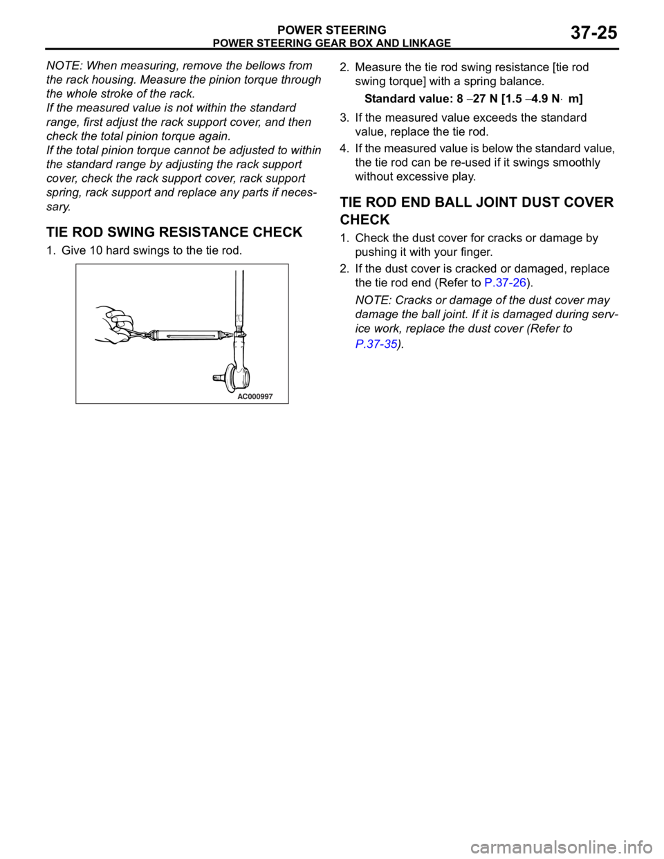
TIE ROD SWING RESISTANCE CHECK
1. Give 10 hard swings to the tie rod.
AC000997
2. Measure the tie ro d swin g resist ance [tie rod
swing to rque] with a spring bala n ce.
St andard va lue: 8 − 27 N [1.5 − 4.9 N⋅m]
3.If the measu r ed value exceeds the st a ndard
value , replace the tie rod.
4. If the measured value is below the st a ndard valu e,
th e tie rod can be re-use d if it swings smo o thly
wit hout e xce ssive play .
TIE ROD END BALL JOINT DUST COVER
CHECK
1.Check t he dust co ver f o r cracks or da mage by
p u shing it with your finger .
2.If the du st cover is cracked o r damaged, repla c e
th e tie rod end (Refer to
P.37-26).
NOTE: Cracks or dama ge of t he dust co ver may
d
a
mag
e the ball joint. If it is da mag ed du ring serv
-
ice work, replace the du st cove r (Re f er to
P.37-35).
Page 265 of 800
POWER STEERING OIL PUMP ASSEMBLY
POWER STEERING37-35
TIE ROD END BALL JOINT DUST COVER
REPLACEMENT
M1372008200327
If the dust cover is damaged accidentally during
service work, replace the dust cover as follows:
AC001012AB
MB990776
1.App l y specified grea se to the lip an d inside of the
d u st c o ve r .
Specified grease:
Mu l t i p u r po se g r ea se SAE J3 10 , NL GI No .2 or
equival
ent
2.Drive in the d u st cover with special tool f r ont axle
b a se (MB9907 76) unt il it is fully seated .
3.Check t he dust co ver f o r cracks or da mage by
p u shing it with your finger .
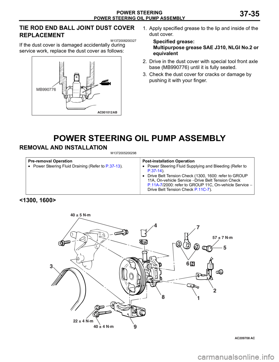
POWER STEERING OIL PUMP ASSEMBL Y
REMOVA L AND INST ALLA TIONM13720052 0029 8
Pre-removal Operation
•Power Steering Fluid Draining (Refer to P.37-13).
Post-installation Operation
•Power Steering Fluid Supplying and Bleeding (Refer to
P.37-14).
•Drive Belt Tension Check (1300, 1600: refer to GROUP
11A, On-vehicle Service
− Drive Belt Tension Check
P.11A-7/2000: refer to GROUP 11C, On-vehicle Service − Drive Belt Tension Check P.11C-7).
<1300, 1600>
AC209708
87
1 2
3 4
5
6
57 ± 7 N·m
40 ± 4 N·m
22 ± 4 N·m
N
9
40 ± 5 N·m
AC