torque MITSUBISHI LANCER 2006 Owner's Manual
[x] Cancel search | Manufacturer: MITSUBISHI, Model Year: 2006, Model line: LANCER, Model: MITSUBISHI LANCER 2006Pages: 800, PDF Size: 45.03 MB
Page 201 of 800

SERVICE SPECIFICATIONS
REAR SUSPENSION34-3
SPECIFICATION
COIL SPRING
ItemSedanWagon
InviteIntenseInviteIntense
Wire diameter mm10101010
Average diameter mm78 − 9078 − 9078 − 9078 − 90
Free length mm359331377368
SERVICE SPECIFICATIONS
M1341000300733
ItemStandard value
Camber (Difference between right and left within 30') −0°40' ± 0°30'
Toe-inAt the centre of tyre tread mm3 ± 2
Toe-angle (per wheel)0°08' ± 0°05'
Thrust angle0°00' ± 0°09'
Control link pillow ball bushing starting torque
Upper arm pillow ball bushing starting torque
Lower arm pillow ball bushing starting torque N⋅m0.5 − 3.0
Protruding length of stabilizer link bolt mm6 − 8
Stabilizer link ball joint continuous turning torque N⋅m0.5 − 1.5
LUBRICANT
M1341000400172
ItemSpecified lubricantQuantity
Stabilizer link ball joint (inside of dust cover)Multipurpose grease SAE J310, NLGI No.2
or equivalentAs required
Page 202 of 800
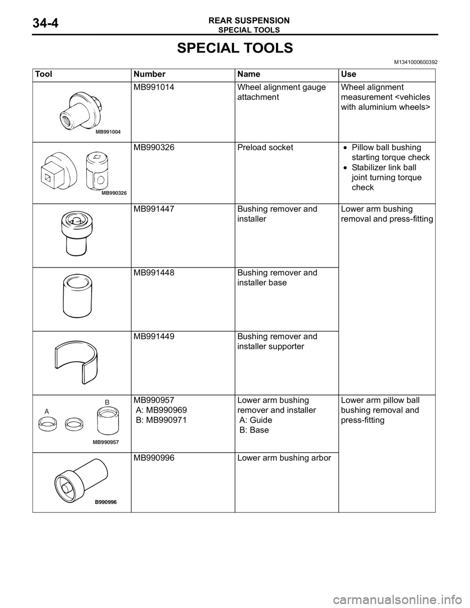
SPECIAL TOOLS
REAR SUSPENSION34-4
SPECIAL TOOLS
M1341000600392
ToolNumberNameUse
MB991004
MB991014Wheel alignme n t gau ge
att
a chmentWheel alig nme n t
measurement
MB990326
MB990326Prel oad socket•Pillow ba ll b u shing
st
a r ting t o rque check
•St abil i ze r lin k ba ll
joint t
u rnin g torque
check
MB991447Bushing remove r and
inst
al lerLo wer arm bushing
re
moval and press-fit t ing
MB991448Bushing remove r and
inst
al ler b a se
MB991449Bushing remove r and
inst
aller suppo rter
MB990957
A B
MB990
957
A: MB9909 69
B: MB990971
Lower arm bushing
remover an
d inst a lle r
A: Guide
B: Base
Lo wer arm pillow ball
b
u shing removal an d
p
r ess-fitting
B990996
MB990 996Lower arm bushing arbor
Page 204 of 800
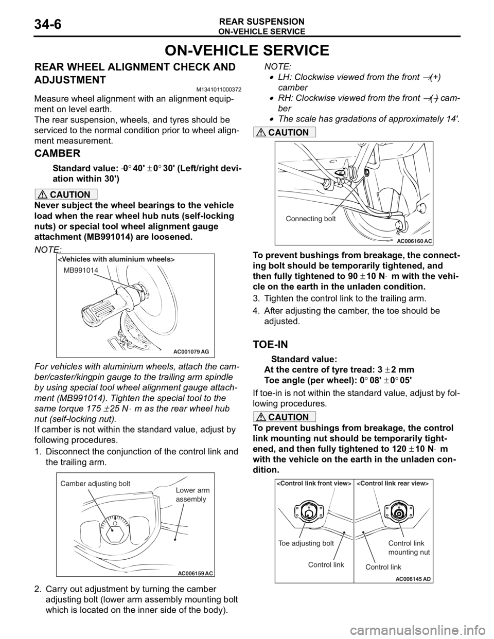
ON-VEHICLE SERVICE
REAR SUSPENSION34-6
ON-VEHICLE SERVICE
REAR WHEEL ALIGNMENT CHECK AND
ADJUSTMENT
M1341011000372
Measure wheel alignment with an alignment equip-
ment on level earth.
The rear suspension, wheels, and tyres should be
serviced to the normal condition prior to wheel align
-
ment measurement.
CAMBER
Standard value: −0°40' ± 0°30' (Left/right devi-
ation within 30')
CAUTION
Never subject the wheel bearings to the vehicle
load when the rear wheel hub nuts (self-locking
nuts) or special tool wheel alignment gauge
attachment (MB991014) are loosened.
NOTE:
AC001079
MB991014
AG
For vehicles with aluminium wheels, attach the cam-
ber/caster/kingpin gauge to the trailing arm spindle
by using special tool wheel alignment gauge attach
-
ment (MB991014). Tighten the special tool to the
same torque 175
± 25 N⋅m as the rear wheel hub
nut (self-locking nut).
If camber is not within the standard value, adjust by
following procedures.
1. Disconnect the conjunction of the control link and the trailing arm.
AC006159 AC
Camber adjusting bolt
Lower arm
assembly
2. Carry out adjustment by turning the camber
adjusting bolt (lower arm assembly mounting bolt
which is located on the inner side of the body).
NOTE: .
•LH: Clockwise viewed from the front → (+)
camber
•RH: Clockwise viewed from the front → (−) cam-
ber
•
AC006160 AC
Connecting bolt
The scale has gradations of approximately 14'.
CAUTION
To prevent bushings from breakage, the connect-
ing bolt should be temporarily tightened, and
then fully tightened to 90
± 10 N⋅m with the vehi-
cle on the earth in the unladen condition.
3. Tighten the control link to the trailing arm.
4. After adjusting the camber, the toe should be
adjusted.
TOE-IN
Standard value:
At the centre of tyre tread: 3 ± 2 mm
Toe angle (per wheel): 0°08' ± 0°05'
If toe-in is not within the standard value, adjust by fol-
lowing procedures.
CAUTION
To prevent bushings from breakage, the control
link mounting nut should be temporarily tight
-
ened, and then fully tightened to 120 ± 10 N⋅m
with the vehicle on the earth in the unladen con
-
dition.
AC006145 AD
Control link
Toe adjusting boltControl link
Control link
mounting nut
Page 208 of 800
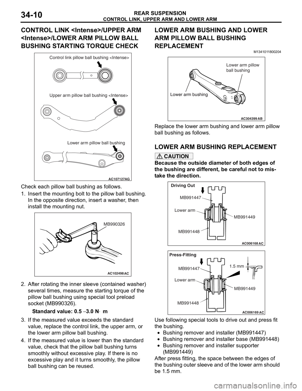
CONTROL LINK, UPPER ARM AND LOWER ARM
REAR SUSPENSION34-10
CONTROL LINK
BUSHING STARTING TORQUE CHECK
AC107127AG
Lower arm pillow ball bushing
Upper arm pillow ball bushing
Che
c k each pillow ball bu shing as follows.
1.In sert the mou n ting bo lt t o th e pillo w ball b u shing.
In the op posite direction, inse rt a wash er , the n
inst all the moun ting n u t.
AC102498AC
MB990326
2.Af ter rot a ting the inner sleeve (cont aine d washer)
seve ral times, me asure the st a r ting torque o f the
pillow ball bushing using sp ecial to ol pre l oad
socket (MB990326 ).
St andard va lue: 0.5 − 3.0 N⋅m
3.If the measu r ed value exceeds the st a ndard
value , replace the control lin k, the upper arm, o r
th e lower a r m pillo w ball bushing.
4.If the measu r ed value is lower tha n the st andard
value , che c k that th e pillow ba ll b u shing turn s
smoo thly withou t excessive play . If the r e is no
exce ssive play and it turns smooth l y , the pillow
ba ll b u shing can be reused.
LOWER ARM BUSHING AND LOWER
ARM PILLOW BALL BUSHING
REPLACEMENT
M134101 18 0020 4
AC304399AB
Lower arm bushing Lower arm pillow
ball bushing
Lower arm bushing
Re place the lower a r m bu shing an d lower arm p illow
ball bushing
as fo llows.
LO WER ARM BUSHING REPLACEM ENT
CAUTION
Because the outside diameter of both edges of
the bushing are different, be careful not to mis
-
take the direction.
AC006168
AC
Driving Out
MB991447
Lower arm
MB991448 MB991449
AC006169
AC
1.5 mm
Press-Fitting
MB991447
Lower arm
MB991448 MB991449
Use following special tools to drive out and press fit
the bushing.
•Bushing remover and installer (MB991447)
•Bushing remover and installer base (MB991448)
•Bushing remover and installer supporter
(MB991449)
After press fitting, the space between the edges of
the bushing outer sleeve and of the lower arm should
be 1.5 mm.
Page 218 of 800
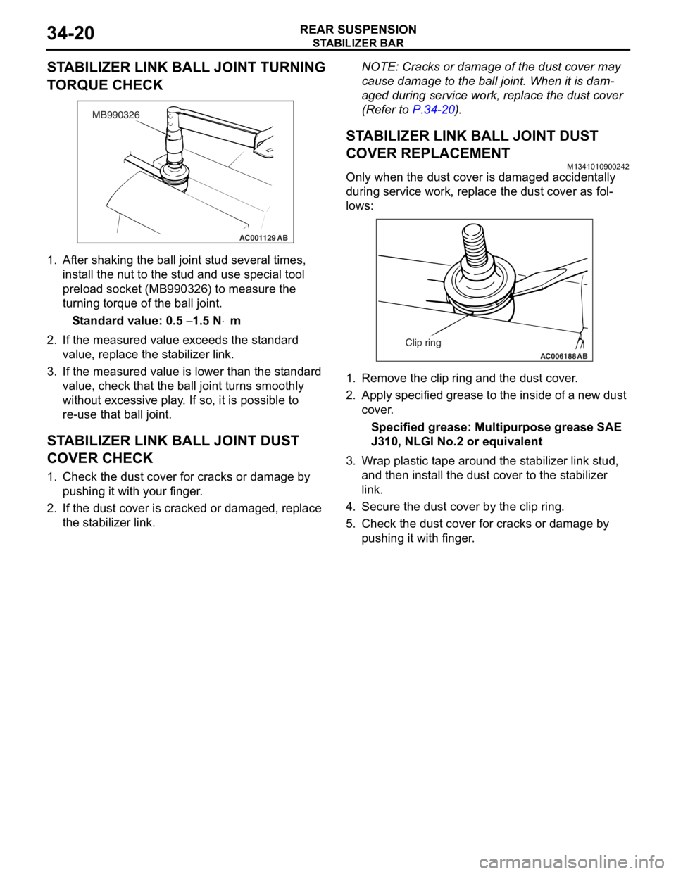
STABILIZER BAR
REAR SUSPENSION34-20
STABILIZER LINK BALL JOINT TURNING
TORQUE CHECK
AC001129
MB990326
AB
1.Af ter shaking th e ball jo int stud seve ral times,
inst all the n u t to t he st ud and use special tool
pre l oad socket (MB990 326) to measure th e
tu rning torque of the ball joint.
St andard va lue: 0.5 − 1.5 N⋅m
2.If the measu r ed value exceeds the st a ndard
value , replace the st ab ilizer link.
3.If the measu r ed value is lower tha n the st andard
value , che c k that th e ball jo int tu rns smoo thly
wit hout exce ssive play . I f so, it is possible to
re- u se t hat ball joint.
STABILIZER LINK BALL JOINT DUST
COVER CHECK
1. Check t he dust co ver fo r cracks or da mage by
pu shing it with your finger .
2.If the du st cover is cracked o r damaged, replace
th e st abilizer link.
NOTE: Cracks or dama ge of t he dust co ver may
cause damage to the b a ll join t. When it is dam
-
aged du ring service wo rk, rep l ace the d u st cover
(Refe
r to
P.34-2 0).
STABILIZER LINK BALL JOINT DUST
COVER REPLACEM
ENT
M13410109 0024 2
Only when the du st cover is d a ma ged accident ally
during
service work, repla c e th e dust cover as fol
-
lows:
AC006188 AB
Clip ring
1.Remove the clip ring and the dust cover .
2.App l y specified g r ease to t he insid e of a ne w dust
cov e r .
Specified grease: Multipurpos e grease SAE
J310,
NLGI No.2 o r e quivale n t
3.W r ap plast i c t ape aroun d the st a b ilize r lin k stud,
a nd then inst a ll th e dust co ver to the st a b ilizer
li nk.
4.Secure th e dust co ver by the clip rin g .
5.Check t he dust co ver f o r cracks or da mage by
p u shing it with finger .
Page 231 of 800
37-1
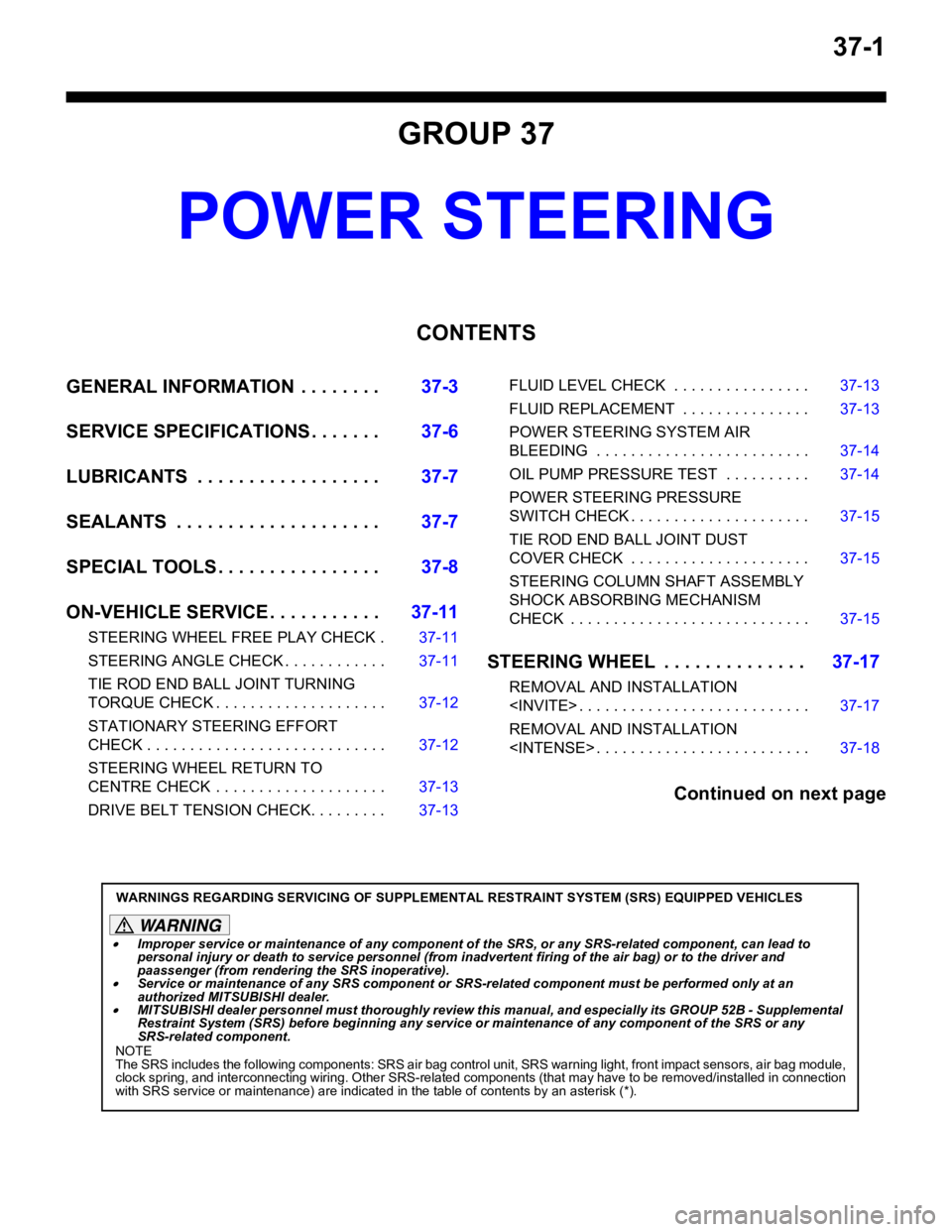
GROUP 37
POWER STEERING
CONTENTS
GENERAL INFORMATION . . . . . . . .37-3
SERVICE SPECIFICATIONS . . . . . . .37-6
LUBRICANTS . . . . . . . . . . . . . . . . . .37-7
SEALANTS . . . . . . . . . . . . . . . . . . . .37-7
SPECIAL TOOLS . . . . . . . . . . . . . . . .37-8
ON-VEHICLE SERVICE . . . . . . . . . . .37-11
STEERING WHEEL FREE PLAY CHECK . 37-11
STEERING ANGLE CHECK . . . . . . . . . . . . 37-11
TIE ROD END BALL JOINT TURNING
TORQUE CHECK . . . . . . . . . . . . . . . . . . . . 37-12
STATIONARY STEERING EFFORT
CHECK . . . . . . . . . . . . . . . . . . . . . . . . . . . . 37-12
STEERING WHEEL RETURN TO
CENTRE CHECK . . . . . . . . . . . . . . . . . . . . 37-13
DRIVE BELT TENSION CHECK. . . . . . . . . 37-13
FLUID LEVEL CHECK . . . . . . . . . . . . . . . . 37-13
FLUID REPLACEMENT . . . . . . . . . . . . . . . 37-13
POWER STEERING SYSTEM AIR
BLEEDING . . . . . . . . . . . . . . . . . . . . . . . . . 37-14
OIL PUMP PRESSURE TEST . . . . . . . . . . 37-14
POWER STEERING PRESSURE
SWITCH CHECK . . . . . . . . . . . . . . . . . . . . . 37-15
TIE ROD END BALL JOINT DUST
COVER CHECK . . . . . . . . . . . . . . . . . . . . . 37-15
STEERING COLUMN SHAFT ASSEMBLY
SHOCK ABSORBING MECHANISM
CHECK . . . . . . . . . . . . . . . . . . . . . . . . . . . . 37-15
STEERING WHEEL . . . . . . . . . . . . . .37-17
REMOVAL AND INSTALLATION
REMOVAL AND INSTALLATION
Continued on next page
WARNINGS REGARDING SERVICING OF SUPPLEMENTAL RESTRAINT SYSTEM (SRS) EQUIPPED VEHICLES
WARNING
•Improper service or maintenance of any component of the SRS, or any SRS-related component, can lead to
personal injury or death to service personnel (from inad vertent firing of the air bag) or to the driver and
paassenger (from renderin g the SRS inoperative).
•Service or maintenance of any SRS component or SRS-related component must be performed only at an
authorized MITSUBISHI dealer.
•MITSUBISHI dealer personnel must thoroughly review th is manual, and especially its GROUP 52B - Supplemental
Restraint System (SRS) before begi nning any service or maintenance of any component of the SRS or any
SRS-related component.
NOTE
The SRS includes the following components: SRS air bag control unit, SRS warning light, front impact sensors, air bag module,
clock spring, and interconnecting wiring. Other SRS-related components (that may have to be removed/installed in connection
with SRS service or maintenance) are indicated in the table of contents by an asterisk (*).
Page 236 of 800

SERVICE SPECIFICATIONS
POWER STEERING37-6
SERVICE SPECIFICATIONS
M1372000300795
ItemStandard valueLimit
Steering wheel free
play mmWith engine running−30
With engine stopped10 or less−
Steering angleInner wheelInvite39°30' ± 1°30'−
Intense (LH drive vehicles)33°40' +1°00'/-2°00'−
Intense (RH drive vehicles)37°00' +1°00'/-2°00'−
Outer wheel
(reference)Invite32°30'−
Intense (LH drive vehicles)28°46'−
Intense (RH drive vehicles)30°00'−
Toe-inAt the centre of tyre tread mm1 ± 2−
Toe-angle (per wheel)0°03' ± 06'−
Tie rod end ball joint turning torque N⋅m0.5 − 2.5−
Tie rod swing resistance N [Tie rod swing torque N⋅m]8 − 27 [1.5 − 4.9]−
Stationary steering effort N [Fluctuation allowance N]29 or less [5.9 or less]−
Oil pump pressure
MPa (750
± 100 r/min.)
Oil pump relief pressure8.8 − 9.5−
Pressure under no-load conditions0.2 − 0.7−
Steering gear retention hydraulic pressure8.8 − 9.5−
Oil pressure switch operating pressure
MPaOFF → ON1.5 − 2.0−
ON → OFF0.7 − 2.0−
Steering gear total pinion torque N⋅m
[Change in torque N
⋅m]
Invite0.8 − 2.1 [0.6 or less]−
Intense0.7 − 2.1 [0.6 or less]−
Opening dimension of special tool boot band crimping tool (MB991561)
mm2.9−
Band crimped width mm2.4 − 2.8−
Page 238 of 800
SPECIAL TOOLS
POWER STEERING37-8
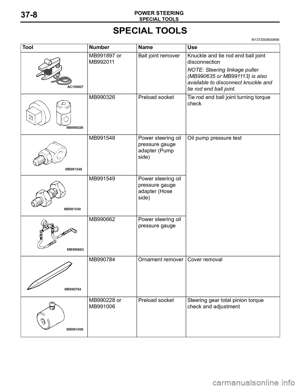
SPECIAL TOOLS
M1372000600666
ToolNumberNameUse
AC106827
MB991897 or
MB9920
1 1Ball j o in t remo verKnuckle and tie rod e nd ball joint
discon
nection
NOTE: St eering linkage pu lle r
(MB990 635 o r MB991 1 13) is also
ava
ilab
l e to disconn ect knuckle and
tie ro
d end ball joint.
MB990326
MB9903 26Prel oad socketTi e rod end b a ll join t turning torq ue
che
c k
MB991548
MB9915 48Powe r stee ring oil
pressure g
auge
adapte
r (Pump
sid
e )Oil pump pre ssu re test
MB991549
MB991549Powe r stee ring oil
pressure g
auge
adapte
r (Hose
sid
e )
MB990662
MB9906 62Powe r stee ring oil
pressure g
auge
MB990784
MB990784Ornament removerCover removal
MB991006
MB9902 28 or
MB9910
06Prel oad socketSt e e ring gear to t a l pinion torque
che
ck and ad justmen t
Page 239 of 800
SPECIAL TOOLS
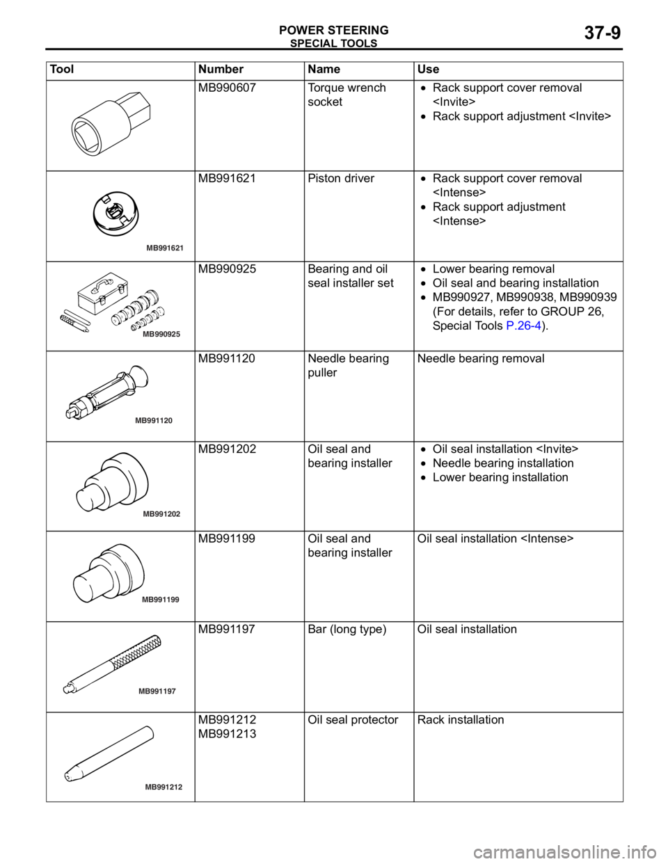
POWER STEERING37-9
MB990607Torque wrench
socket•Rack support cover removal
•Rack support adjustment
MB991621
MB991621Piston driver•Rack suppo rt co ver removal
•Rack support adjustment
MB990925
MB990925Bearing and o il
seal
inst alle r set•Lower bearing re moval
•Oil seal and bearing inst allatio n
•MB 9 9 0 9 2 7 , MB99 09 38, MB9 909 39
(For det
ails, refer to GROUP 26 ,
S
p e c ia l T o ols
P.26-4).
MB991120
MB991120Needle bearing
pullerNeedle bearing remova l
MB991202
MB991202Oil seal an d
bearing in
st aller•Oil seal in st allation
•Need le bearin g inst alla tion
•Lower bearing inst allation
MB991199
AB
MB991199Oil seal an d
bearing in
st allerOil seal inst allatio n
MB991197
MB991197Bar (long type)Oil seal inst allatio n
MB991212
MB991212
MB991213
Oil seal pro t ecto rRack insta llat i on
Tool Num ber Na me Use
Page 241 of 800
ON-VEHICLE SERVICE
POWER STEERING37-11
ON-VEHICLE SERVICE
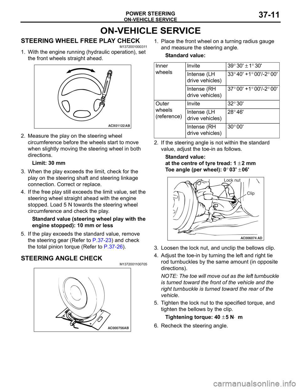
STEERING WHEEL FREE PLAY CHECKM1372001000311
1. With the engine running (hydraulic operation), set the front wheels straight ahead.
ACX01122 AB
2.Measure the play on th e ste e ring wh eel
circumfer ence before the whee ls st a r t to move
when slightly moving the stee ring whe e l in both
direct ions.
Limit: 30 mm
3.Wh en the play exceed s the limit, check fo r the
play on the stee ring shaf t and stee ring linkage
connectio n . Correct or replace .
4.If th e free play still exceeds the limit valu e, set t he
steering wheel stra ight ahead with the engine
stoppe d. Loa d 5 N towards the steer ing whee l
circumfer ence and check the play .
St andard value (steering whee l pla y with the
engine s
t opped): 1 0 mm o r l ess
5.If the play e xce eds the st an dard value , remove
th e ste e ring gear (Refe r to
P.37-23) and check
the tot a l p i nion torqu e (Refer to P.37-26).
STEERING ANGLE CHECKM137200 1 1 0070 5
AC000756AB
1.Place t he fron t wh eel on a tu rning radiu s gau ge
a nd me asure the steering ang le.
St andard va lue:
Inner
wheelsInvite39°30' ± 1°30'
Intense (LH
drive vehicles)33°40' +1°00'/-2°00'
Intense (RH
drive vehicles)37°00' +1°00'/-2°00'
Outer
wheels
(reference)Invite32°30'
Intense (LH
drive vehicles)28°46'
Intense (RH
drive vehicles)30°00'
2.If the steerin g ang le is not within the st a ndard
value , adjust t he toe-in as follows.
St andard va lue:
at the centre of tyre trea d: 1 ± 2 mm
To e angle (p er whee l): 0°03' ± 06'
AC006074 AD
Lock nut
Clip
3.L oose n the lock nut, and un clip the bellows clip .
4.Adjust the toe - in by turning th e lef t an d righ t tie
ro d turnb u ckles by th e sa me a m oun t (in o pposite
directions).
NOTE: The to e will move out as th e lef t turnbuckle
is tur
ned toward the fro n t of th e ve hicle an d the
right tu
rnbuckle is turned toward the rear of the
vehicle.
5. T i ghten the lo ck nut to the specified torque , and
tighten the be llo ws by the clip .
Ti ghte n ing torque: 40 ± 5 N⋅m
6.Recheck the stee ring a ngle .