MITSUBISHI LANCER 2006 Workshop Manual
[x] Cancel search | Manufacturer: MITSUBISHI, Model Year: 2006, Model line: LANCER, Model: MITSUBISHI LANCER 2006Pages: 800, PDF Size: 45.03 MB
Page 381 of 800
DOOR MIRROR
EXTERIOR51-49
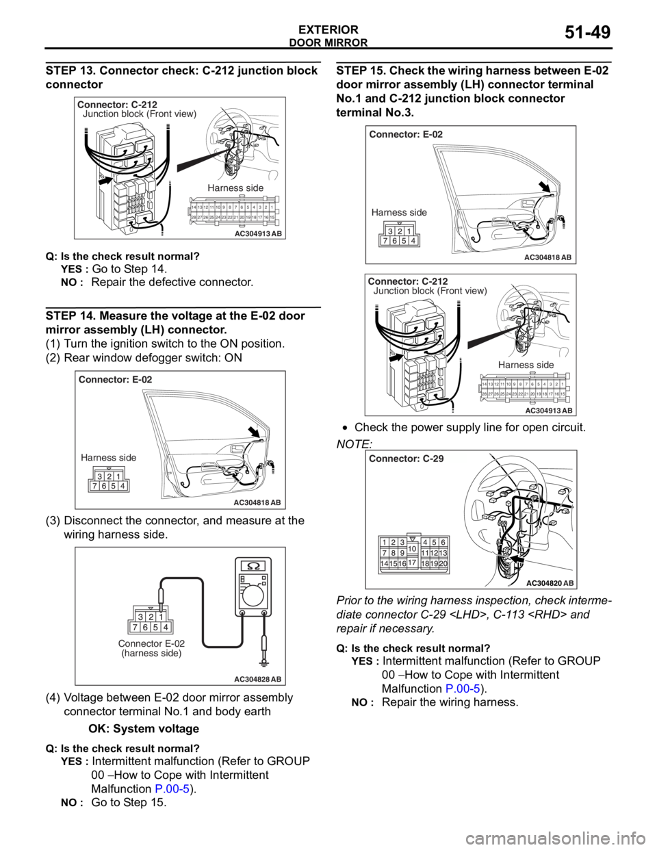
STEP 13. Connector check: C-212 junction block
connector
AC304913
21716151718
201912345
623 222425282627981011141213
Connector: C-212
Harness side
AB
Junction block (Front view)
Q : Is the check result normal?
YES : Go to S t ep 14 .
NO : Repa ir the defective connector .
STEP 14 . Me asure the volt age at the E-02 door
mirror a
ssembl y (LH) conne ctor .
(1)T urn t he ig nition switch to the ON positio n.
(2)R ear win dow defo gger switch : ON
AC304818
Connector: E-02
Harness side
AB
(3) D isconn ect t he co nnector , an d me asure at the
wiring harn e ss side.
AC304828
Connector E-02(harness side)
AB
(4) V olt a g e between E-02 doo r mirror assembly
co nnector termina l No.1 a nd bod y ea rth
OK: System vo lt age
Q: Is the check result normal?
YES : Intermittent ma lfun ctio n (Refer to GROUP
00
− Ho w t o Cope wit h Intermitte nt
Malfunction
P.00-5).
NO : Go to S t ep 15 .
STEP 1 5 . Chec k the wiring ha rnes s betwe en E-02
door mirror assem
bly (LH) con nector termina l
No.
1 and C-21 2 junctio n block connec tor
terminal No.3
.
AC304818
Connector: E-02
Harness side
AB
AC304913
21 716151718
201912345
623 222425282627981011141213
Connector: C-212
Harness side
AB
Junction block (Front view)
•Check th e power supply line fo r open circuit.
NOTE:
AC304820
Connector: C-29
AB
Prior to the wiring harness insp ection, check interme-
diate connector C-29
rep
a ir if necessary .
Q:Is t h e che c k r esu lt n o rmal?
YES : Intermittent malfun ctio n (Refer to GROUP
00
− Ho w to Cope wit h Intermitte nt
Ma
lfunction
P.00-5).
NO : Repa ir th e wirin g harne ss.
Page 382 of 800
DOOR MIRROR
EXTERIOR51-50
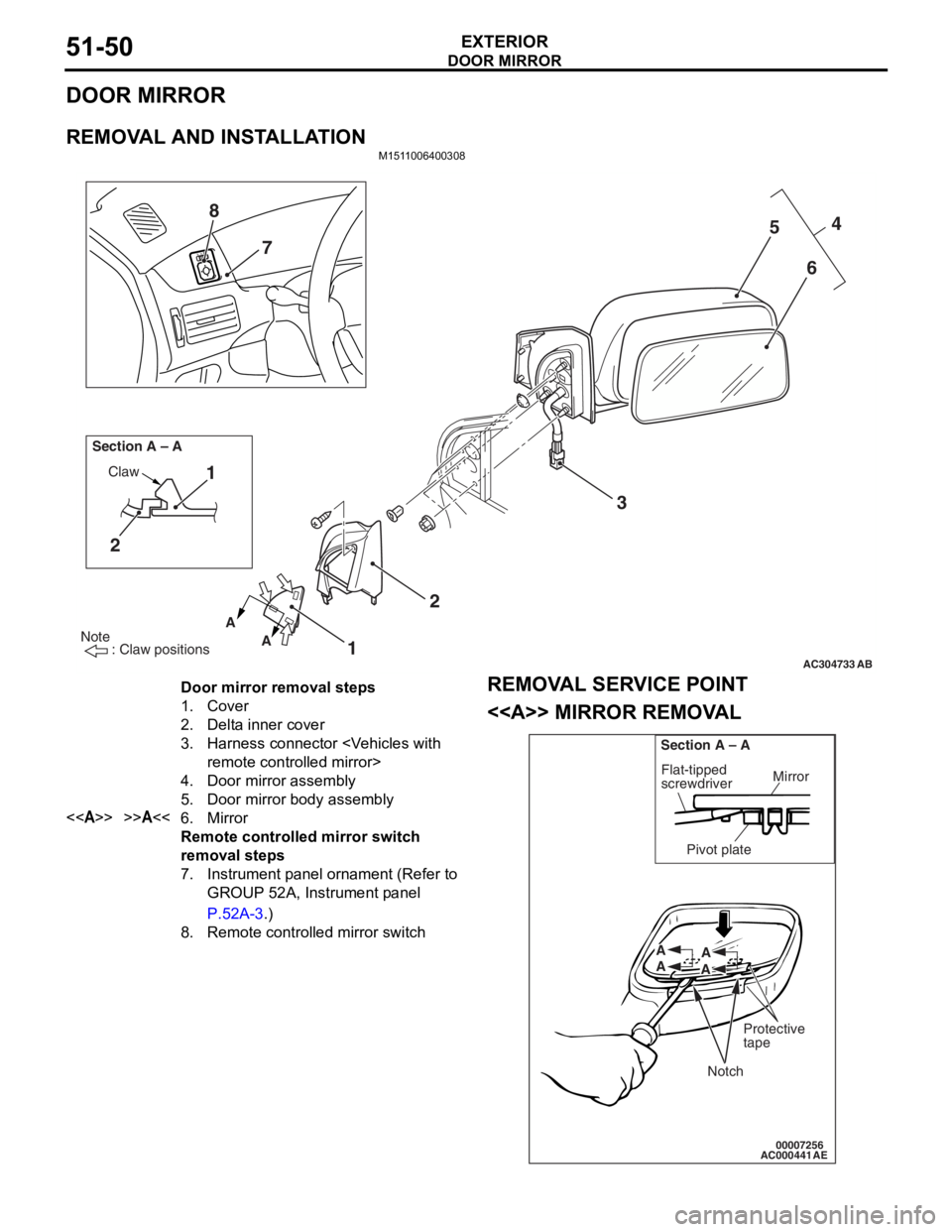
DOOR MIRROR
REMOVAL AND INSTALLATION
M1511006400308
AC304733
Note
: Claw positions
AB
AA
Section A – A
Claw1
2
12 3 4
5
6
7
8
Door mirror removal steps
1.Cover
2.Delta inner cover
3.Harness connector
4.Door mirror assembly
5.Door mirror body assembly
<>>>A<<6.Mirror
Remote controlled mirror switch
removal steps
7.Instrument panel ornament (Refer to
GROUP 52A, Instrument panel
P.52A-3.)
8.Remote controlled mirror switch
REMOV
A L SER VICE POINT
<> MIRROR REMOV A L
AC00044100007256
Mirror
Flat-tipped
screwdriver
Section A – A
Pivot plate
Notch
Protective
tape
A
A A
A
AE
Page 383 of 800
DOOR MIRROR
EXTERIOR51-51
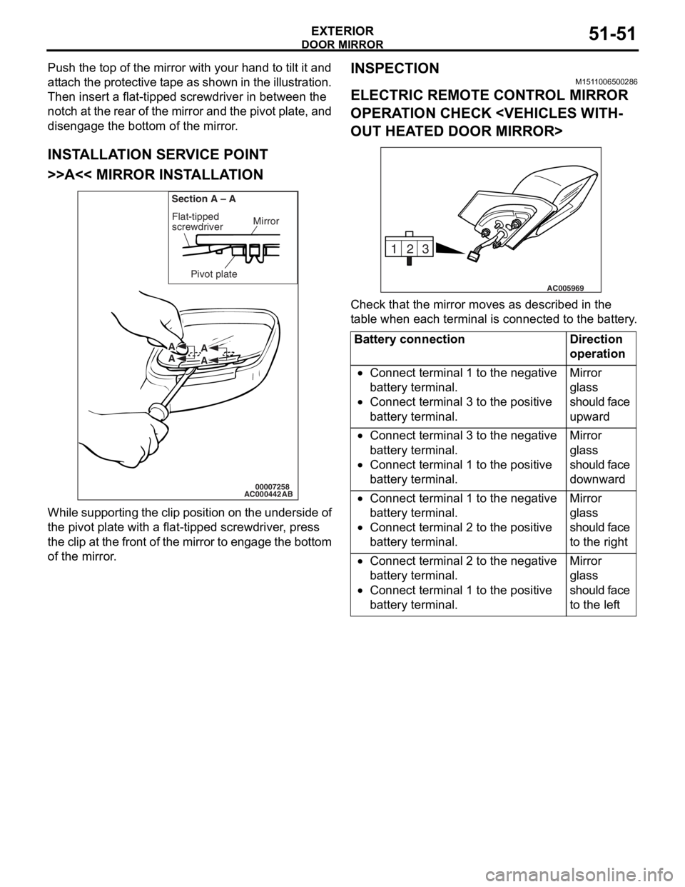
Push the top of the mirror with your hand to tilt it and
attach the protective tape as shown in the illustration.
Then insert a flat-tipped screwdriver in between the
notch at the rear of the mirror and the pivot plate, and
disengage the bottom of the mirror.
INSTALLATION SERVICE POINT
>>A<< MIRROR INSTALLATION
AC00044200007258
Mirror
Flat-tipped
screwdriver
Section A – A
Pivot plate
A
A A
A
AB
W h il e su pp ort i ng t he clip po siti on on th e u nde rsi de of
the pivot p
l ate with a flat -tipped screwdr i ver , press
t
he clip at th e front of the mirror t o engage t he botto m
of the mirro
r .
INSPECTION
M151 1 0065 0028 6
ELECTRIC REMOTE CONTROL MIRROR
OPERA
T ION CHECK < V EHICLES WITH
-
OUT HEAT ED DOOR MIRROR>
3
2
1
AC005969
Ch eck that th e mirror moves as describe d in the
t
a b l e when each terminal is conn ecte d to the batte ry .
Battery connectionDirection
operation
•Connect terminal 1 to the negative
battery terminal.
•Connect terminal 3 to the positive
battery terminal.
Mirror
glass
should face
upward
•Connect terminal 3 to the negative
battery terminal.
•Connect terminal 1 to the positive
battery terminal.
Mirror
glass
should face
downward
•Connect terminal 1 to the negative
battery terminal.
•Connect terminal 2 to the positive
battery terminal.
Mirror
glass
should face
to the right
•Connect terminal 2 to the negative
battery terminal.
•Connect terminal 1 to the positive
battery terminal.
Mirror
glass
should face
to the left
Page 384 of 800
DOOR MIRROR
EXTERIOR51-52
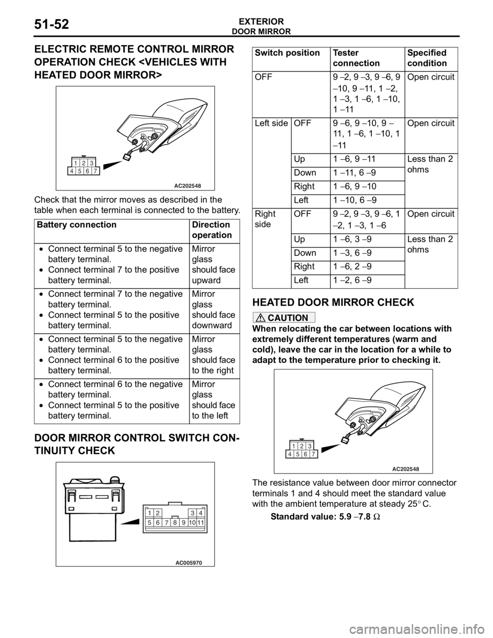
ELECTRIC REMOTE CONTROL MIRROR
OPERATION CHECK
AC202548
1
4567 23
Che
c k that th e mirror moves as describe d in the
t
a b l e when each terminal is conn ecte d to the batter y .
Battery connectionDirection
operation
•Connect terminal 5 to the negative
battery terminal.
•Connect terminal 7 to the positive
battery terminal.
Mirror
glass
should face
upward
•Connect terminal 7 to the negative
battery terminal.
•Connect terminal 5 to the positive
battery terminal.
Mirror
glass
should face
downward
•Connect terminal 5 to the negative
battery terminal.
•Connect terminal 6 to the positive
battery terminal.
Mirror
glass
should face
to the right
•Connect terminal 6 to the negative
battery terminal.
•Connect terminal 5 to the positive
battery terminal.
Mirror
glass
should face
to the left
DOOR MIRROR CONTROL SWITCH CON-
TINUITY CHECK
AC005970
2
14
3
510 9
8
7
6
11
Switch positionTester
connectionSpecified
condition
OFF9 − 2, 9 − 3, 9 − 6, 9
− 10, 9 − 11, 1 − 2,
1
− 3, 1 − 6, 1 − 10,
1
− 11
Open circuit
Left sideOFF9 − 6, 9 − 10, 9 −
11 , 1
− 6, 1 − 10, 1
− 11
Open circuit
Up1 − 6, 9 − 11Less than 2
ohms
Down1 − 11, 6 − 9
Right1 − 6, 9 − 10
Left1 − 10, 6 − 9
Right
sideOFF9 − 2, 9 − 3, 9 − 6, 1
− 2, 1 − 3, 1 − 6
Open circuit
Up1 − 6, 3 − 9Less than 2
ohms
Down1 − 3, 6 − 9
Right1 − 6, 2 − 9
Left1 − 2, 6 − 9
HEA T ED DOOR MIRROR CHECK
CAUTION
When relocating the car between locations with
extremely different temperatures (warm and
cold), leave the car in the location for a while to
adapt to the temperature prior to checking it.
AC202548
1
4567 23
The resistance value between door mirror connector
terminals 1 and 4 should meet the standard value
with the ambient temperature at steady 25
°C.
Standard value: 5.9 − 7.8 Ω
Page 385 of 800
52-1
GROUP 52
INTERIOR AND
SUPPLEMEN TAL
RESTRAINT
SYSTEM(SRS)
CONTENTS
INTERIOR . . . . . . . . . . . . . . . . . . . . . . . . . . . . . . . . . . . . . . . . . .52A
SUPPLEMENTAL RESTRAINT SYSTEM (SRS) . . . . . . . . . . . .52B
Page 386 of 800

NOTES
Page 387 of 800
54-1
GROUP 54
CHASSIS
ELECTRICAL
CONTENTS
CHASSIS ELECTRICAL . . . . . . . . . . . . . . . . . . . . . . . . . . . . . . .54A
SMART WIRING SYSTEM (SWS) NOT USING SWS
MONITOR . . . . . . . . . . . . . . . . . . . . . . . . . . . . . . . . . . . . . . . . . .54B
SMART WIRING SYSTEM (SWS) USING SWS MONITOR . . . .54C
Page 388 of 800

NOTES
Page 389 of 800
55-1
GROUP 55
HEATER, AIR
CONDITIONER AND
VENTIL ATION
CONTENTS
HEATER, AIR CONDITIONER AND VE NTILATION . . . . . . . . .55A
AUTOMATIC AIR CONDITIONER . . . . . . . . . . . . . . . . . . . . . . .55B
Page 390 of 800

NOTES