Cold start MITSUBISHI LANCER 2006 Workshop Manual
[x] Cancel search | Manufacturer: MITSUBISHI, Model Year: 2006, Model line: LANCER, Model: MITSUBISHI LANCER 2006Pages: 800, PDF Size: 45.03 MB
Page 36 of 800

AC200625
Cylinder block
drain plug
AC
ON-VEHICLE SER VICE
ENGINE COOLING14-22
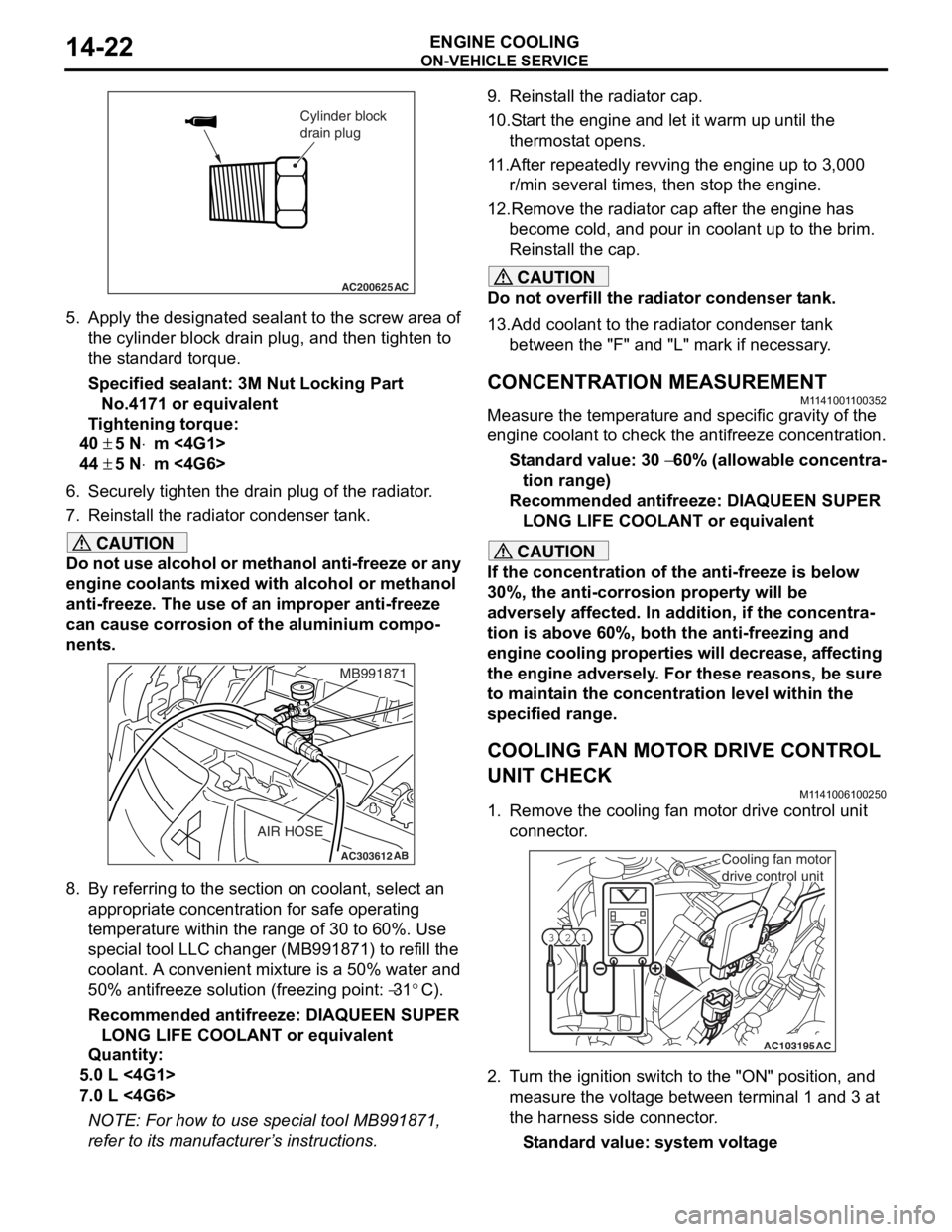
5.App l y the designa ted sealant to t he scre w area of
th e cylin der block drain plu g , and then tighten to
th e st and ard torq ue.
Sp e c ified s ealant: 3 M Nut Loc king Part
No. 4171 o r e quivale n t
Ti ghtenin g torque:
40 ± 5 N⋅m <4G1>
44 ± 5 N⋅m <4G6>
6.Securely tighten t he drain plug of t he radiator .
7.Reinst all the ra diato r con denser t ank.
CAUTION
Do not use alcohol or methanol anti-freeze or any
engine coolants mixed with alcohol or methanol
anti-freeze. The use of an improper anti-freeze
can cause corrosion of the aluminium compo
-
nents.
AC303612AB
MB991871
AIR HOSE
8. By referring to the section on coolant, select an
appropriate concentration for safe operating
temperature within the range of 30 to 60%. Use
special tool LLC changer (MB991871) to refill the
coolant. A convenient mixture is a 50% water and
50% antifreeze solution (freezing point:
−31°C).
Recommended antifreeze: DIAQUEEN SUPER LONG LIFE COOLANT or equivalent
Quantity:
5.0 L <4G1>
7.0 L <4G6>
NOTE: For how to use special tool MB991871,
refer to its manufacturer’s instructions.
9. Reinstall the radiator cap.
10.Start the engine and let it warm up until the thermostat opens.
11.After repeatedly revving the engine up to 3,000 r/min several times, then stop the engine.
12.Remove the radiator cap after the engine has become cold, and pour in coolant up to the brim.
Reinstall the cap.
CAUTION
Do not overfill the radiator condenser tank.
13.Add coolant to the radiator condenser tank between the "F" and "L" mark if necessary.
CONCENTRATION MEASUREMENT
M1141001100352
Measure the temperature and specific gravity of the
engine coolant to check the antifreeze concentration.
Standard value: 30 − 60% (allowable concentra-
tion range)
Recommended antifreeze: DIAQUEEN SUPER
LONG LIFE COOLANT or equivalent
CAUTION
If the concentration of the anti-freeze is below
30%, the anti-corrosion property will be
adversely affected. In addition, if the concentra
-
tion is above 60%, both the anti-freezing and
engine cooling properties will decrease, affecting
the engine adversely. For these reasons, be sure
to maintain the concentration level within the
specified range.
COOLING FAN MOTOR DRIVE CONTROL
UNIT CHECK
M1141006100250
1. Remove the cooling fan motor drive control unit connector.
AC103195
Y1716AU
1
23
AC
Cooling fan motor
drive control unit
2. Turn the ignition switch to the "ON" position, and
measure the voltage between terminal 1 and 3 at
the harness side connector.
Standard value: system voltage
Page 117 of 800

EMISSION CONTROL
ENGINE AND EMISSION CONTROL17-11
2. Plug the nipple from which the vacuum hose was removed.
3. When the engine is cold or hot, apply a vacuum of 53 kPa, and check the condition of the vacuum.
When engine is cold
(Engine coolant temperature: 40°C or less)
Engine conditionNormal condition
At idleVacuum is maintained.
3,000 r/min
When engine is hot
(Engine coolant temperature: 80°C or higher)
Engine conditionNormal condition
At idleVacuum is maintained.
3,000 r/min (within 3
minutes after engine
starts)Vacuum will leak.
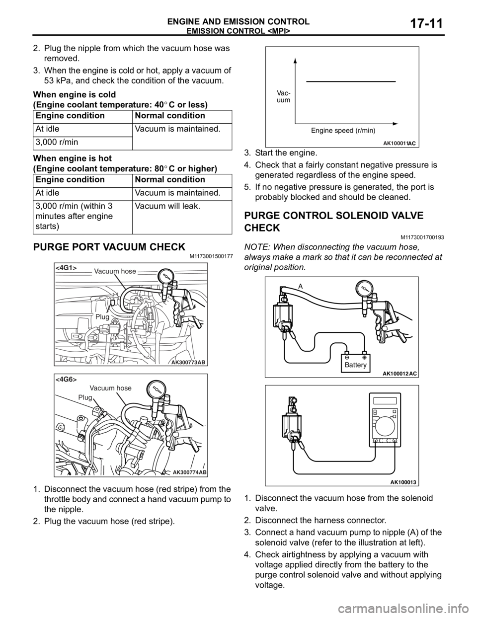
PURGE PORT VACUUM CHECKM1173001500177
AK300773
<4G1>
AB
Plug
Vacuum hose
AK300774
<4G6>
AB
Plug
Vacuum hose
1.Disco nnect th e vacuum ho se (red st ripe) from the
throttle body and connect a hand vacuum pump to
th e nip p le.
2.Plu g the vacuum hose (red stripe).
AK100011AC
Vac-
uum
Engine speed (r/min)
3.S t art the engine.
4.Check t hat a f a irly co nst ant n egative p r essure is
g enerate d regard l ess of the en gine spee d.
5.If no neg ative pressur e is genera t ed, th e port is
p r obably blocked an d sh ould be cleane d.
PURGE CONTROL SOLENOID VA L V E
CHECK
M1173 0017 0019 3
NOTE: Whe n discon nect i ng th e va cuum hose,
always make a mark so th at it can be reconnected at
original p o sition.
AK100012AC
Battery
A
AK100013
1.
Disco nnect the vacu um h o se f r om th e solenoid
valve.
2.Disco nnect the ha rness connector .
3.Con nect a ha nd vacu um pump to nipp le (A) of the
solen o id valve (ref e r to th e ill ust r ation at le f t ).
4.Check a i rtig htness b y app lying a vacuum with
volt age applied d i rectly from t he batt e ry to the
p u rge con t rol so leno id valve an d without app lying
volt age .