Compressor MITSUBISHI LANCER 2006 Workshop Manual
[x] Cancel search | Manufacturer: MITSUBISHI, Model Year: 2006, Model line: LANCER, Model: MITSUBISHI LANCER 2006Pages: 800, PDF Size: 45.03 MB
Page 104 of 800
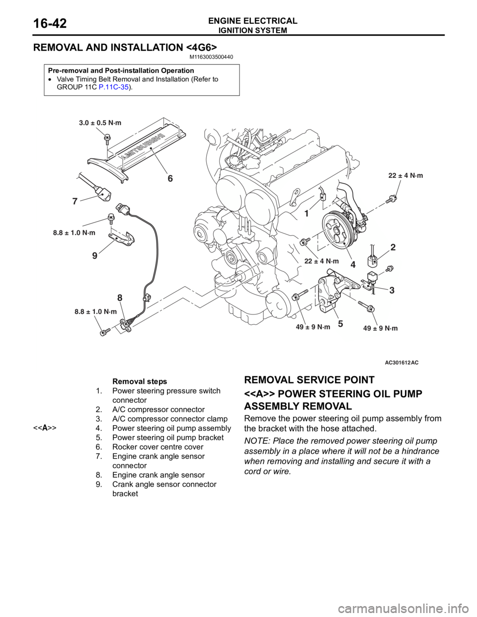
IGNITION SYSTEM
ENGINE ELECTRICAL16-42
REMOVAL AND INSTALLATION <4G6>
M1163003500440
Pre-removal and Post-installation Operation
•Valve Timing Belt Removal and Installation (Refer to
GROUP 11C P.11C-35).
AC301612
8.8 ± 1.0 N·m
8
8.8 ± 1.0 N·m
9
1
22 ± 4 N·m
4
2
3
49 ± 9 N·m49 ± 9 N·m5
22 ± 4 N·m
3.0 ± 0.5 N·m
6
7
AC
Removal steps
1.Power steering pressure switch
connector
2.A/C compressor connector
3.A/C compressor connector clamp
<>4.Power steering oil pump assembly
5.Power steering oil pump bracket
6.Rocker cover centre cover
7.Engine crank angle sensor
connector
8.Engine crank angle sensor
9.Crank angle sensor connector
bracket
REMOV A L SER VICE POINT
<> POWE R STEERING OIL PUMP
ASSEMBL
Y REMOV A L
Remove the p o wer st eering oil pump assembly from
the bra
cke t with th e hose att a ched.
NOTE: Place the remo ved power st eering oil pump
assembly in a place where it will not be a hindrance
wh
en removing an d inst a lling an d secure it with a
cord or wire.
Page 186 of 800
SPECIAL TOOLS
FRONT SUSPENSION33-4
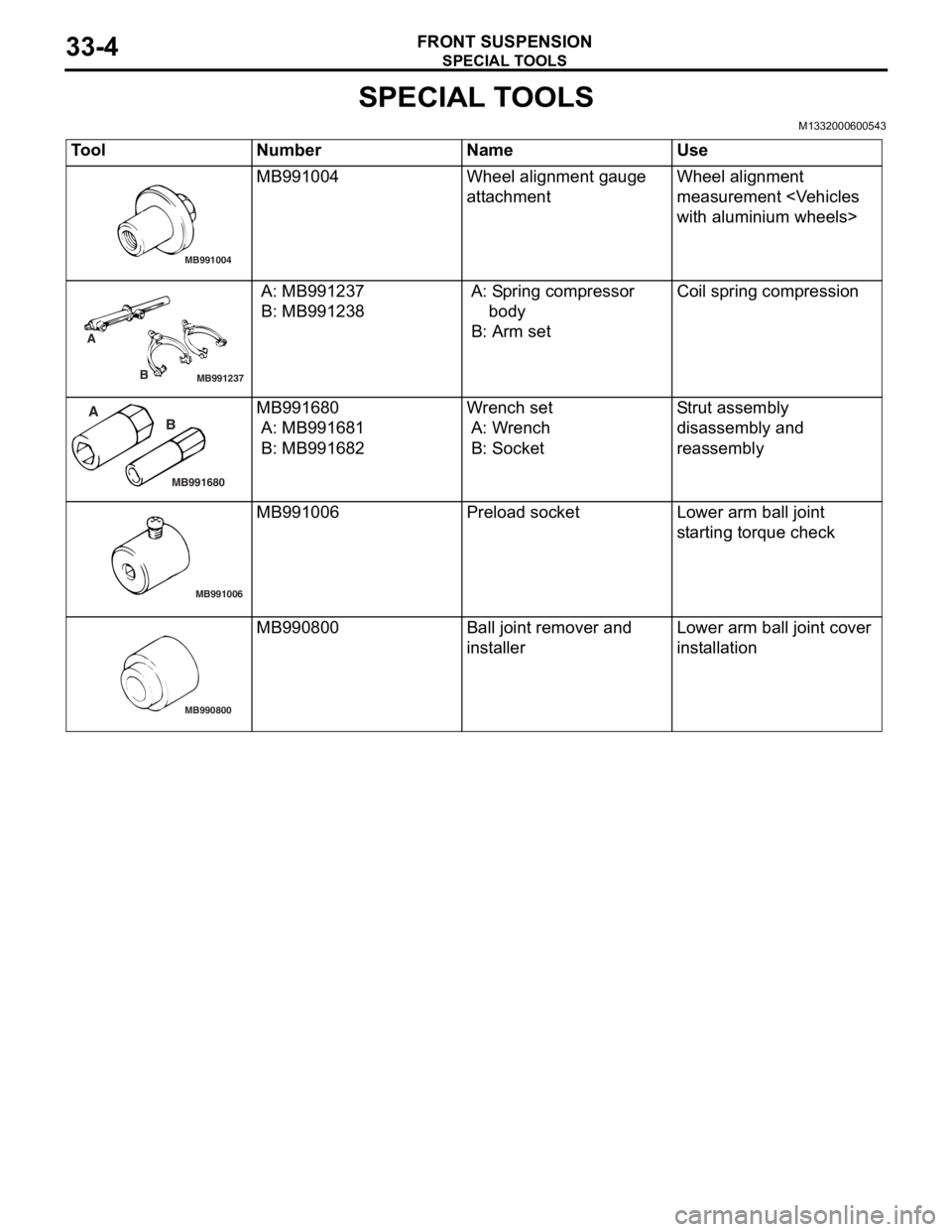
SPECIAL TOOLS
M1332000600543
ToolNumberNameUse
MB991004
MB991004Wheel alignme n t gau ge
att
a chmentWheel alig nme n t
measurement
with aluminium wheels>
MB991237
A
B
A: MB9912 37
B: MB991238
A: Sp ring compressor
b ody
B: Arm set
Coil spring compression
MB991680
A BMB991680
A: MB9916 81
B: MB991682
Wr ench set
A: W r ench
B: Socket
Str u t a s s e m b l y
d
i sa ssembly an d
reassembly
MB991006
MB991006Prel oad socketLo wer arm ball joint
st
arting torque check
MB990800
MB990800Ball j o int remo ver an d
inst
al lerLo wer arm ball joint cover
inst
allation
Page 191 of 800
Page 192 of 800
STRUT ASSEMBLY
FRONT SUSPENSION33-10
>>B<< STRUT NUT (SELF-LOCKING NUT)
INSTALLATION
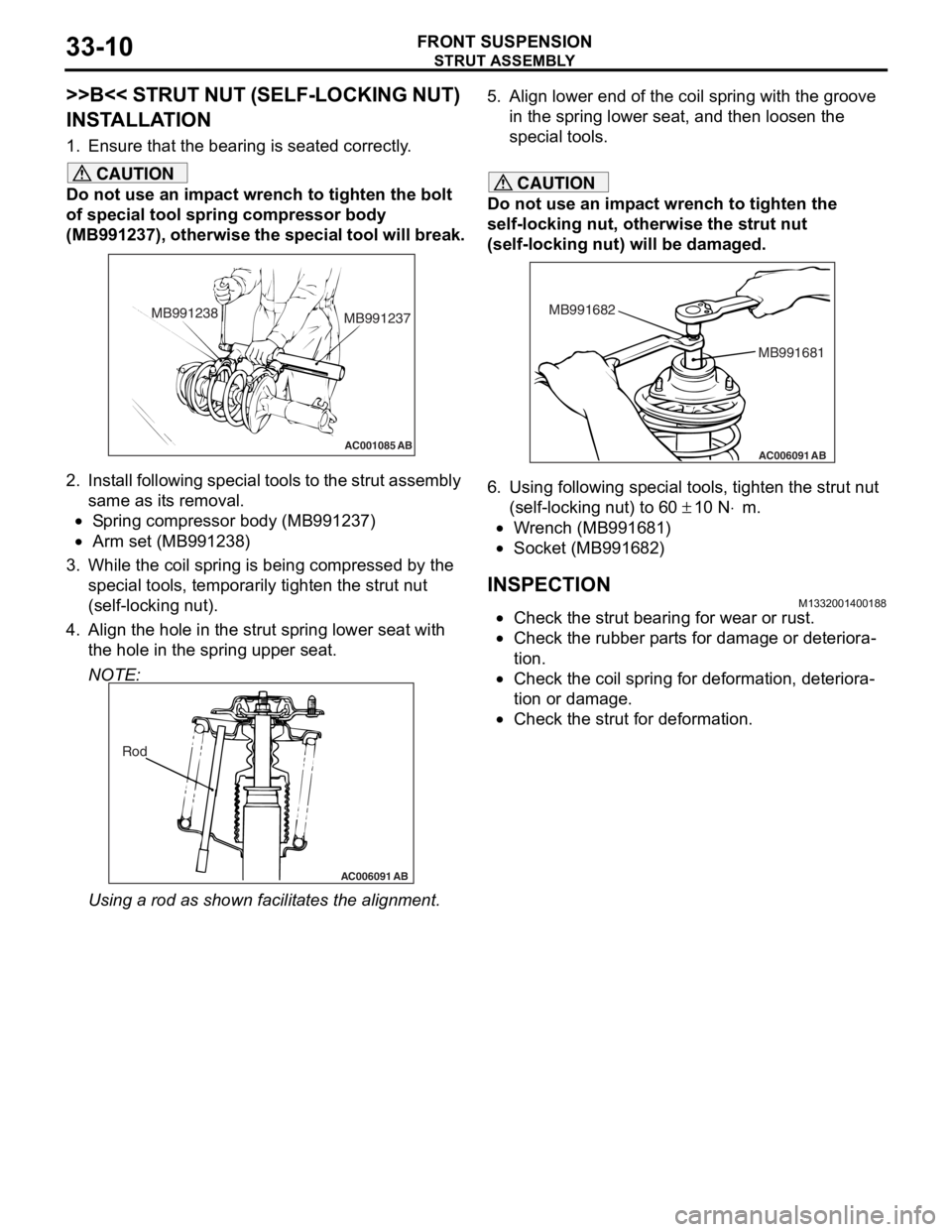
1. Ensure that the bearing is seated correctly.
CAUTION
Do not use an impact wrench to tighten the bolt
of special tool spring compressor body
(MB991237), otherwise the special tool will break.
AC001085 AB
MB991238MB991237
2. Install following special tools to the strut assembly
same as its removal.
•Spring compressor body (MB991237)
•Arm set (MB991238)
3. While the coil spring is being compressed by the
special tools, temporarily tighten the strut nut
(self-locking nut).
4. Align the hole in the strut spring lower seat with the hole in the spring upper seat.
NOTE:
AC006091 AB
Rod
Using a rod as shown fa cilitates the alignment.
5. Align lower end of the coil spring with the groove
in the spring lower seat, and then loosen the
special tools.
CAUTION
Do not use an impact wrench to tighten the
self-locking nut, otherwise the strut nut
(self-locking nut) will be damaged.
AC006091 AB
MB991681
MB991682
6. Using following special tools, tighten the strut nut
(self-locking nut) to 60
± 10 N⋅m.
•Wrench (MB991681)
•Socket (MB991682)
INSPECTIONM1332001400188
•Check the strut bearing for wear or rust.
•Check the rubber parts for damage or deteriora-
tion.
•Check the coil spring for deformation, deteriora-
tion or damage.
•Check the strut for deformation.
Page 203 of 800
MB990947
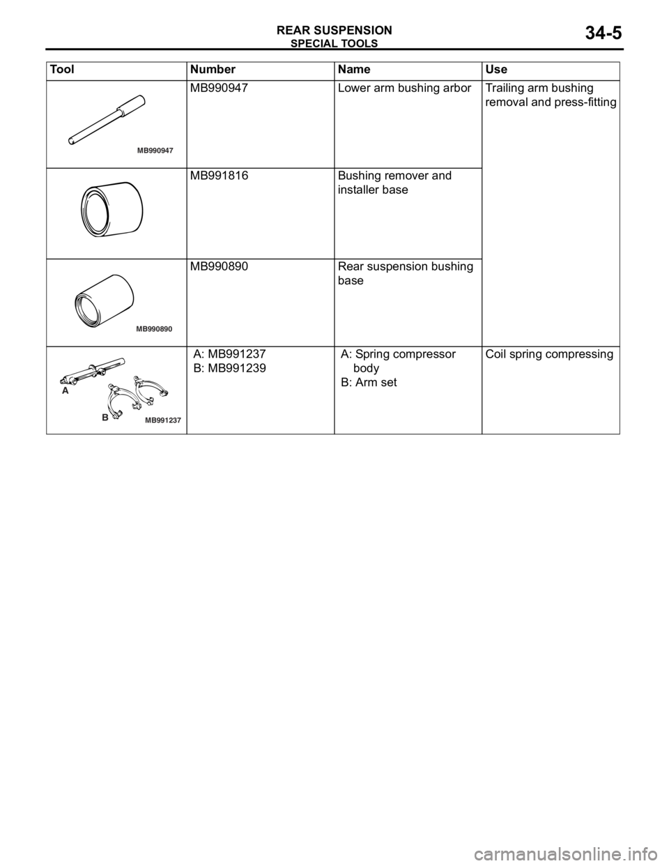
SPECIA L T OOLS
REAR SU SPENS I ON34-5
MB990947Lower arm bushing arborTr a iling arm bushing
re
moval and press-fit t ing
MB991816Bushing remove r and
inst
al ler b a se
MB990890
MB990890Rear suspension bushing
base
MB991237
A
B
A: MB9912 37
B: MB991239
A: Sp ring compressor
bo dy
B: Arm set
Coil spring compressing
Tool Nu mber Na me Use
Page 214 of 800
SHOCK ABSORBER ASSEMBLY
REAR SUSPENSION34-16
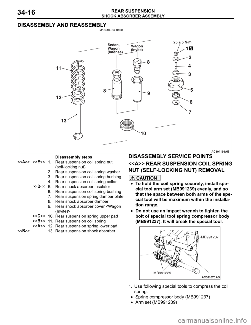
DISASSEMBLY AND REASSEMBLY
M1341005300460
AC304156AE
25 ± 5 N·m
1
2
4
5
3
6
7
8
9
11
13
12
10
8
Wagon
(Invite)
Sedan,
Wagon
(Intense)
Disassembly steps
<>>>E<<1.Rear suspension coil spring nut
(self-locking nut)
2.Rear suspension coil spring washer
3.Rear suspension coil spring bushing
4.Rear suspension coil spring collar
>>D<<5.Rear shock absorber insulator
6.Rear suspension coil spring bushing
7.Rear suspension spring damper plate
8.Rear shock absorber damper
9.Rear shock absorber cover
>>C<<10.Rear suspension spring upper pad
>>B<<11 .Rear suspension coil spring
>>A<<12.Rear suspension spring lower pad
<>13.Rear suspension shock absorber
DISASSEMBL
Y SER V ICE POINTS
<> REAR SUSPENSION COIL SPRING
NUT (SELF-LOCKING NUT) REMOV
A L
CAUTION
•To hold the coil spring securely, install spe-
cial tool arm set (MB991239) evenly, and so
that the space between both arms of the spe
-
cial tool will be maximum within the installa-
tion range.
•
AC001070
MB991237
MB991239
AB
Do not use an impact wrench to tighten the
bolt of special tool spring compressor body
(MB991237). It will break the special tool.
1. Use following special tools to compress the coil spring.
•Spring compressor body (MB991237)
•Arm set (MB991239)
Page 215 of 800
SHOCK ABSORBER ASSEMBLY
REAR SUSPENSION34-17
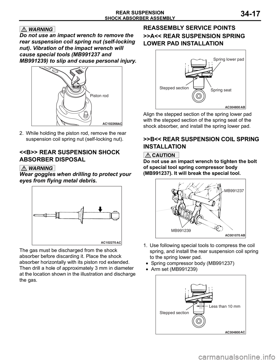
WARNING
Do not use an impact wrench to remove the
rear suspension coil spring nut (self-locking
nut). Vibration of the impact wrench will
cause special t ools (MB991237 and
MB991239) to slip and cause personal injury.
AC102268AC
Piston rod
2. While holding the piston rod, remove the rear
suspension coil spring nut (self-locking nut).
<> REAR SUSPENSION SHOCK
ABSORBER DISPOSAL
WARNING
Wear goggles when dril ling to protect your
eyes from flying metal debris.
AC102270
AC
The gas must be discharged from the shock
absorber before discarding it. Place the shock
absorber horizontally with its piston rod extended.
Then drill a hole of approximately 3 mm in diameter
at the location shown in the illustration and discharge
the gas.
REASSEMBLY SERVICE POINTS
>>A<< REAR SUSPENSION SPRING
LOWER PAD INSTALLATION
AC304800AB
Spring lower pad
Stepped section
Spring seat
Align the stepped section of the spring lower pad
with the stepped section of the spring seat of the
shock absorber, and install the spring lower pad.
>>B<< REAR SUSPENSION COIL SPRING
INSTALLATION
CAUTION
Do not use an impact wrench to tighten the bolt
of special tool spring compressor body
(MB991237). It will break the special tool.
AC001070
MB991237
MB991239
AB
1. Use following special tools to compress the coil spring, and install the rear suspension coil spring
to the spring lower pad.
•Spring compressor body (MB991237)
•
AC304800AC
Less than 10 mm
Stepped section
Arm set (MB991239)
Page 266 of 800
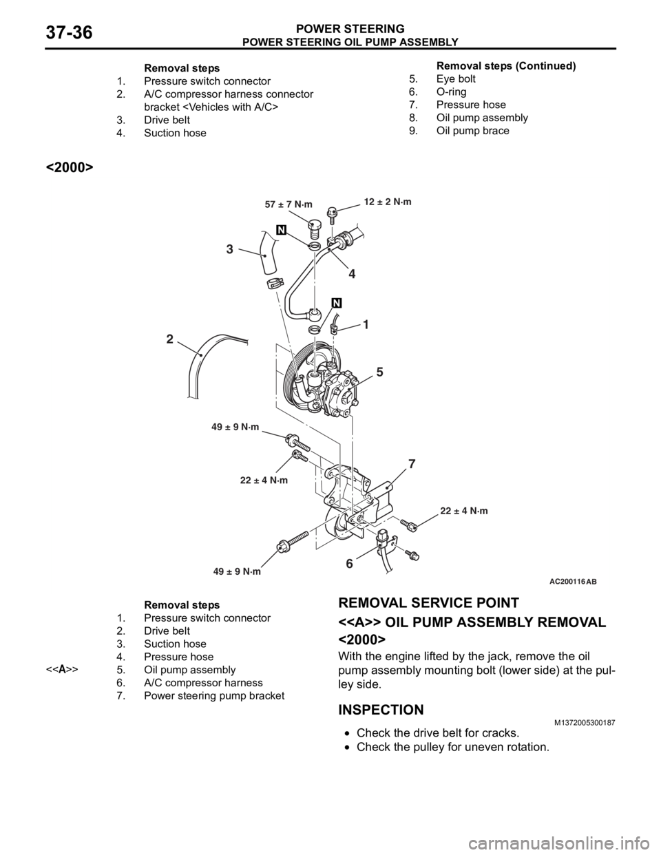
Removal steps
1.Pressure switch connector
2.A/C compressor harness connector
bracket
3.Drive belt
4.Suction hose
5.Eye bolt
6.O-ring
7.Pressure hose
8.Oil pump assembly
9.Oil pump brace
POWER STEERING OIL PUMP ASSEMBLY
POWER STEERING37-36
<2000>
AC200116AB
22 ± 4 N·m
12 ± 2 N·m
22 ± 4 N·m
49 ± 9 N·m 57 ± 7 N·m
1
5
4
3
6
2
7
49 ± 9 N·m
Removal steps
1.Pressure switch connector
2.Drive belt
3.Suction hose
4.Pressure hose
<>5.Oil pump assembly
6.A/C compressor harness
7.Power steering pump bracket
REMOVA L SER VICE POINT
<> OIL PUMP ASSEMBL Y REMOV A L
<2000>
With the eng ine lif t ed by the jack, remove the o il
pump
assembly mounting b o lt (lower side) a t the pul
-
ley side .
INSPECTIONM13720053 0018 7
•Check the drive belt for cracks.
•Check th e pulley for une ven r o t a tion.
Remova l st ep s ( C ont inu e d)
Page 395 of 800
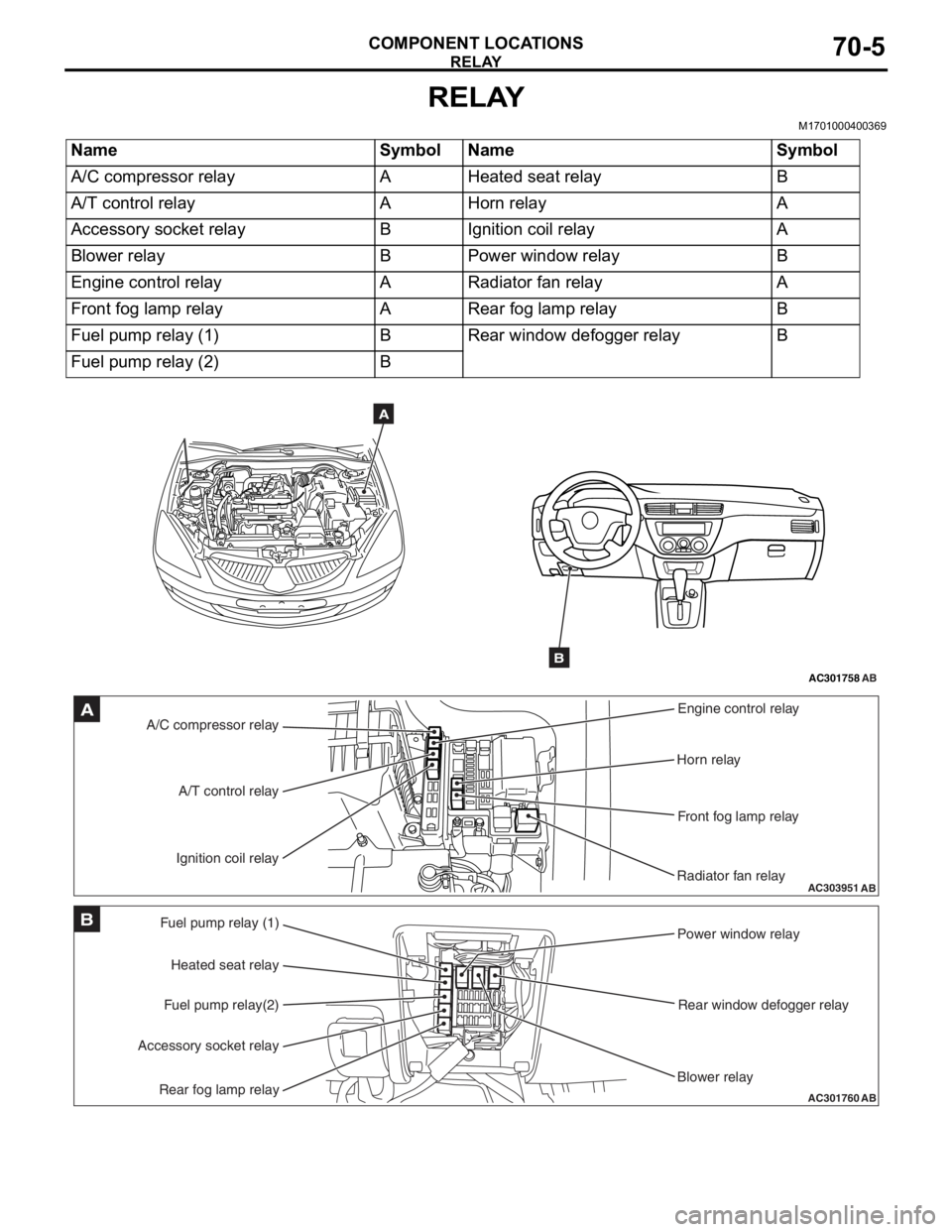
RELAY
COMPONENT LOCATIONS70-5
RELAY
M1701000400369
NameSymbolNameSymbol
A/C compressor relayAHeated seat relayB
A/T control relayAHorn relayA
Accessory socket relayBIgnition coil relayA
Blower relayBPower window relayB
Engine control relayARadiator fan relayA
Front fog lamp relayARear fog lamp relayB
Fuel pump relay (1)BRear window defogger relayB
Fuel pump relay (2)B
AC301758AB
A
B
AC303951AB
A/C compressor relayEngine control relay
Horn relay
Front fog lamp relay
Radiator fan relay
A/T control relay
Ignition coil relayA
AC301760
Fuel pump relay (1) Power window relay
Rear window defogger relay
Blower relay
Heated seat relay
Fuel pump relay(2)
Accessory socket relay
Rear fog lamp relayAB
B
Page 420 of 800
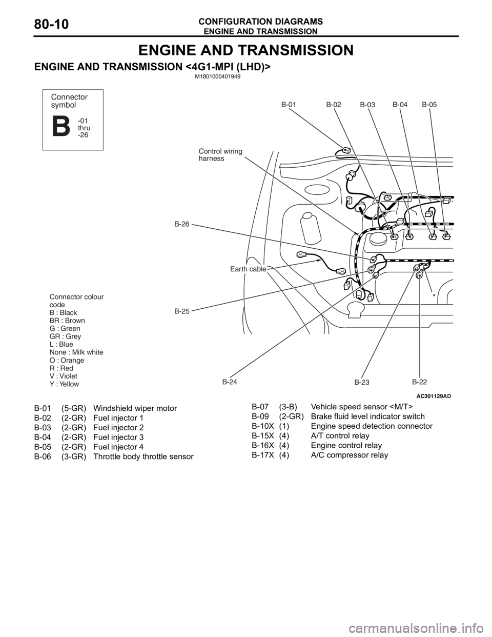
ENGINE AND TRANSMISSION
CONFIGURATION DIAGRAMS80-10
ENGINE AND TRANSMISSION
ENGINE AND TRANSMISSION <4G1-MPI (LHD)>M1801000401949
AC301129
AD
B-02
B-03B-04B-05
B-22
B-23
B-24
B-25
B-26
Control wiring
harnessB-01
Connector colour
code
B : Black
BR : Brown
G : Green
GR : Grey
L : Blue
None : Milk white
O : Orange
R : Red
V : Violet
Y : Yellow*
Connector
symbol
-01
thru
-26
B
Earth cable
B-01(5-GR)Windshield wiper motor
B-02(2-GR)Fuel injector 1
B-03(2-GR)Fuel injector 2
B-04(2-GR)Fuel injector 3
B-05(2-GR)Fuel injector 4
B-06(3-GR)Throttle body throttle sensor
B-07(3-B)Vehicle speed sensor
B-09(2-GR)Brake fluid level indicator switch
B-10X(1)Engine speed detection connector
B-15X(4)A/T control relay
B-16X(4)Engine control relay
B-17X(4)A/C compressor relay