Fender MITSUBISHI LANCER 2006 Workshop Manual
[x] Cancel search | Manufacturer: MITSUBISHI, Model Year: 2006, Model line: LANCER, Model: MITSUBISHI LANCER 2006Pages: 800, PDF Size: 45.03 MB
Page 273 of 800
42-1
GROUP 42
BODY
CONTENTS
HOOD . . . . . . . . . . . . . . . . . . . . .42-3
ON-VEHICLE SERVICE. . . . . . . . .42-3
ADJUSTMENT OF CLEARANCE
AROUND HOOD . . . . . . . . . . . . . . . . . . 42-3
ADJUSTMENT OF ALIGNMENT OF
HOOD STEPPED PORTION AND
HOOD STRIKER . . . . . . . . . . . . . . . . . . 42-3
ADJUSTMENT OF HOOD HEIGHT . . . 42-3
HOOD . . . . . . . . . . . . . . . . . . . . . . .42-4
REMOVAL AND INSTALLATION . . . . . 42-4
FENDER . . . . . . . . . . . . . . . . . . .42-5
SPECIAL TOOL . . . . . . . . . . . . . . .42-5
FENDER . . . . . . . . . . . . . . . . . . . . .42-6
REMOVAL AND INSTALLATION . . . . . 42-6
FUEL FILLER LID . . . . . . . . . . .42-8
REMOVAL AND INSTALLATION .42-8
STRUT TOWER BAR . . . . . . . .42-9
REMOVAL AND INSTALLATION .42-9
WINDOW GLASS . . . . . . . . . . . 42-10
ADHESIVE . . . . . . . . . . . . . . . . . . .42-10
SPECIAL TOOLS . . . . . . . . . . . . . .42-10
WINDOW REPAIR . . . . . . . . . . . . .42-10
WINDSHIELD . . . . . . . . . . . . . . . . .42-12
REMOVAL AND INSTALLATION . . . . . . 42-12
REAR WINDOW GLASS
REMOVAL AND INSTALLATION . . . . . . 42-17
QUARTER WINDOW GLASS
REMOVAL AND INSTALLATION . . . . . . 42-20
TAILGATE WINDOW GLASS
REMOVAL AND INSTALLATION . . . . . . 42-23
DOOR . . . . . . . . . . . . . . . . . . . . 42-25
SERVICE SPECIFICA TIONS . . . . .42-25
SEALANT . . . . . . . . . . . . . . . . . . . .42-25
SPECIAL TOOLS . . . . . . . . . . . . . .42-26
Continued on next page
Page 277 of 800
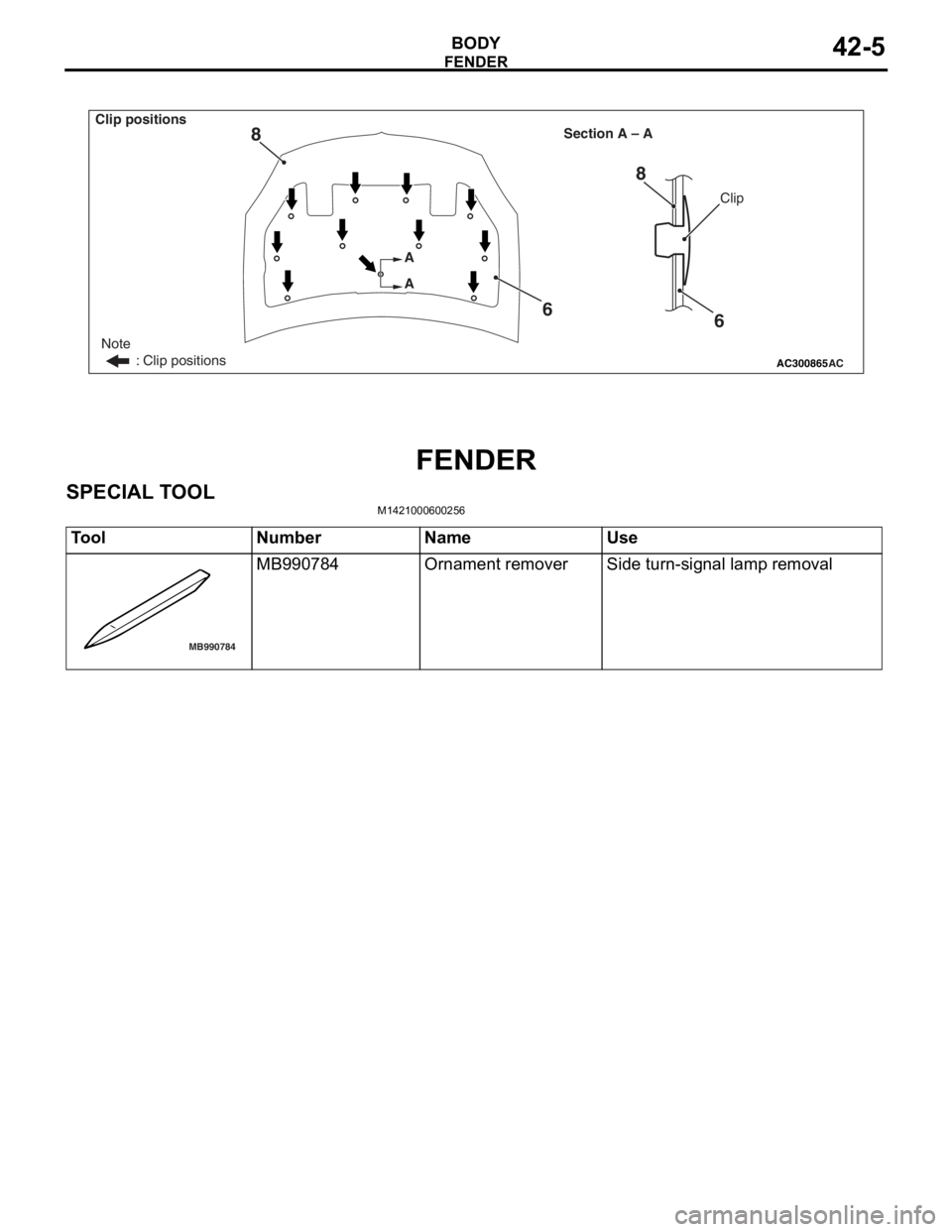
AC300865
Note
: Clip positions
Section A – A
AC
Clip
A
A
6
8
6
8
Clip positions
FEN
D ER
BOD Y42-5
FENDER
SPECIAL T O OL
M14210006 0025 6
ToolNumberNameUse
MB990784
MB990784Ornament removerSide turn-signal lamp removal
Page 278 of 800
FENDER
BODY42-6
FENDER
REMOVAL AND INSTALLATION
M1421001900302
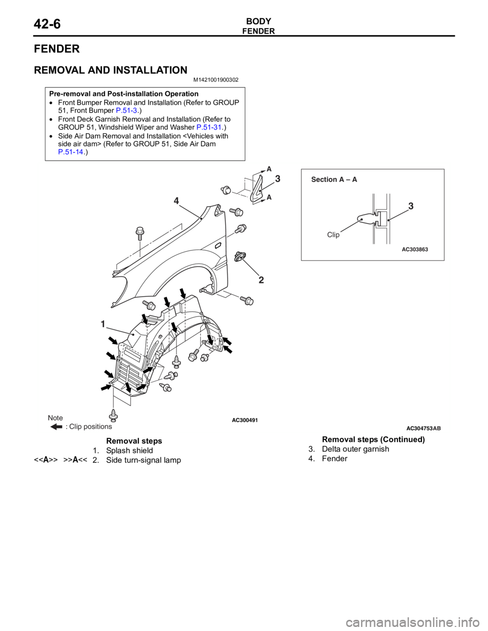
Pre-removal and Post-installation Operation
•Front Bumper Removal and Installation (Refer to GROUP
51, Front Bumper P.51-3.)
•Front Deck Garnish Removal and Installation (Refer to
GROUP 51, Windshield Wiper and Washer P.51-31.)
•Side Air Dam Removal and Installation
P.51-14.)
AC300491AC304753
AC303863
Clip
Section A – A
AB
A A
1
23
3
4
Note
: Clip positions
Removal steps
1.Splash shield
<>>>A<<2.Side turn-signal lamp
3.Delta outer garnish
4.Fender
Removal steps (Continued)
Page 279 of 800
Page 299 of 800
DOOR
BODY42-27
ON-VEHICLE SERVICE
DOOR FIT ADJUSTMENT
M1423001100175
CAUTION
•Attach protection tape to the fender and door
edges where the hinge is installed.
•Do not rotate special tool door adjusting
wrench (MB991164) with a torque of over 98
N
⋅m
AC000592
MB990900
or
MB991164
AB
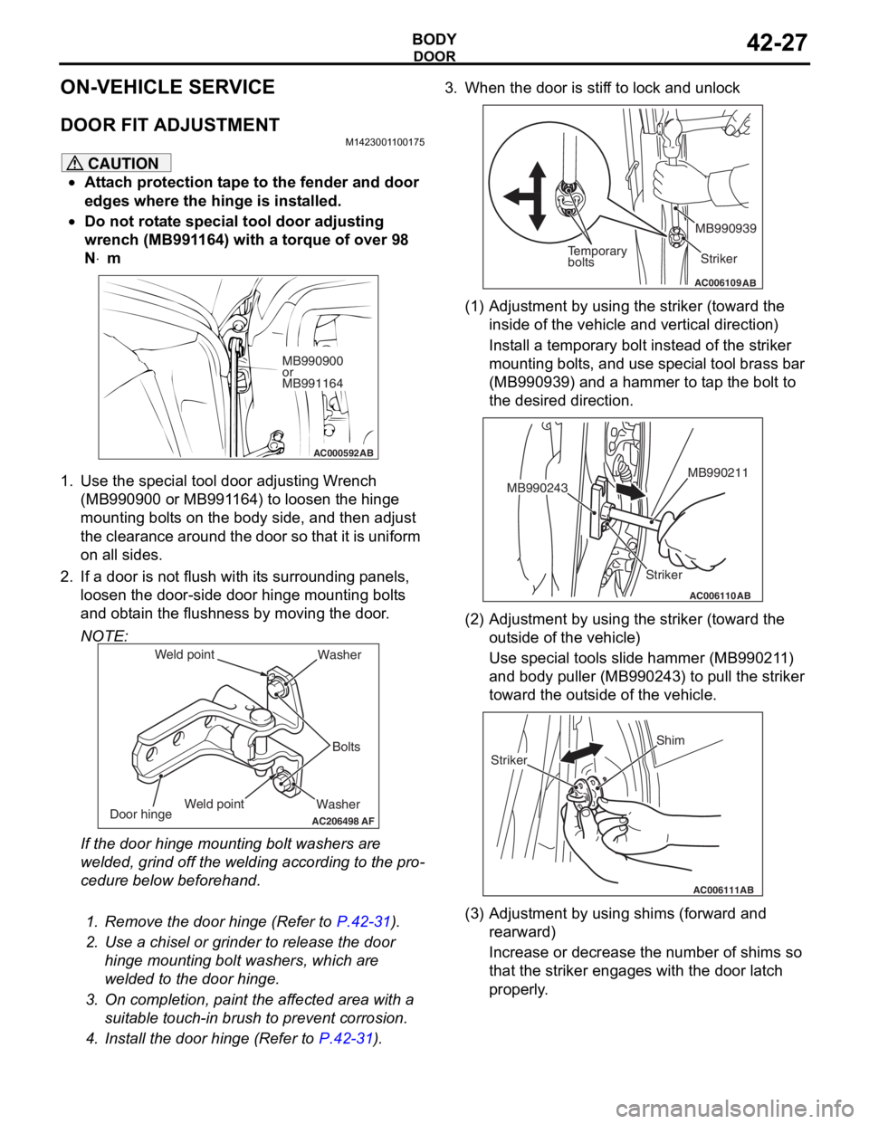
1. Use the special tool door adjusting Wrench (MB990900 or MB991164) to loosen the hinge
mounting bolts on the body side, and then adjust
the clearance around the door so that it is uniform
on all sides.
2. If a door is not flush with its surrounding panels,
loosen the door-side d oor hinge mounting bolts
and obtain the flushness by moving the door.
NOTE:
AC206498
Washer Bolts
Washer
Door hinge
AF
Weld point
Weld point
If the door hinge mounting bolt washers are
welded, grind off the welding according to the pro
-
cedure below beforehand.
.
1. Remove the door hinge (Refer to P.42-31).
2. Use a chisel or grinder to release the door
hinge mounting bolt washers, which are
welded to the door hinge.
3. On completion, paint the affected area with a suitable touch-in brush to prevent corrosion.
4. Install the door hinge (Refer to P.42-31).
3. When the door is stiff to lock and unlock
AC006109AB
Temporary
bolts Striker
MB990939
(1) Adjustment by using the striker (toward the
inside of the vehicle and vertical direction)
Install a temporary bolt instead of the striker
mounting bolts, and use special tool brass bar
(MB990939) and a hammer to tap the bolt to
the desired direction.
AC006110
Striker MB990211
MB990243
AB
(2) Adjustment by using the striker (toward the
outside of the vehicle)
Use special tools slide hammer (MB990211)
and body puller (MB990243) to pull the striker
toward the outside of the vehicle.
AC006111AB
Shim
Striker
(3) Adjustment by using shims (forward and rearward)
Increase or decrease the number of shims so
that the striker engages with the door latch
properly.
Page 341 of 800
MOULDINGS
EXTERIOR51-9
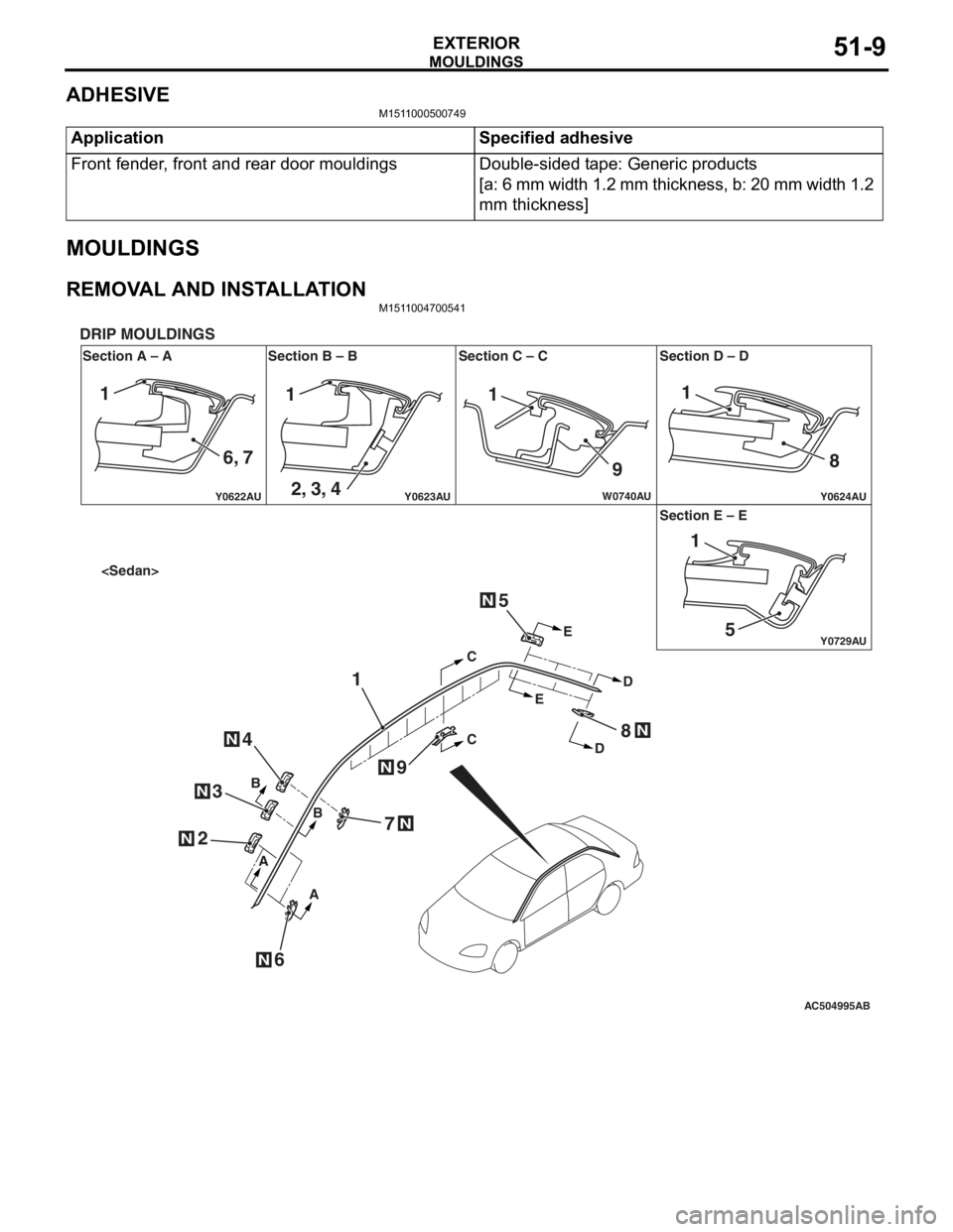
ADHESIVE
M1511000500749
ApplicationSpecified adhesive
Front fender, front and rear door mouldingsDouble-sided tape: Generic products
[a: 6 mm width 1.2 mm thickness, b: 20 mm width 1.2
mm thickness]
MOULDINGS
REMOVAL AND INSTALLATIONM1511004700541
AC504995
Y0622AU
Y0624AUY0623AU
Y0729AU
W0740AU
Section A – A
DRIP MOULDINGS
Section B – B Section C – C Section D – D
Section E – E
AB
N
N
N
N
N
CC
E E
D
D
B
B
A
A
1
2
6
4
3
5
7
8
9
N
N
N
111
9 8
51
1
6, 7 2, 3, 4
Page 344 of 800
AC504986 AC400117
AC400128
Section A – A
DOOR MOULDINGS
Section B – B Section C – C
AB
AA C
C
BB2
1
3
ClipClip
Boss
AC400840AE
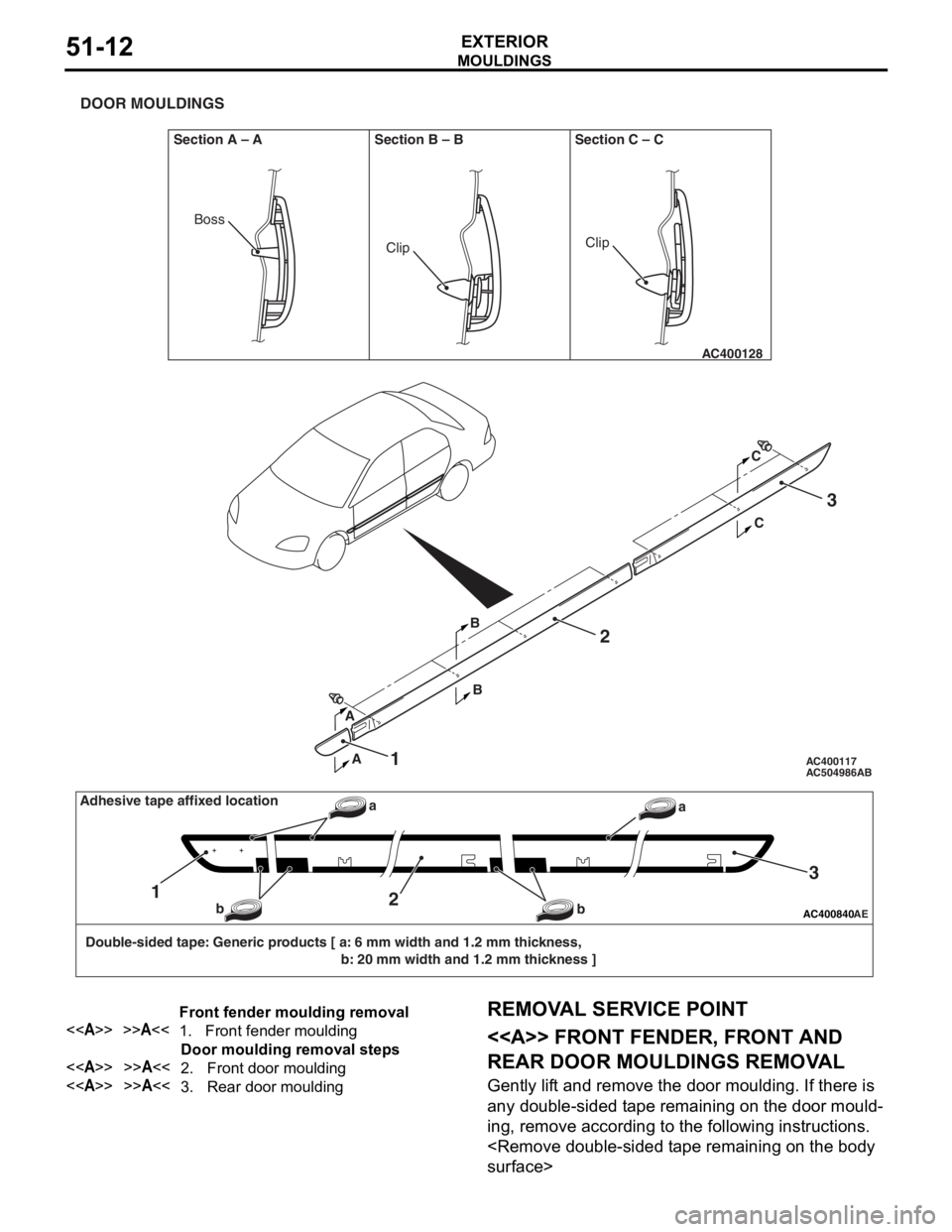
Double-sided tape: Generic products [ a: 6 mm width and 1.2 mm thickness, b: 20 mm width and 1.2 mm thickness ]
12
3
a
b
baAdhesive tape affixed location
Front fender moulding removal
<>>>A<<1.Front fender moulding
Door moulding removal steps
<>>>A<<2.Front door moulding
<>>>A<<3.Rear door moulding
MO
UL DI N G S
EXTERIOR51-12
REMOVA L SER VICE POINT
<> FRONT FENDER, FRONT AND
REAR DOOR MOULDINGS REMOV
A L
Gently lif t and remo ve th e door moulding . If the r e is
any d
ouble-sided t ape remainin g on th e door mould
-
ing, remove accord ing to the fo llowing in struction s .
Page 345 of 800
AC000420Double-sided tapeProtection tapeAB
MO
UL DI N G S
EXTERIOR51-13
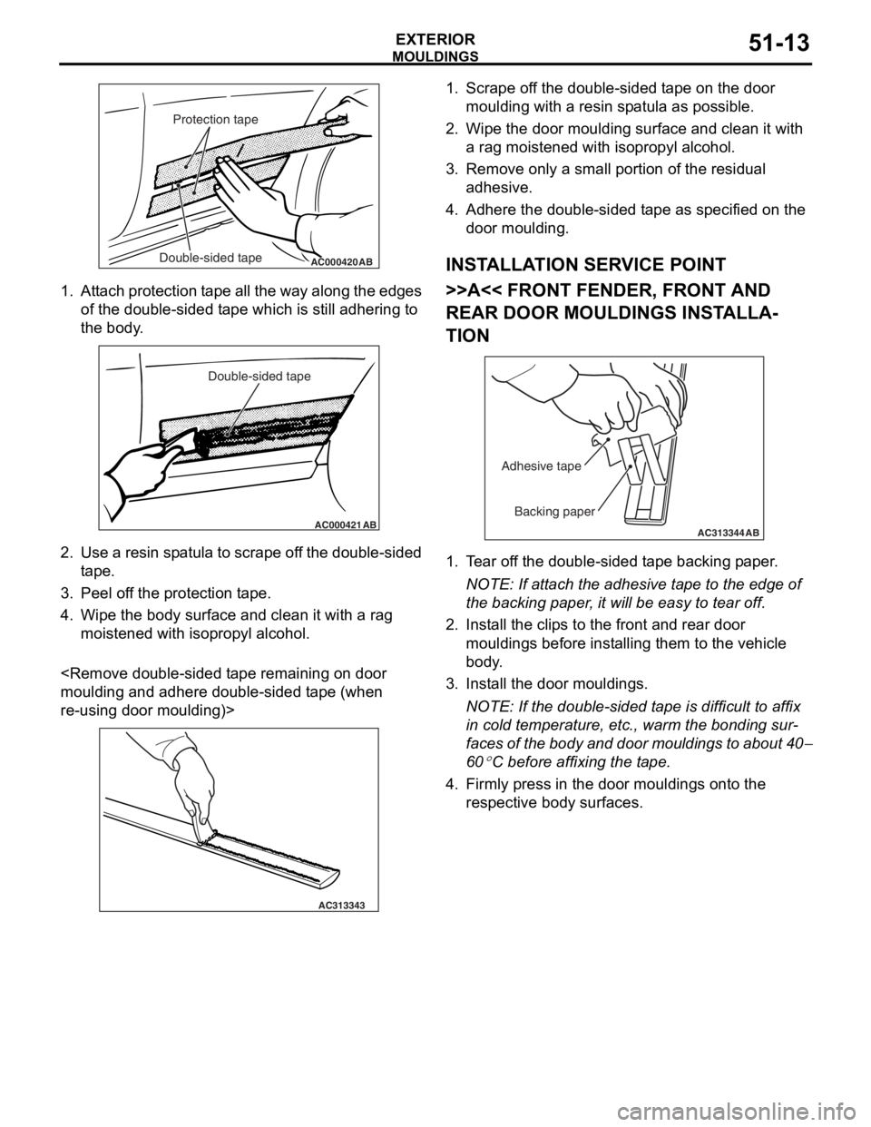
1.At t a ch pro t ection t a pe all th e wa y alon g the e dge s
of the do uble - sid ed t ape which is still adh ering to
th e body .
AC000421
Double-sided tape
AB
2.Use a resin sp atula to scrape of f t he dou ble-sided
t ape .
3.Pee l of f the pr otect i on t ape .
4.Wipe th e body su rface and clean it with a rag
moistened with isopro p yl alcohol.
and a dhere d ouble-sided t ape (wh en
re-using do
or mo ulding)>
AC313343
1.Scrape o f f the double-sided t ape on th e door
moulding with a re sin sp atula as possible.
2.Wipe th e door moulding surfa c e a nd clean it with
a rag moistened with isoprop yl a l co hol.
3.Remove only a small po rtion o f the re sid ual
a dhesive .
4.Adh e re the double-sided t ape as specified on t he
d oor mo ulding.
INSTALLA T ION SER VICE POINT
>>A<< FRONT FENDER, FRONT AND
REAR DOOR MOULDINGS INST
ALLA
-
TION
AC313344
Backing paper
Adhesive tape
AB
1.
T ear of f the double-sided t ape backing p aper .
NOTE: If atta ch the adhesive t a pe to the edg e of
th
e backing p aper , it will be easy to te ar off.
2.In st all the clip s to the front a nd rear door
mouldings befo r e inst alling th em to the vehicle
b ody .
3.In st all the do or mo uldings.
NOTE: If the double-sided t ape is difficult to af fix
in co
ld te mpera t ure, et c., warm the b ondin g su r
-
faces of the bod y and doo r mo uldin g s to ab out 40−
60
°C bef ore affixing the t a p e .
4.Firmly pre ss in the door moulding s ont o the
re spective bod y surface s .
Page 364 of 800
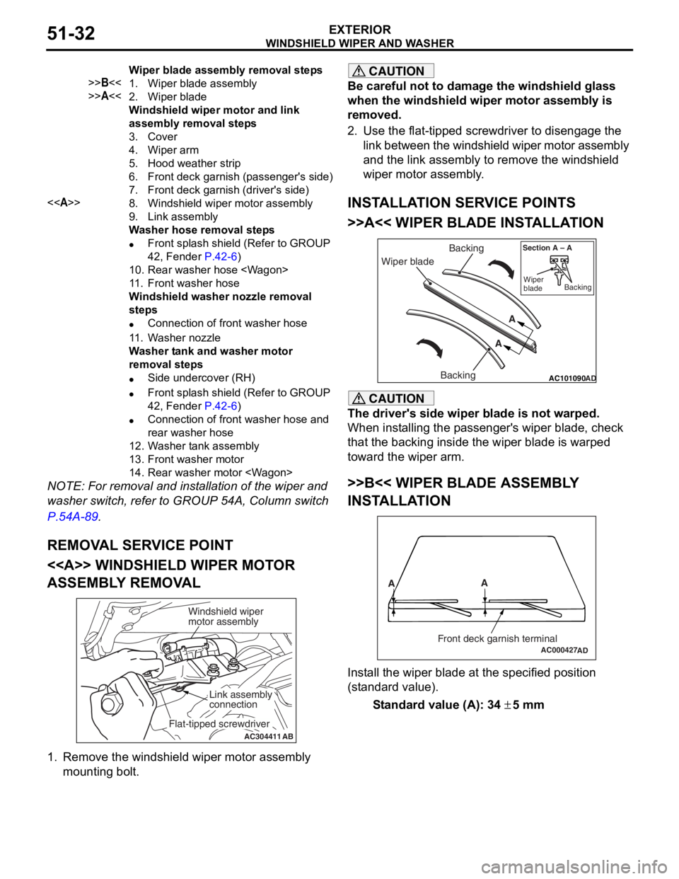
Wiper blade assembly removal steps
>>B<<1.Wiper blade assembly
>>A<<2.Wiper blade
Windshield wiper motor and link
assembly removal steps
3.Cover
4.Wiper arm
5.Hood weather strip
6.Front deck garnish (passenger's side)
7.Front deck garnish (driver's side)
<>8.Windshield wiper motor assembly
9.Link assembly
Washer hose removal steps
•Front splash shield (Refer to GROUP
42, Fender
P.42-6)
10.Rear washer hose
11 .Front washer hose
Windshield washer nozzle removal
steps
•Connection of front washer hose
11 .Washer nozzle
Washer tank and washer motor
removal steps
•Side undercover (RH)
•Front splash shield (Refer to GROUP
42, Fender
P.42-6)
•Connection of front washer hose and
rear washer hose
12.Washer tank assembly
13.Front washer motor
14.Rear washer motor
WINDSHIELD W I PER AND W A SHER
EXTERIOR51-32
NOTE: For re moval a nd in st allation of the wiper an d
washer switch, refer to GROUP 54A, Colu mn switch
P.5 4 A - 89.
REMOV A L SER V ICE POINT
<> WI NDSHIELD W I PER MOT O R
ASSEMBL
Y REMOV A L
AC304411AB
Windshield wiper
motor assembly
Link assembly
connection
Flat-tipped screwdriver
1.
Remove the win d shield wiper motor asse mbly
mounting bo lt.
CAUTION
Be careful not to damage the windshield glass
when the windshield wiper motor assembly is
removed.
2. Use the flat-tipped screwdriver to disengage the link between the windshield wiper motor assembly
and the link assembly to remove the windshield
wiper motor assembly.
INSTALLATION SERVICE POINTS
>>A<< WIPER BLADE INSTALLATION
AC101090 AD
Wiper blade Backing
Backing A
A
Section A – A
Wiper
blade Backing
CAUTION
The driver's side wiper blade is not warped.
When installing the passenger's wiper blade, check
that the backing inside the wiper blade is warped
toward the wiper arm.
>>B<< WIPER BLADE ASSEMBLY
INSTALLATION
AC000427
A
A
Front deck garnish terminalAD
Install the wiper blade at the specified position
(standard value).
Standard value (A): 34 ± 5 mm