Oil change MITSUBISHI LANCER 2006 Workshop Manual
[x] Cancel search | Manufacturer: MITSUBISHI, Model Year: 2006, Model line: LANCER, Model: MITSUBISHI LANCER 2006Pages: 800, PDF Size: 45.03 MB
Page 97 of 800

IGNITION SYSTEM
ENGINE ELECTRICAL16-35
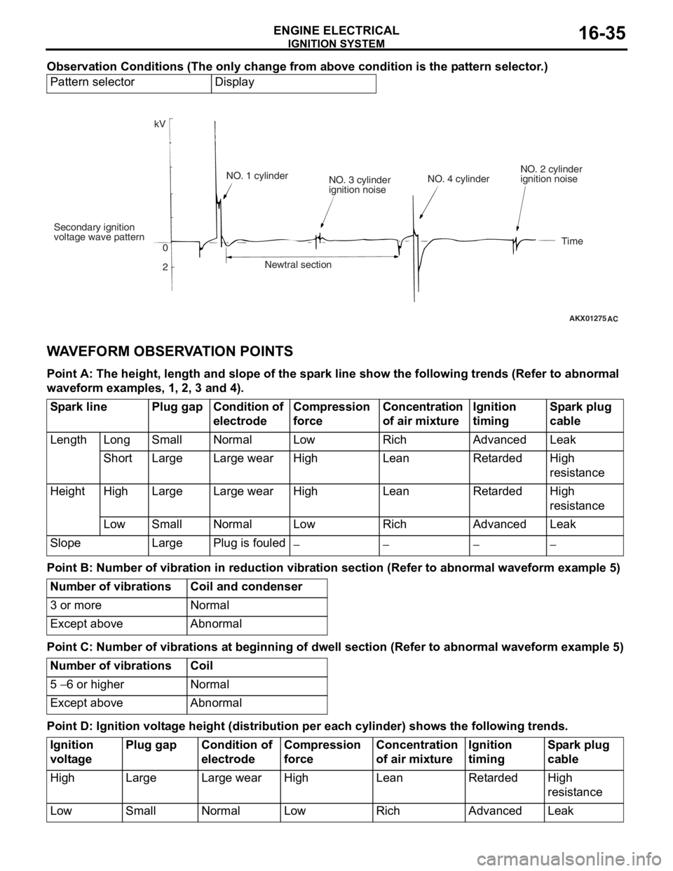
Observation Conditions (The only change from above condition is the pattern selector.)
Pattern selectorDisplay
AKX01275
kV
Secondary ignition
voltage wave pattern 0
2NO. 1 cylinder
NO. 3 cylinder
ignition noise
Newtral section NO. 4 cylinder
NO. 2 cylinder
ignition noise
Time
AC
WA VEFORM OBSER V A T ION POINTS
Point A: The he ight, len g th and s l ope of th e sp a r k line sho w the following trends (Re f er to abnorma l
wave
form exam ples, 1 , 2, 3 a nd 4).
Spark linePlug gapCondition of
electrodeCompression
force Concentration
of air mixtureIgnition
timingSpark plug
cable
LengthLongSmallNormalLowRichAdvancedLeak
ShortLargeLarge wearHigh LeanRetardedHigh
resistance
HeightHighLargeLarge wearHighLeanRetardedHigh
resistance
LowSmallNormalLow RichAdvancedLeak
SlopeLargePlug is fouled−−−−
Point B: Number of v i bra t ion in red uction vi bra t ion sec tion (Refer to a bnormal wavefo r m examp l e 5)
Number of vibrationsCoil and condenser
3 or moreNormal
Except aboveAbnormal
Point C: Number of v i bra t ions a t beginnin g of dwell se ction (Refer to a bnormal wave form exam ple 5)
Number of vibrationsCoil
5 − 6 or higherNormal
Except aboveAbnormal
Point D: Ignition volt a g e height (distribution per each cylinder) s hows the follo wing tren ds.
Ignition
voltagePlug gapCondition of
electrodeCompression
forceConcentration
of air mixtureIgnition
timingSpark plug
cable
HighLargeLarge wearHighLeanRetardedHigh
resistance
LowSmallNormalLowRichAdvancedLeak
Page 233 of 800

GENERAL INFORMATION
POWER STEERING37-3
GENERAL INFORMATION
M1372000100661
Power steering has been adopted in all vehicles to
make the steering system easier to handle.
FEATURES
•A 4-spoke steering wheel is used.
•MOMO leather-wrapped 3-spoke steering wheel
is used.
•A steering column has a shock absorbing mecha-
nism and a tilt steering mechanism.
•Integral-type rack and pinion gear with high rigid-
ity and excellent response is used.
•A vane type pump with a fluid flow rate control
system which change steering effort according to
the engine speed is used.
•The separate plastic resin oil reservoir is used to
reduce weight and to make the fluid level check
-
ing easier.
SPECIFICATIONS
ItemInviteIntense
Steering
wheelTy p e4-spoke typeMOMO leather-wrapped
3-spoke type
Outside diameter mm380365
Maximum number of turns3.193.08
Steering
columnColumn mechanismShock absorbing mechanism and Tilt steering mechanism
Power steering typeIntegral type
Oil pumpTy p eVane pump
Basic discharge amount cm3/rev.7.2 <1300, 1600>
8.1 <2000>
7.2 <1300, 1600>
8.1 <2000>
Relief pressure MPa8.88.8
Reservoir typeSeparate type (plastic)
Pressure switchEquipped
Steering
gearTy p eRack and pinion
Stroke ratio (Rack stroke/Steering
wheel maximum turning radius)45.7445.74
Rack stroke mm146141
Page 236 of 800

SERVICE SPECIFICATIONS
POWER STEERING37-6
SERVICE SPECIFICATIONS
M1372000300795
ItemStandard valueLimit
Steering wheel free
play mmWith engine running−30
With engine stopped10 or less−
Steering angleInner wheelInvite39°30' ± 1°30'−
Intense (LH drive vehicles)33°40' +1°00'/-2°00'−
Intense (RH drive vehicles)37°00' +1°00'/-2°00'−
Outer wheel
(reference)Invite32°30'−
Intense (LH drive vehicles)28°46'−
Intense (RH drive vehicles)30°00'−
Toe-inAt the centre of tyre tread mm1 ± 2−
Toe-angle (per wheel)0°03' ± 06'−
Tie rod end ball joint turning torque N⋅m0.5 − 2.5−
Tie rod swing resistance N [Tie rod swing torque N⋅m]8 − 27 [1.5 − 4.9]−
Stationary steering effort N [Fluctuation allowance N]29 or less [5.9 or less]−
Oil pump pressure
MPa (750
± 100 r/min.)
Oil pump relief pressure8.8 − 9.5−
Pressure under no-load conditions0.2 − 0.7−
Steering gear retention hydraulic pressure8.8 − 9.5−
Oil pressure switch operating pressure
MPaOFF → ON1.5 − 2.0−
ON → OFF0.7 − 2.0−
Steering gear total pinion torque N⋅m
[Change in torque N
⋅m]
Invite0.8 − 2.1 [0.6 or less]−
Intense0.7 − 2.1 [0.6 or less]−
Opening dimension of special tool boot band crimping tool (MB991561)
mm2.9−
Band crimped width mm2.4 − 2.8−
Page 243 of 800

ON-VEHICLE SERVICE
POWER STEERING37-13
STEERING WHEEL RETURN TO CENTRE
CHECK
M1372001800317
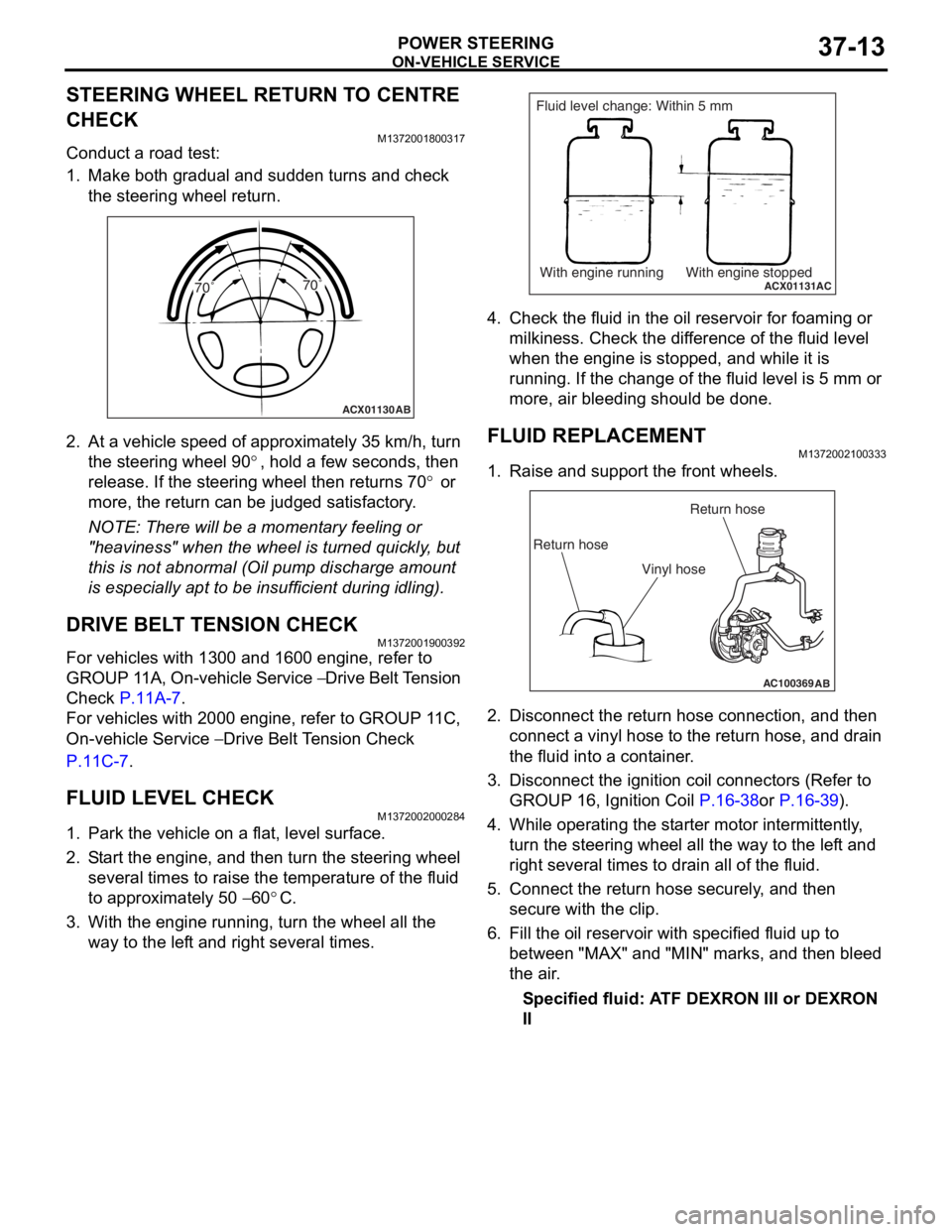
Conduct a road test:
1. Make both gradual and sudden turns and check the steering wheel return.
ACX01130 AB
70˚ 70˚
2.
At a vehicle sp eed of a pproxima t ely 35 km/h, turn
th e ste e ring wh eel 9 0
°, ho ld a few se cond s, the n
release. If th
e ste
e
ring
wh eel t hen ret u rns 7 0
° or
more, th
e return
can
be ju
dged satisfactory
.
NOTE: There will be a mome nt a r y fee lin g or
"he
a
viness" when t he wheel is turned quickly , but
th
is is n o t abno rmal (Oil pu mp discharge amou nt
is especially a p t to b e insufficie n t during id lin g).
DRIVE BELT TENSION CHECK
M13720019 0039 2
For vehicles with 13 00 and 1600 engin e , refer to
GROUP 1
1 A, On-vehicle Service
− Drive Belt T ension
Che
c
k
P.11A-7.
For veh i cles wit h 2000 e ngin e , refer to GROUP 1 1 C,
On-vehicle Se
rvice
− Drive Belt Te nsion Check
P.1 1 C - 7.
FLUID LEVEL CHECK
M13720020 0028 4
1.Park the vehicle on a f l at, leve l su rface .
2.S t art the engine, and t hen tu rn the ste e ring wheel
seve ral times to raise the temperat ure of th e flu i d
to approximately 50
− 60°C.
3.With the engine run n ing, turn the wheel all the
way to the lef t an d righ t several times.
ACX01131With engine running With engine stoppedAC
Fluid level change: Within 5 mm
4.Check t he flu i d in the oil r e servoir f o r foaming or
milkine s s. Check the d i f f e r ence of the fluid le vel
when the e ngine is stop ped, an d while it is
ru nning . If the chan ge of th e fluid le vel is 5 mm or
more, a i r bleedin g sh ould be don e.
FLUID REPLACEMENT
M13720021 0033 3
1.Raise a nd su pport t he fron t wheels.
AC100369AB
Return hoseReturn hose
Vinyl hose
2. Disco nnect the re turn hose connection , and then
conne ct a vinyl hose to the re turn h o se, and drain
th e flu i d into a cont ain e r .
3.Disco nnect the ignition coil con necto rs (Refe r to
GROUP 16, Ignition Coil
P.16-38or P.16-39).
4.Wh ile operat ing th e st arter moto r inter m itt ently ,
tu rn the steering whee l all the wa y to t he le f t a nd
right seve ral times to dra i n all of the fluid.
5.Conn ect the retu rn hose se curely , and then
secu re with t he clip.
6.Fill the oil reservo i r with specified fluid u p to
b e tween "MAX" and "MIN" marks, and then bleed
th e air .
Specified fluid: A TF DEXRON III or DEXRON
II
Page 244 of 800

ON-VEHICLE SERVICE
POWER STEERING37-14
POWER STEERING SYSTEM AIR
BLEEDING
M1372002200330
Perform air bleeding procedure as necessary after
replacing the steering gear or the steering fluid lines.
1. Raise and support the front wheels.
2. Disconnect the ignition coil connectors (Refer to GROUP 16, Ignition Coil
P.16-38 or P.16-39).
CAUTION
Perform air bleeding only while cranking the
engine. If air bleeding is performed while the
engine is running, air could enter the fluid. Dur
-
ing air bleeding, refill the steering fluid supply so
that the level never falls below the "MIN" mark on
the oil reservoir.
3. Turn the steering wheel all the way to the left and
right five or six times wh ile using the starter motor
to crank the engine intermittently several times
(for 15 to 20 seconds).
4. Connect the ignition coil connectors (Refer to GROUP 16, Ignition Coil
P.16-38 or P.16-39).
5. Start the engine (idling).
6. Turn the steering wheel to the left and right until there are no air bubbles in the oil reservoir.
7. Confirm that the fluid is not milky, and that the level is between "MAX" and "MIN" marks.
8. Confirm that there is very little change in the fluid
level when the steering wheel is turned left and
right.
CAUTION
If the fluid level rises suddenly after the engine is
stopped, the air has not been completely bled. If
air bleeding is not complete, there will be abnor
-
mal noises from the pump and the flow-control
valve, and this condition could cause reduce the
life of the power steering components.
ACX01131With engine running With engine stoppedAC
Fluid level change: Within 5 mm
9. Confirm that the change in the fluid level is no more than 5 mm when the engine is stopped and
when it is running.
10.If the change of the fluid level is 5 mm or more,
the air has not been completely bled from the
system. The air bleeding procedure must be
repeated.
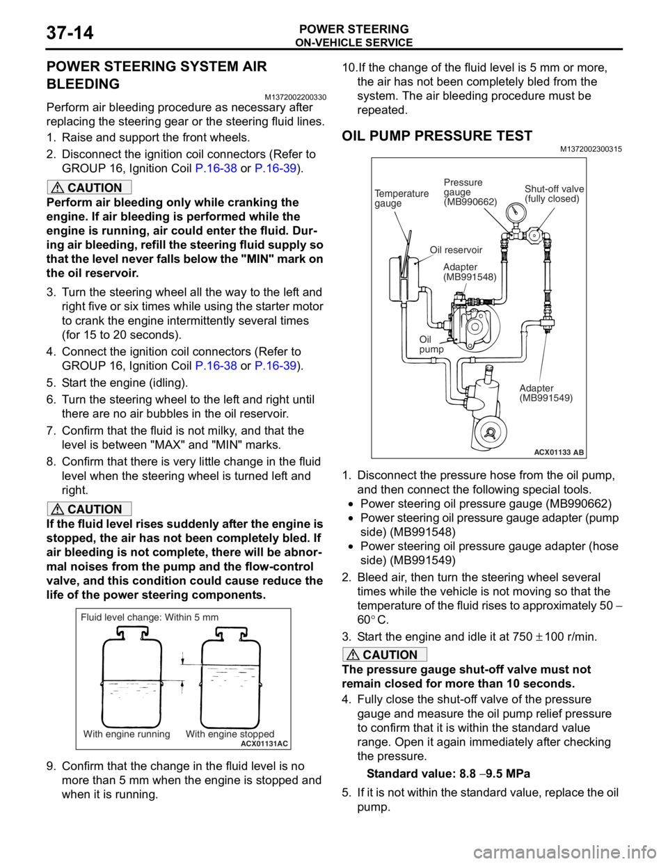
OIL PUMP PRESSURE TEST
M1372002300315
ACX01133
Temperature
gauge
Oil reservoir
Adapter
(MB991548)
Oil
pump Adapter
(MB991549)
AB
Shut-off valve
(fully closed)
Pressure
gauge
(MB990662)
1. Disconnect the pressure hose from the oil pump,
and then connect the following special tools.
•Power steering oil pressure gauge (MB990662)
•Power steering oil pressure gauge adapter (pump
side) (MB991548)
•Power steering oil pressure gauge adapter (hose
side) (MB991549)
2. Bleed air, then turn the steering wheel several times while the vehicle is not moving so that the
temperature of the fluid rises to approximately 50
−
60
°C.
3. Start the engine and idle it at 750 ± 100 r/min.
CAUTION
The pressure gauge shut-off valve must not
remain closed for more than 10 seconds.
4. Fully close the shut-off valve of the pressure gauge and measure the oil pump relief pressure
to confirm that it is within the standard value
range. Open it again immediately after checking
the pressure.
Standard value: 8.8 − 9.5 MPa
5. If it is not within the standard value, replace the oil pump.