Reverse sensor MITSUBISHI LANCER 2006 Workshop Manual
[x] Cancel search | Manufacturer: MITSUBISHI, Model Year: 2006, Model line: LANCER, Model: MITSUBISHI LANCER 2006Pages: 800, PDF Size: 45.03 MB
Page 95 of 800

IGNITION SYSTEM
ENGINE ELECTRICAL16-33
SPARK PLUG CHECK AND CLEANING
<4G6>
M1163004300353
CAUTION
When pulling off the spark plug cable from the
plug always hold the cable cap, not the cable.
1. Remove the spark plug cables.
2. Remove the spark plugs.
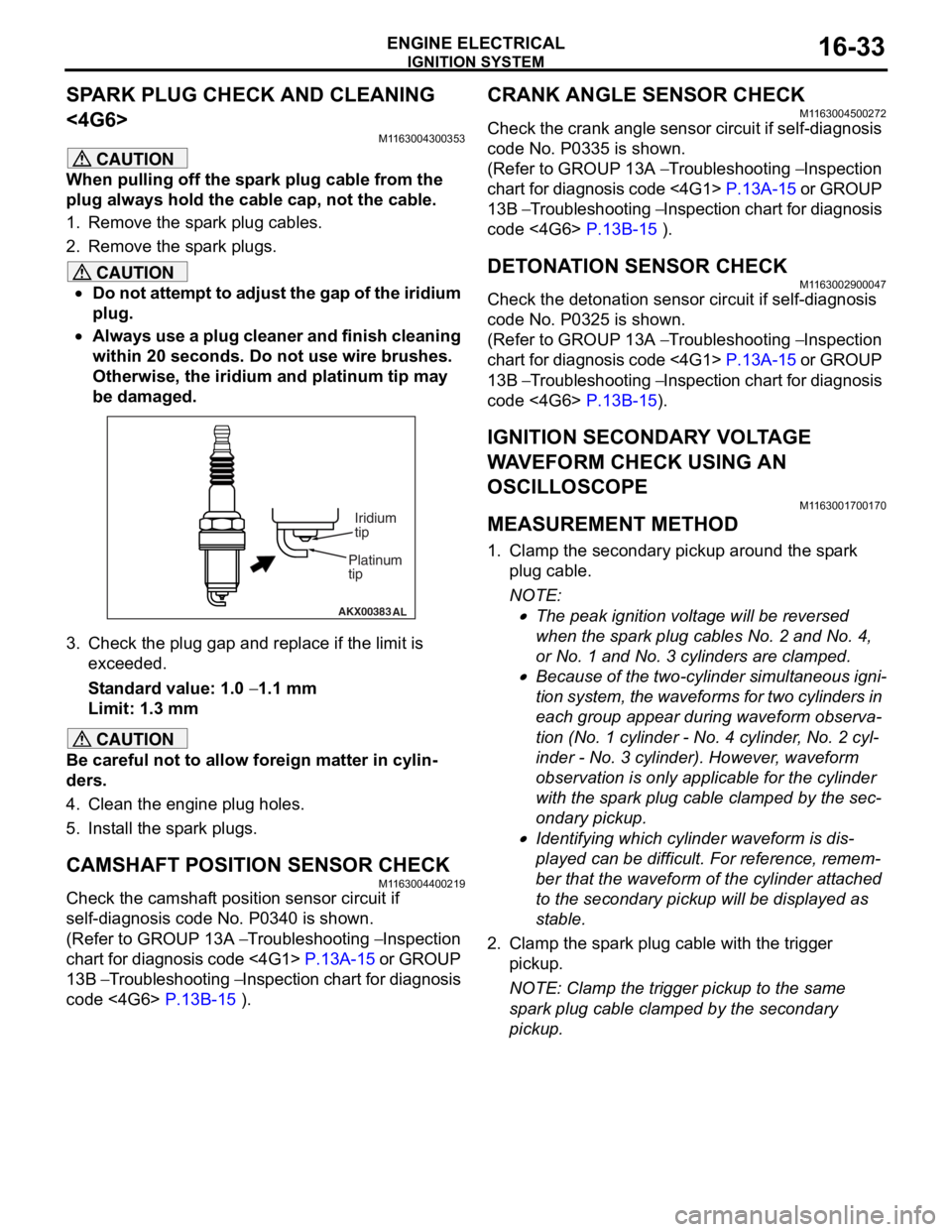
CAUTION
•Do not attempt to adjust the gap of the iridium
plug.
•
AKX00383 AL
Platinum
tipIridium
tip
Always use a plug cleaner and finish cleaning
within 20 seconds. Do not use wire brushes.
Otherwise, the iridium and platinum tip may
be damaged.
3. Check the plug gap and re
place if the limit is
exceeded.
Standard value: 1.0 − 1.1 mm
Limit: 1.3 mm
CAUTION
Be careful not to allow foreign matter in cylin-
ders.
4. Clean the engine plug holes.
5. Install the spark plugs.
CAMSHAFT POSITION SENSOR CHECK
M1163004400219
Check the camshaft position sensor circuit if
self-diagnosis code No. P0340 is shown.
(Refer to GROUP 13A − Troubleshooting − Inspection
chart for diagnosis code <4G1>
P.13A-15 or GROUP
13B − Troubleshooting − Inspection chart for diagnosis
code <4G6>
P.13B-15 ).
CRANK ANGLE SENSOR CHECK
M1163004500272
Check the crank angle sensor circuit if self-diagnosis
code No. P0335 is shown.
(Refer to GROUP 13A − Troubleshooting − Inspection
chart for diagnosis code <4G1>
P.13A-15 or GROUP
13B − Troubleshooting − Inspection chart for diagnosis
code <4G6>
P.13B-15 ).
DETONATION SENSOR CHECKM1163002900047
Check the detonation sensor circuit if self-diagnosis
code No. P0325 is shown.
(Refer to GROUP 13A − Troubleshooting − Inspection
chart for diagnosis code <4G1>
P.13A-15 or GROUP
13B − Troubleshooting − Inspection chart for diagnosis
code <4G6>
P.13B-15).
IGNITION SECONDARY VOLTAGE
WAVEFORM CHECK USING AN
OSCILLOSCOPE
M1163001700170
MEASUREMENT METHOD
1. Clamp the secondary pickup around the spark
plug cable.
NOTE: .
•The peak ignition voltage will be reversed
when the spark plug cables No. 2 and No. 4,
or No. 1 and No. 3 cylinders are clamped.
•Because of the two-cylinder simultaneous igni-
tion system, the waveforms for two cylinders in
each group appear during waveform observa
-
tion (No. 1 cylinder - No. 4 cylinder, No. 2 cyl-
inder - No. 3 cylinder). However, waveform
observation is only applicable for the cylinder
with the spark plug cable clamped by the sec
-
ondary pickup.
•Identifying which cylinder waveform is dis-
played can be difficult. For reference, remem-
ber that the waveform of the cylinder attached
to the secondary pickup will be displayed as
stable.
2. Clamp the spark plug cable with the trigger pickup.
NOTE: Clamp the trigger pickup to the same
spark plug cable clamped by the secondary
pickup.
Page 560 of 800

INVECS-II 4A/T
CIRCUIT DIAGRAMS90-96
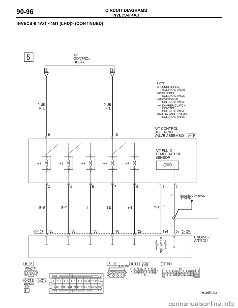
INVECS-II 4A/T <4G1 (LHD)> (CONTINUED)
A/T
CONTROL
RELAY
A/T CONTROL
SOLENOID
VALVE ASSEMBLY
ENGINE CONTROL
SYSTEM
ENGINE-
A/T-ECU
NOTE
:
:
:
:
: UNDERDRIVE
SOLENOID VALVE
SECOND
SOLENOID VALVE
DAMPER CLUTCH
CONTROL
SOLENOID VALVE OVERDRIVE
SOLENOID VALVE
LOW AND REVERSE
SOLENOID VALVE
A/T FLUID
TEMPERATURE
SENSOR
FRONT
SIDE
Page 566 of 800

INVECS-II 4A/T
CIRCUIT DIAGRAMS90-102
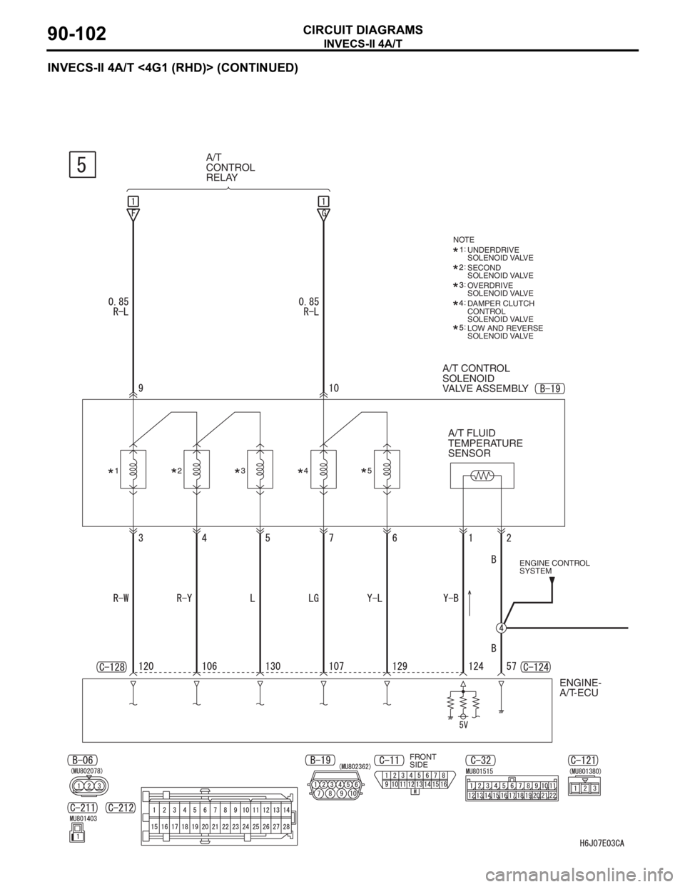
INVECS-II 4A/T <4G1 (RHD)> (CONTINUED)
A/T CONTROL
SOLENOID
VALVE ASSEMBLY
NOTE
:
:
:
:
: UNDERDRIVE
SOLENOID VALVE
SECOND
SOLENOID VALVE
DAMPER CLUTCH
CONTROL
SOLENOID VALVE OVERDRIVE
SOLENOID VALVE
LOW AND REVERSE
SOLENOID VALVE
A/T
CONTROL
RELAY
ENGINE CONTROL
SYSTEM
ENGINE-
A/T-ECU
FRONT
SIDE
A/T FLUID
TEMPERATURE
SENSOR
Page 572 of 800

INVECS-II 4A/T
CIRCUIT DIAGRAMS90-108
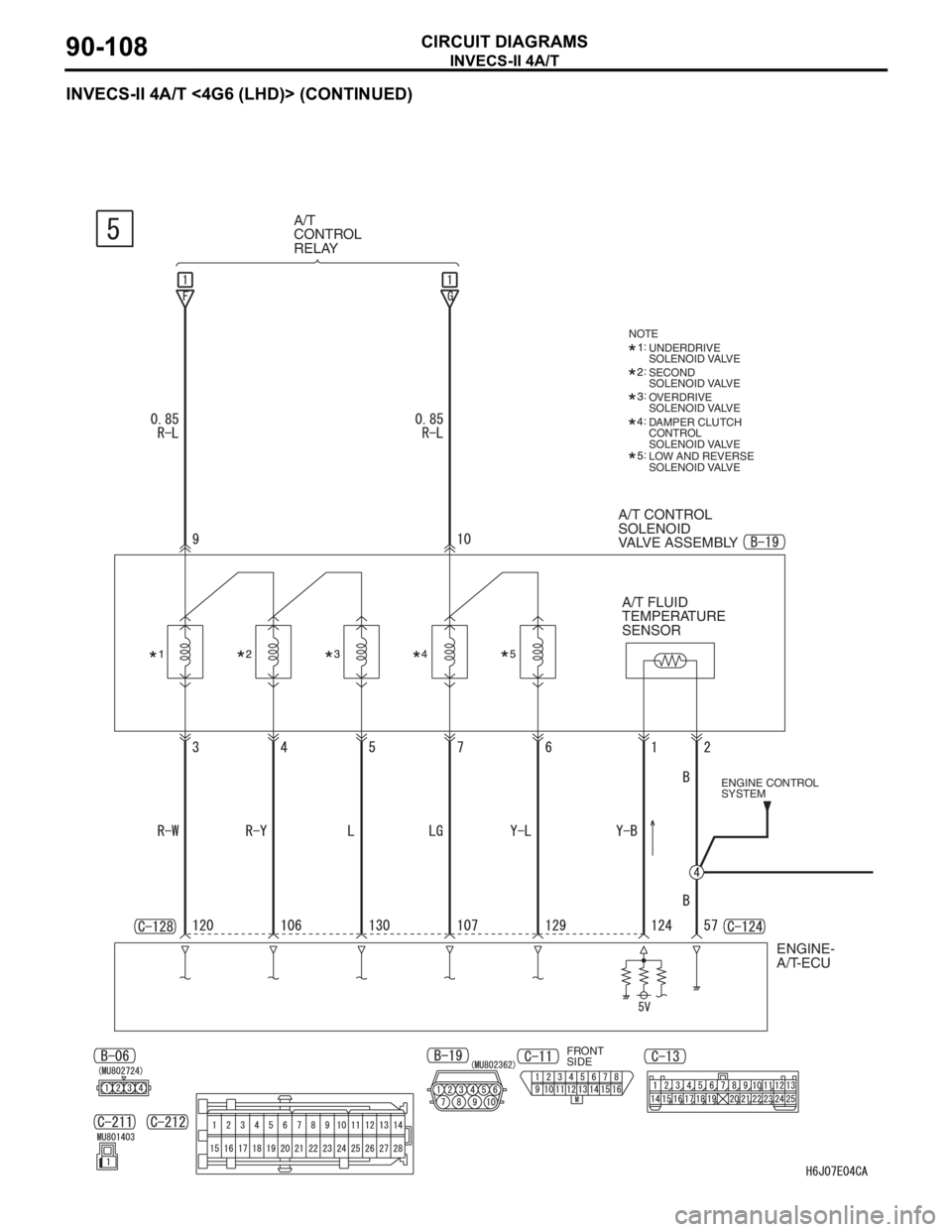
INVECS-II 4A/T <4G6 (LHD)> (CONTINUED)
A/T
CONTROL
RELAY
A/T CONTROL
SOLENOID
VALVE ASSEMBLY
ENGINE CONTROL
SYSTEM
ENGINE-
A/T-ECU
NOTE
:
:
:
:
: UNDERDRIVE
SOLENOID VALVE
SECOND
SOLENOID VALVE
DAMPER CLUTCH
CONTROL
SOLENOID VALVE OVERDRIVE
SOLENOID VALVE
LOW AND REVERSE
SOLENOID VALVE
A/T FLUID
TEMPERATURE
SENSOR
FRONT
SIDE