Transmission fluid MITSUBISHI LANCER 2006 Workshop Manual
[x] Cancel search | Manufacturer: MITSUBISHI, Model Year: 2006, Model line: LANCER, Model: MITSUBISHI LANCER 2006Pages: 800, PDF Size: 45.03 MB
Page 137 of 800
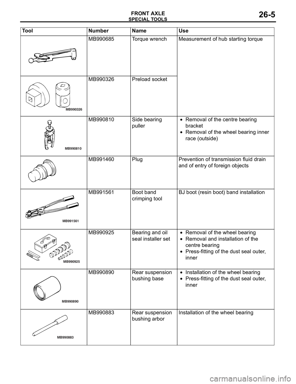
SPECIA L T OOLS
FRONT AXLE26-5
MB990685To rqu e wrenchMeas urement o f hub st arting torque
MB990326
MB990326 Prel oad socket
MB990810
MB990810Side be aring
puller•Removal of the centre b earing
bra
c ke t
•Removal of the whee l bea ring inner
r
a ce (o ut side )
MB991460PlugPreven tion of transmission fluid drain
and o
f entry of fore ign o b ject s
MB991561
MB991561Boot ban d
crimpin
g toolBJ boot (resin bo ot) ban d inst a lla tion
MB990925
MB990925Bearing and o il
seal
inst a lle r set•Removal of the whee l bea ring
•Removal and inst a lla tion o f the
centre
bearing
•Press-f i ttin g of th e dust se al ou ter ,
inner
MB990890
MB990890Rear suspension
bush
i ng b a se•In st allatio n of th e wheel bearing
•Press-f i ttin g of th e dust se al ou ter ,
inner
MB990883
MB990883Rear suspension
bush
i ng a r borInstallation of t he wheel bearing
Tool Nu mber Na me Use
Page 146 of 800
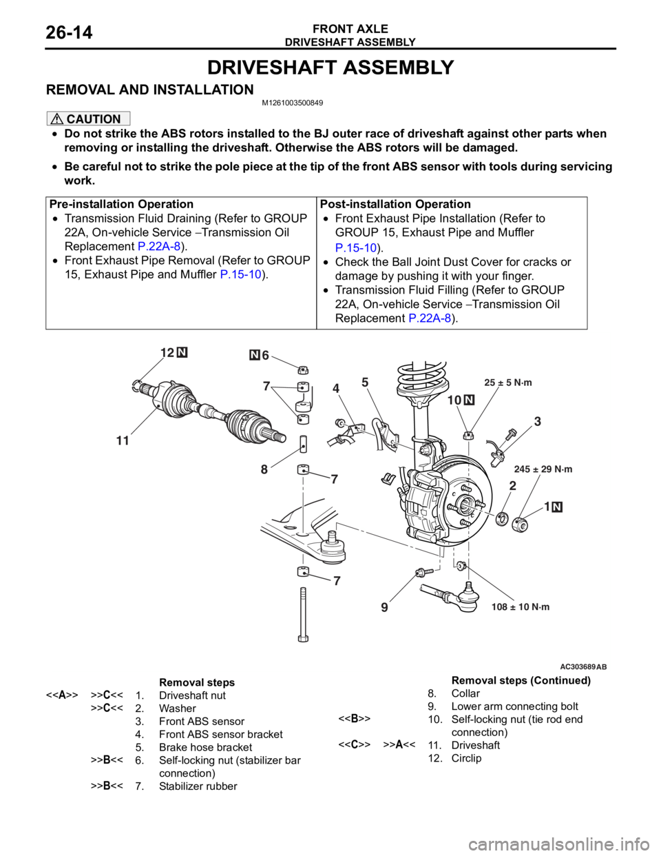
DRIVESHAFT ASSEMBLY
FRONT AXLE26-14
DRIVESHAFT ASSEMBLY
REMOVAL AND INSTALLATIONM1261003500849
CAUTION
•Do not strike the ABS rotors installed to the BJ outer race of driveshaft against other parts when
removing or installing the driveshaft. Otherwise the ABS rotors will be damaged.
•
Pre-installation Operation
•Transmission Fluid Draining (Refer to GROUP
22A, On-vehicle Service
− Transmission Oil
Replacement
P.22A-8).
•Front Exhaust Pipe Removal (Refer to GROUP
15, Exhaust Pipe and Muffler
P.15-10).
Post-installation Operation
•Front Exhaust Pipe Installation (Refer to
GROUP 15, Exhaust Pipe and Muffler
P.15-10).
•Check the Ball Joint Dust Cover for cracks or
damage by pushing it with your finger.
•Transmission Fluid Filling (Refer to GROUP
22A, On-vehicle Service
− Transmission Oil
Replacement
P.22A-8).
AC303689AB
9
N
N
NN
10
7
4
3
2 1
25 ± 5 N·m
245 ± 29 N·m
108 ± 10 N·m
8
5
6
11 12
77
Removal steps
<>>>C<<1.Driveshaft nut
>>C<<2.Washer
3.Front ABS sensor
4.Front ABS sensor bracket
5.Brake hose bracket
>>B<<6.Self-locking nut (stabilizer bar
connection)
>>B<<7.Stabilizer rubber
8.Collar
9.Lower arm connecting bolt
<>10.Self-locking nut (tie rod end
connection)
<
12.Circlip
Be careful not to strike the pole piece at the tip of the front ABS sensor with tools during servicing
work.
Removal steps (Continued)
Page 420 of 800
ENGINE AND TRANSMISSION
CONFIGURATION DIAGRAMS80-10
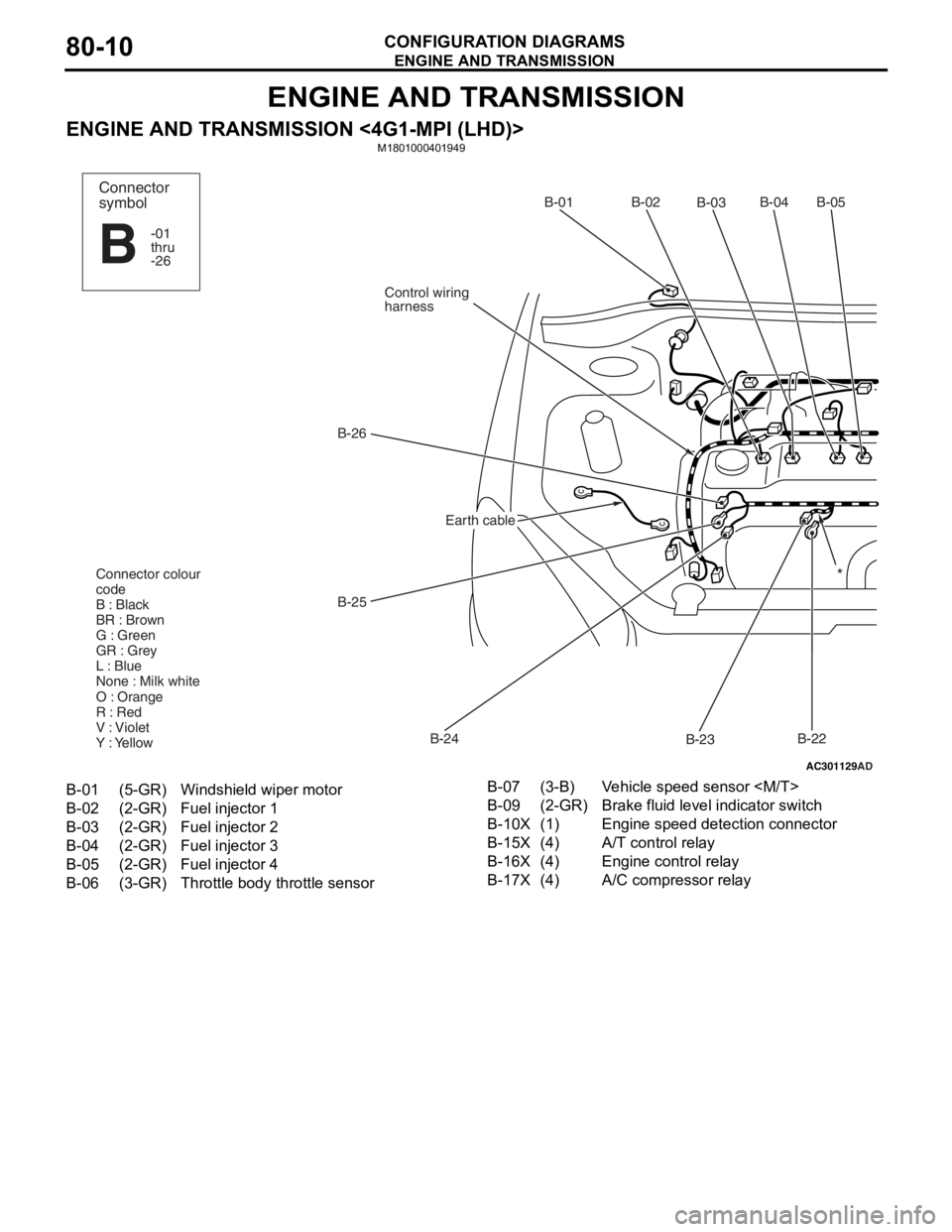
ENGINE AND TRANSMISSION
ENGINE AND TRANSMISSION <4G1-MPI (LHD)>M1801000401949
AC301129
AD
B-02
B-03B-04B-05
B-22
B-23
B-24
B-25
B-26
Control wiring
harnessB-01
Connector colour
code
B : Black
BR : Brown
G : Green
GR : Grey
L : Blue
None : Milk white
O : Orange
R : Red
V : Violet
Y : Yellow*
Connector
symbol
-01
thru
-26
B
Earth cable
B-01(5-GR)Windshield wiper motor
B-02(2-GR)Fuel injector 1
B-03(2-GR)Fuel injector 2
B-04(2-GR)Fuel injector 3
B-05(2-GR)Fuel injector 4
B-06(3-GR)Throttle body throttle sensor
B-07(3-B)Vehicle speed sensor
B-09(2-GR)Brake fluid level indicator switch
B-10X(1)Engine speed detection connector
B-15X(4)A/T control relay
B-16X(4)Engine control relay
B-17X(4)A/C compressor relay
Page 424 of 800
ENGINE AND TRANSMISSION
CONFIGURATION DIAGRAMS80-14
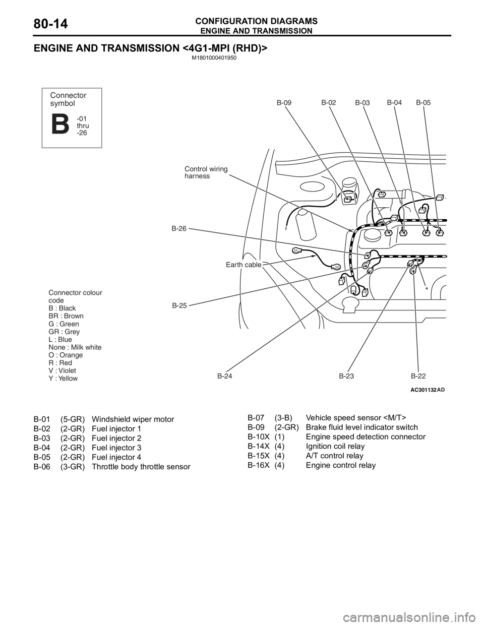
ENGINE AND TRANSMISSION <4G1-MPI (RHD)>
M1801000401950
AC301132AD
B-02
B-03B-04 B-05
B-22
B-23
B-24
B-25
B-26
Control wiring
harnessB-09
Connector colour
code
B : Black
BR : Brown
G : Green
GR : Grey
L : Blue
None : Milk white
O : Orange
R : Red
V : Violet
Y : Yellow*
Connector
symbol
-01
thru
-26
B
Earth cable
B-01(5-GR)Windshield wiper motor
B-02(2-GR)Fuel injector 1
B-03(2-GR)Fuel injector 2
B-04(2-GR)Fuel injector 3
B-05(2-GR)Fuel injector 4
B-06(3-GR)Throttle body throttle sensor
B-07(3-B)Vehicle speed sensor
B-09(2-GR)Brake fluid level indicator switch
B-10X(1)Engine speed detection connector
B-14X(4)Ignition coil relay
B-15X(4)A/T control relay
B-16X(4)Engine control relay
Page 428 of 800
ENGINE AND TRANSMISSION
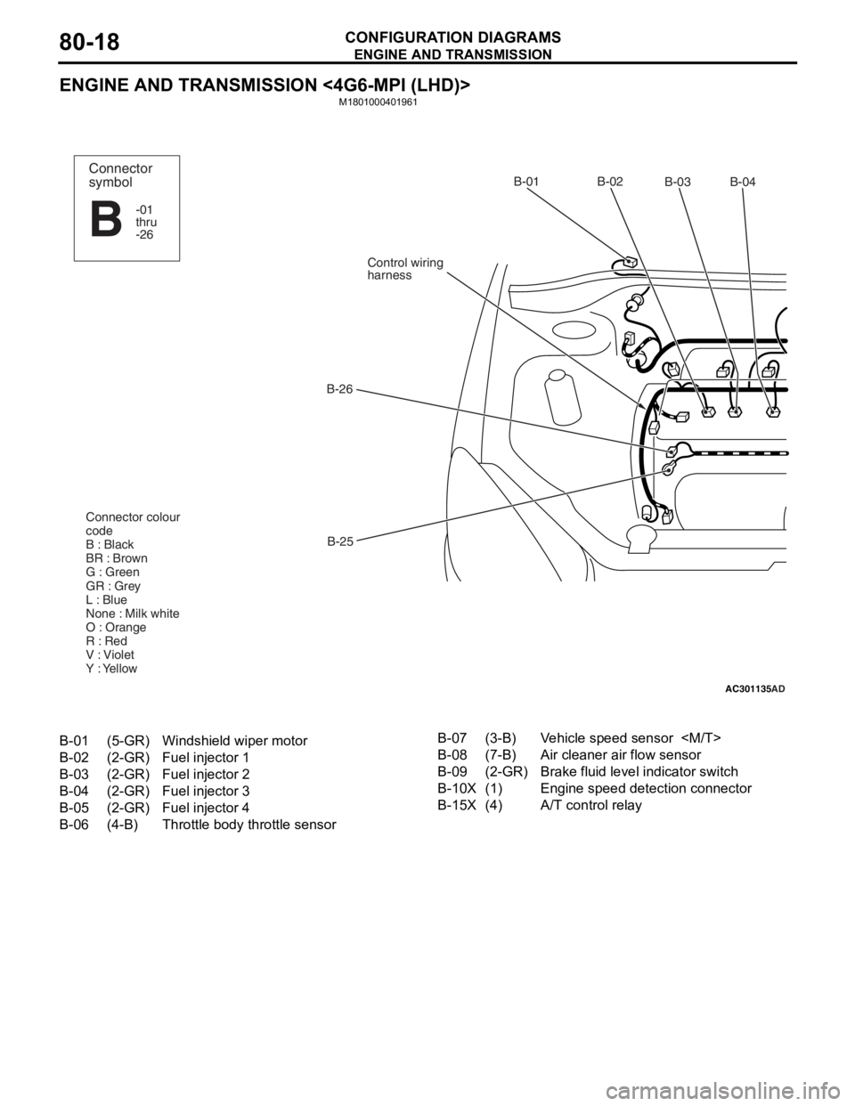
CONFIGURATION DIAGRAMS80-18
ENGINE AND TRANSMISSION <4G6-MPI (LHD)>
M1801000401961
AC301135AD
B-02
B-03B-04
B-25
B-26
Control wiring
harnessB-01
Connector colour
code
B : Black
BR : Brown
G : Green
GR : Grey
L : Blue
None : Milk white
O : Orange
R : Red
V : Violet
Y : YellowConnector
symbol
-01
thru
-26
B
B-01(5-GR)Windshield wiper motor
B-02(2-GR)Fuel injector 1
B-03(2-GR)Fuel injector 2
B-04(2-GR)Fuel injector 3
B-05(2-GR)Fuel injector 4
B-06(4-B)Throttle body throttle sensor
B-07(3-B)Vehicle speed sensor
B-08(7-B)Air cleaner air flow sensor
B-09(2-GR)Brake fluid level indicator switch
B-10X(1)Engine speed detection connector
B-15X(4)A/T control relay
Page 432 of 800
ENGINE AND TRANSMISSION
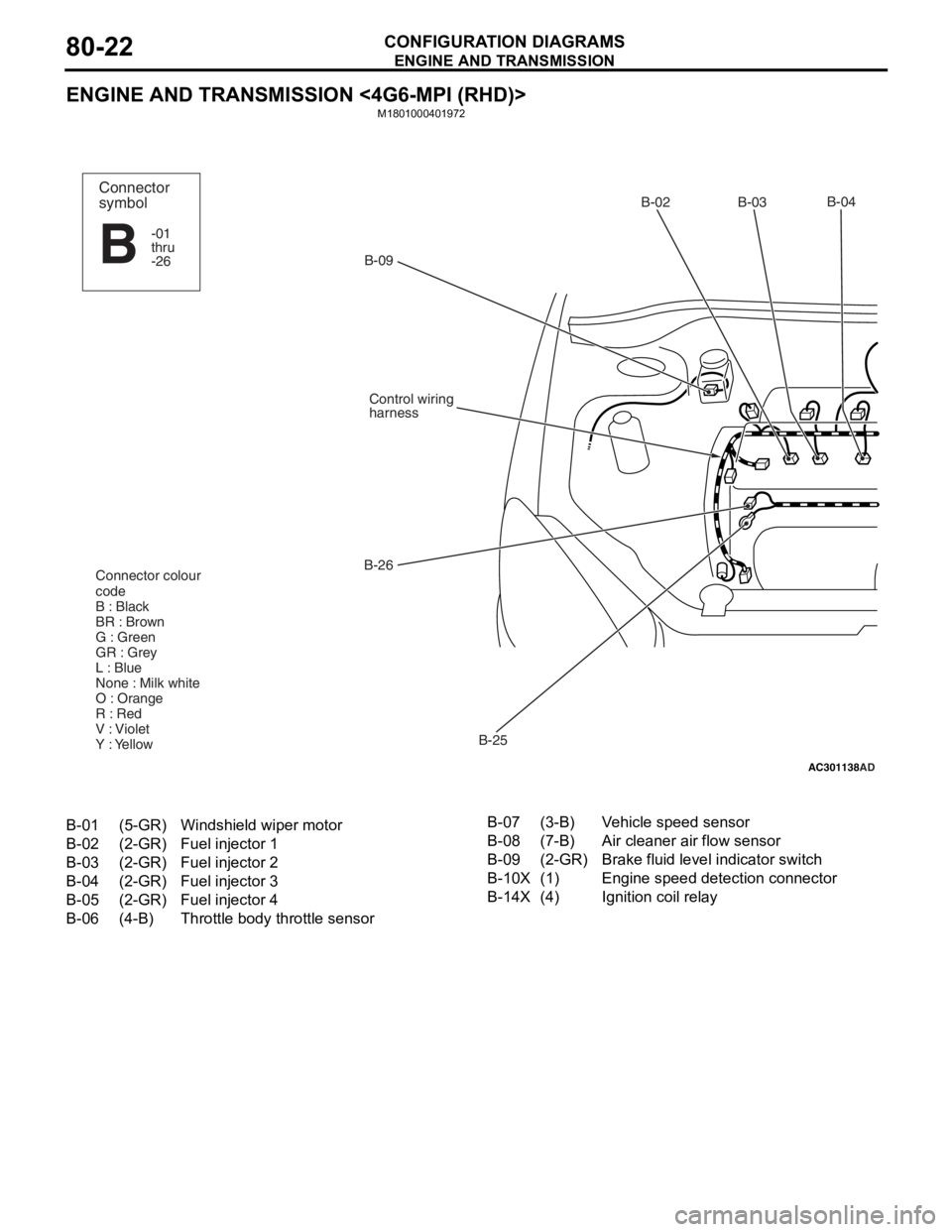
CONFIGURATION DIAGRAMS80-22
ENGINE AND TRANSMISSION <4G6-MPI (RHD)>
M1801000401972
AC301138
AD
B-02 B-03B-04
B-25
B-26
Control wiring
harness
B-09
Connector colour
code
B : Black
BR : Brown
G : Green
GR : Grey
L : Blue
None : Milk white
O : Orange
R : Red
V : Violet
Y : Yellow
Connector
symbol
-01
thru
-26
B
B-01(5-GR)Windshield wiper motor
B-02(2-GR)Fuel injector 1
B-03(2-GR)Fuel injector 2
B-04(2-GR)Fuel injector 3
B-05(2-GR)Fuel injector 4
B-06(4-B)Throttle body throttle sensor
B-07(3-B)Vehicle speed sensor
B-08(7-B)Air cleaner air flow sensor
B-09(2-GR)Brake fluid level indicator switch
B-10X(1)Engine speed detection connector
B-14X(4)Ignition coil relay