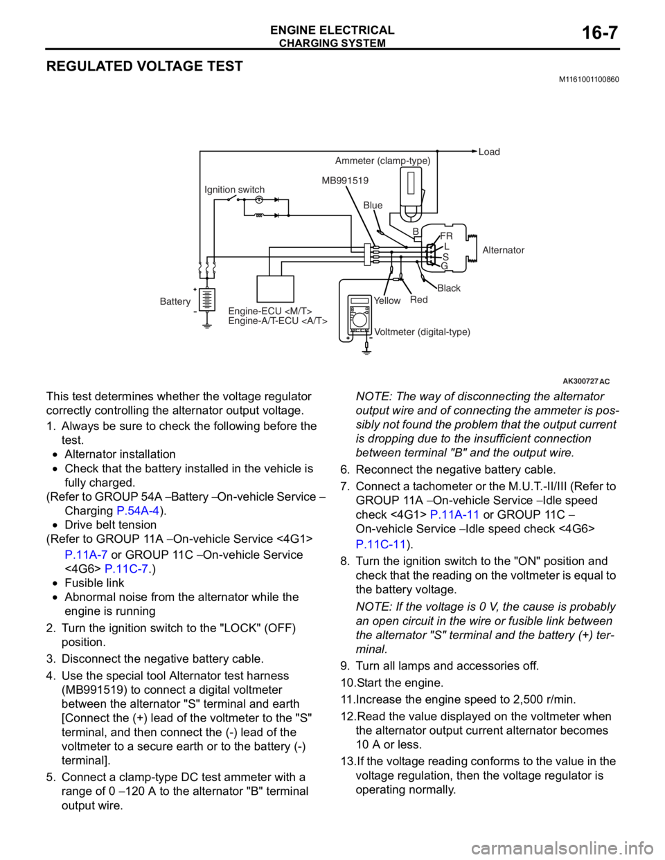
alternator MITSUBISHI LANCER 2006 Workshop Manual
[x] Cancel search | Manufacturer: MITSUBISHI, Model Year: 2006, Model line: LANCER, Model: MITSUBISHI LANCER 2006Pages: 800, PDF Size: 45.03 MB
Page 16 of 800

GENERAL INFORMATION
ENGINE COOLING14-2
GENERAL INFORMATION
M1141000100371
The cooling system is designed to keep every part of
the engine at appropriate temperature in whatever
condition the engine may be operated. The cooling
method is of the water-cooled, pressure forced circu
-
lation type in which the water pump pressurizes cool-
ant and circulates it throughout the engine. If the
coolant temperature exceeds the prescribed temper
-
ature, the thermostat opens to circulate the coolant
through the radiator as well so that the heat
absorbed by the coolant may be radiated into the air.
The water pump is of the centrifugal type and is
driven by the alternator drive belt from the crank
-
shaft. The radiator is the corrugated fin, down flow
type.
ItemSpecification
RadiatorPerformance kJ/h4G13Standard vehicles137,720
Vehicles with capacity up radiator
(option)161,288
4G18Standard vehicles161,288
Vehicles with capacity up radiator
(option)181,800
4G63181,800
A/T oil coolerPerformance kJ/h5,651
SERVICE SPECIFICATIONS
M1141000300687
ItemStandard valueLimit
Fan controller VA/C OFF1 or less-
A/C ONRepeat
8.2 ± 0.7
System voltage ± 2.6
-
High-pressure valve opening pressure of radiator cap kPa93 − 123Minimum 83
Range of coolant antifreeze concentration of radiator %30 − 60-
ThermostatValve opening temperature of
thermostat
°C
4G188 ± 1.5-
4G682 ± 1.5-
Full-opening temperature of
thermostat
°C
4G1100-
4G695-
Valve lift mm8.5 or more-
Page 41 of 800
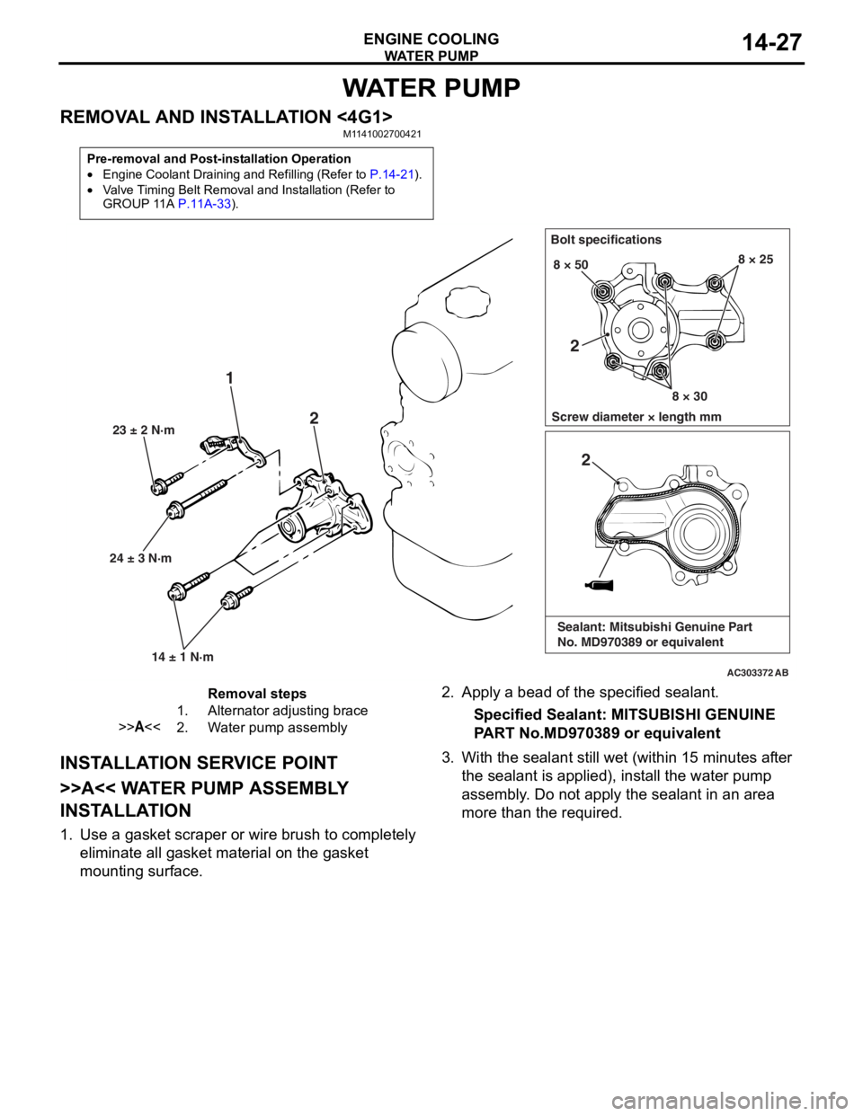
WATE R P U M P
ENGINE COOLING14-27
WAT E R P U M P
REMOVAL AND INSTALLATION <4G1>M1141002700421
Pre-removal and Post-installation Operation
•Engine Coolant Draining and Refilling (Refer to P.14-21).
•Valve Timing Belt Removal and Installation (Refer to
GROUP 11A P.11A-33).
AC303372
24 ± 3 N·m23 ± 2 N·m
14 ± 1 N·m
1 2
Bolt specifications
Screw diameter × length mm 8 × 50
8 × 308 × 25
AB
2
2
Sealant: Mitsubishi Genuine Part
No. MD970389 or equivalent
Removal steps
1.Alternator adjusting brace
>>A<<2.Water pump assembly
INST ALLA T ION SER VICE POINT
>>A<< WA TER PUMP ASSEMBL Y
INST
ALLA TION
1.Use a gaske t scraper o r wire brush to complet e ly
eliminate all gasket material o n the g a sket
mounting surface.
2. App l y a bead of the specified sealan t.
Specified Sealant: MITSUBISHI GENUINE
P
ART No.MD970 389 or eq uivalen t
3.With the sea l ant still wet (within 1 5 minutes af ter
th e se alant is applied), inst all the wa ter pump
a sse mbly . Do not a pply the sealant in an are a
more th an the required.
Page 42 of 800
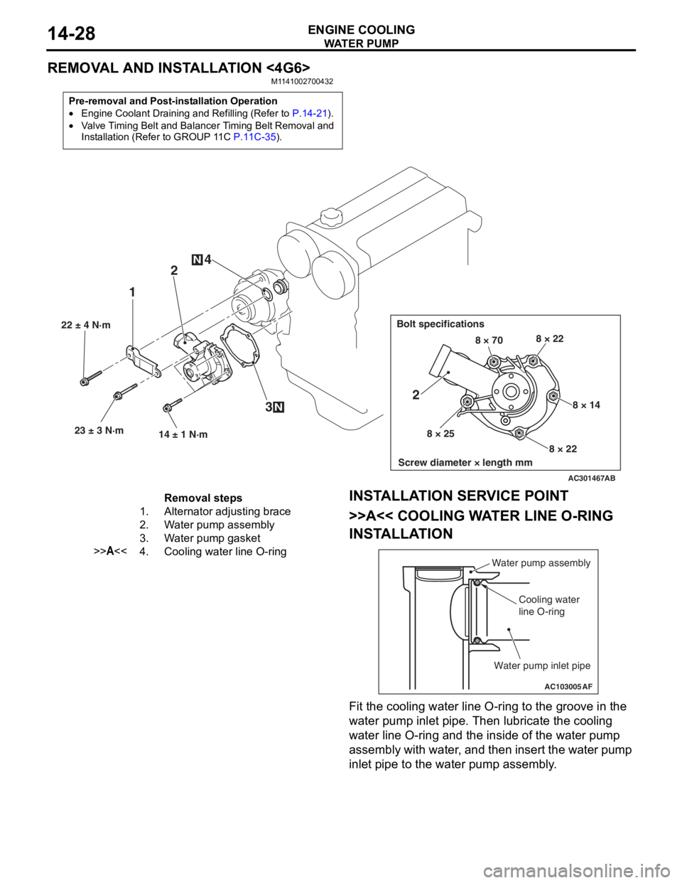
WATE R P U M P
ENGINE COOLING14-28
REMOVAL AND INSTALLATION <4G6>
M1141002700432
Pre-removal and Post-installation Operation
•Engine Coolant Draining and Refilling (Refer to P.14-21).
•Valve Timing Belt and Balancer Timing Belt Removal and
Installation (Refer to GROUP 11C
P.11C-35).
AC301467
22 ± 4 N·m23 ± 3 N·m 14 ± 1 N·m
12
3
4
N
N
Bolt specifications
Screw diameter × length mm
8 × 70 8 × 22
8 × 14
8 × 22
8 × 25
2
AB
Removal steps
1.Alternator adjusting brace
2.Water pump assembly
3.Water pump gasket
>>A<<4.Cooling water line O-ring
INST
ALLA T ION SER VICE POINT
>>A<< COOLING WA TER LINE O-RING
INST
ALLA TION
AC103005
Water pump assembly
Cooling water
line O-ring
Water pump inlet pipe
AF
Fit the coo ling water line O-ring to the groove in the
wa
ter pump in let p i pe. T hen lubricate th e co olin g
wa
ter line O-ring and the inside of the wat e r pump
assembly with wa
ter , and then insert the wa ter pu mp
inle
t pip e to the water pu mp asse mbly .
Page 63 of 800
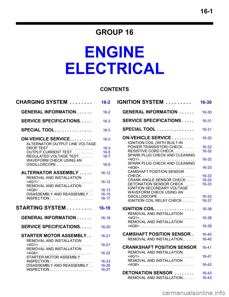
16-1
GROUP 16
ENGINE
ELECTRICAL
CONTENTS
CHARGING SYSTEM . . . . . . . .16-2
GENERAL INFORMATION . . . . . .16-2
SERVICE SPECIFICATIONS. . . . .16-3
SPECIAL TOOL . . . . . . . . . . . . . . .16-3
ON-VEHICLE SERVICE. . . . . . . . .16-3
ALTERNATOR OUTPUT LINE VOLTAGE
DROP TEST . . . . . . . . . . . . . . . . . . . . . 16-3
OUTPUT CURRENT TEST . . . . . . . . . . 16-5
REGULATED VOLTAGE TEST . . . . . . . 16-7
WAVEFORM CHECK USING AN
OSCILLOSCOPE . . . . . . . . . . . . . . . . . . 16-9
ALTERNATOR ASSEMB LY . . . . .16-12
REMOVAL AND INSTALLATION
<4G1> . . . . . . . . . . . . . . . . . . . . . . . . . . 16-12
REMOVAL AND INSTALLATION
<4G6> . . . . . . . . . . . . . . . . . . . . . . . . . . 16-13
DISASSEMBLY AND REASSEMBLY . . 16-15
INSPECTION . . . . . . . . . . . . . . . . . . . . . 16-17
STARTING SYSTEM . . . . . . . . .16-19
GENERAL INFORMATION . . . . . .16-19
SERVICE SPECIFICATIONS. . . . .16-20
STARTER MOTOR ASSEMBLY . .16-21
REMOVAL AND INSTALLATION
<4G1> . . . . . . . . . . . . . . . . . . . . . . . . . . 16-21
REMOVAL AND INSTALLATION
<4G6> . . . . . . . . . . . . . . . . . . . . . . . . . . 16-22
STARTER MOTOR ASSEMBLY
INSPECTION . . . . . . . . . . . . . . . . . . . . . 16-23
DISASSEMBLY AND REASSEMBLY . . 16-26
INSPECTION . . . . . . . . . . . . . . . . . . . . . 16-27
IGNITION SYSTEM . . . . . . . . . 16-30
GENERAL INFORMATION . . . . . .16-30
SERVICE SPECIFICATIONS . . . . .16-31
SPECIAL TOOL . . . . . . . . . . . . . . .16-31
ON-VEHICLE SERVICE . . . . . . . . .16-32
IGNITION COIL (WITH BUILT-IN
POWER TRANSISTOR) CHECK . . . . . . 16-32
RESISTIVE CORD CHECK . . . . . . . . . . 16-32
SPARK PLUG CHECK AND CLEANING
<4G1>. . . . . . . . . . . . . . . . . . . . . . . . . . . 16-32
SPARK PLUG CHECK AND CLEANING
<4G6>. . . . . . . . . . . . . . . . . . . . . . . . . . . 16-33
CAMSHAFT POSITION SENSOR
CHECK . . . . . . . . . . . . . . . . . . . . . . . . . . 16-33
CRANK ANGLE SENSOR CHECK . . . . 16-33
DETONATION SENSOR CHECK . . . . . 16-33
IGNITION SECONDARY VOLTAGE
WAVEFORM CHECK USING AN
OSCILLOSCOPE . . . . . . . . . . . . . . . . . . 16-33
IGNITION COIL RELAY CHECK . . . . . . 16-37
IGNITION COIL . . . . . . . . . . . . . . . .16-38
REMOVAL AND INSTALLATION
<4G1>. . . . . . . . . . . . . . . . . . . . . . . . . . . 16-38
REMOVAL AND INSTALLATION
<4G6>. . . . . . . . . . . . . . . . . . . . . . . . . . . 16-39
CAMSHAFT POSITION SENSOR .16-40
REMOVAL AND INSTALLATION . . . . . . 16-40
CRANKSHAFT POSITION SENSOR16-41
REMOVAL AND INSTALLATION
<4G1>. . . . . . . . . . . . . . . . . . . . . . . . . . . 16-41
REMOVAL AND INSTALLATION
<4G6>. . . . . . . . . . . . . . . . . . . . . . . . . . . 16-42
DETONATION SENSOR . . . . . . . .16-43
REMOVAL AND INSTALLATION . . . . . . 16-43
Page 64 of 800
CHARGING SYSTEM
ENGINE ELECTRICAL16-2
CHARGING SYSTEM
GENERAL INFORMATIONM1161000100522
The charging system uses the alternator output to
keep the battery charged at a constant level under
various electrical loads.
OPERATION
AKX00183
VoltageTime
Approximately
14.4 V
AC
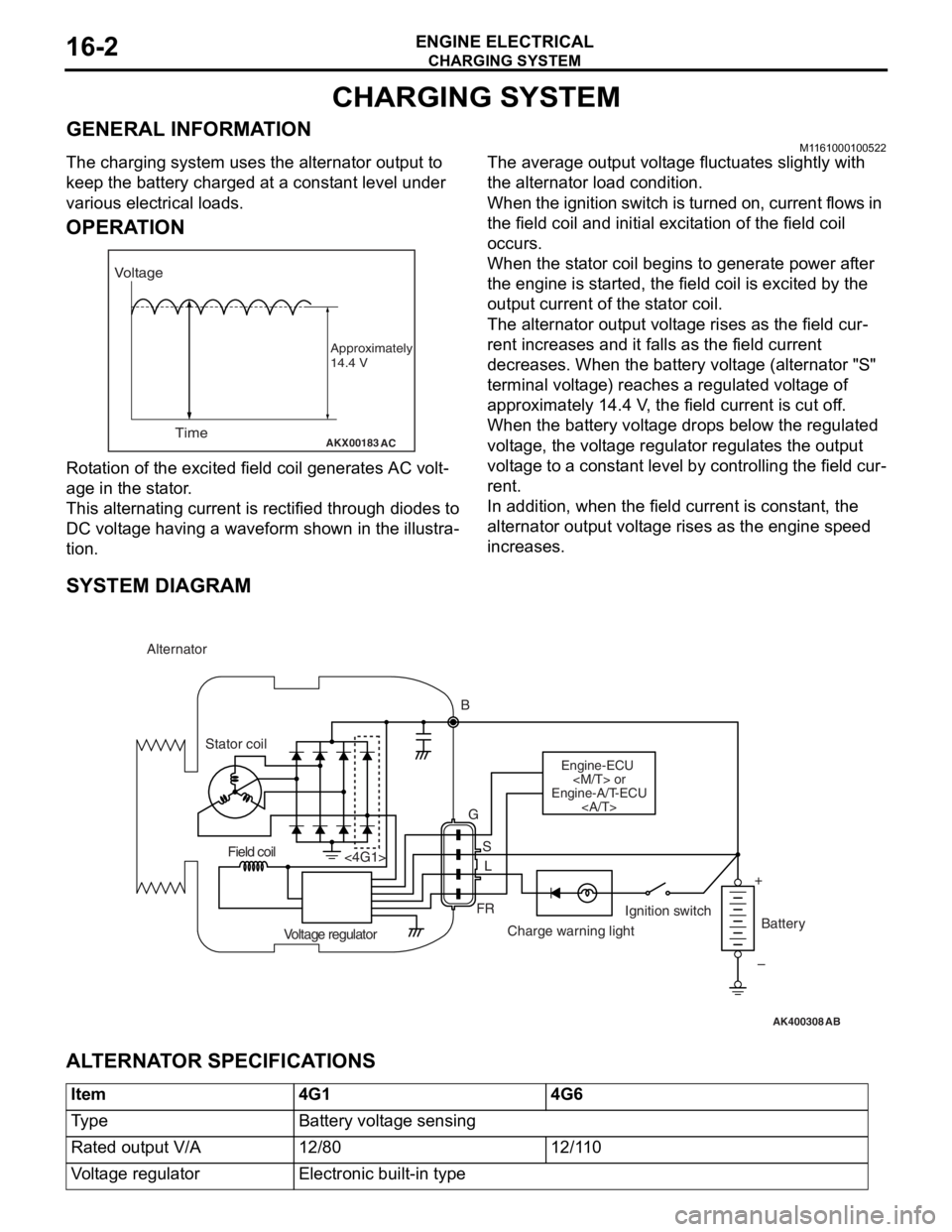
Rota tion of the excited fi eld coil gene rates AC volt-
age in the sta t or .
This alternatin g cur r ent is rectified throu gh diodes to
DC volt
age h a ving a waveform sh own in t he illustra
-
tion.
The average outpu t volt a ge flu c tua t es slightly with
the alternato
r load con d ition.
When the ign i tion switch is t u rned on, current flows in
the field coil and initial e
x cit a tion of the field coil
occurs.
When the st ator coil beg ins to gen erate p o wer af ter
the eng
ine is st a r ted, th e fie l d coil is excited by th e
output
curren t of th e st ator coil.
The alternator outpu t volt a ge rises as th e fie l d cur-
rent increa ses and it falls a s the field cu rrent
decre
ases. Whe n the b a ttery volt a ge (alternato r "S"
terminal volt
ag e) reaches a regulated volt ag e of
approximately 14.4
V , the field current is cut o f f.
When th
e batte ry volt age drop s be low the regulated
volt
ag e, the volt ag e regulator re gulat es th e outp u t
volt
ag e to a const ant level by contro lling the field cur
-
rent.
In addition, when th e fie l d current is const a n t, the
altern
ator ou tput volt age rise s as the e ngine spe ed
increase
s .
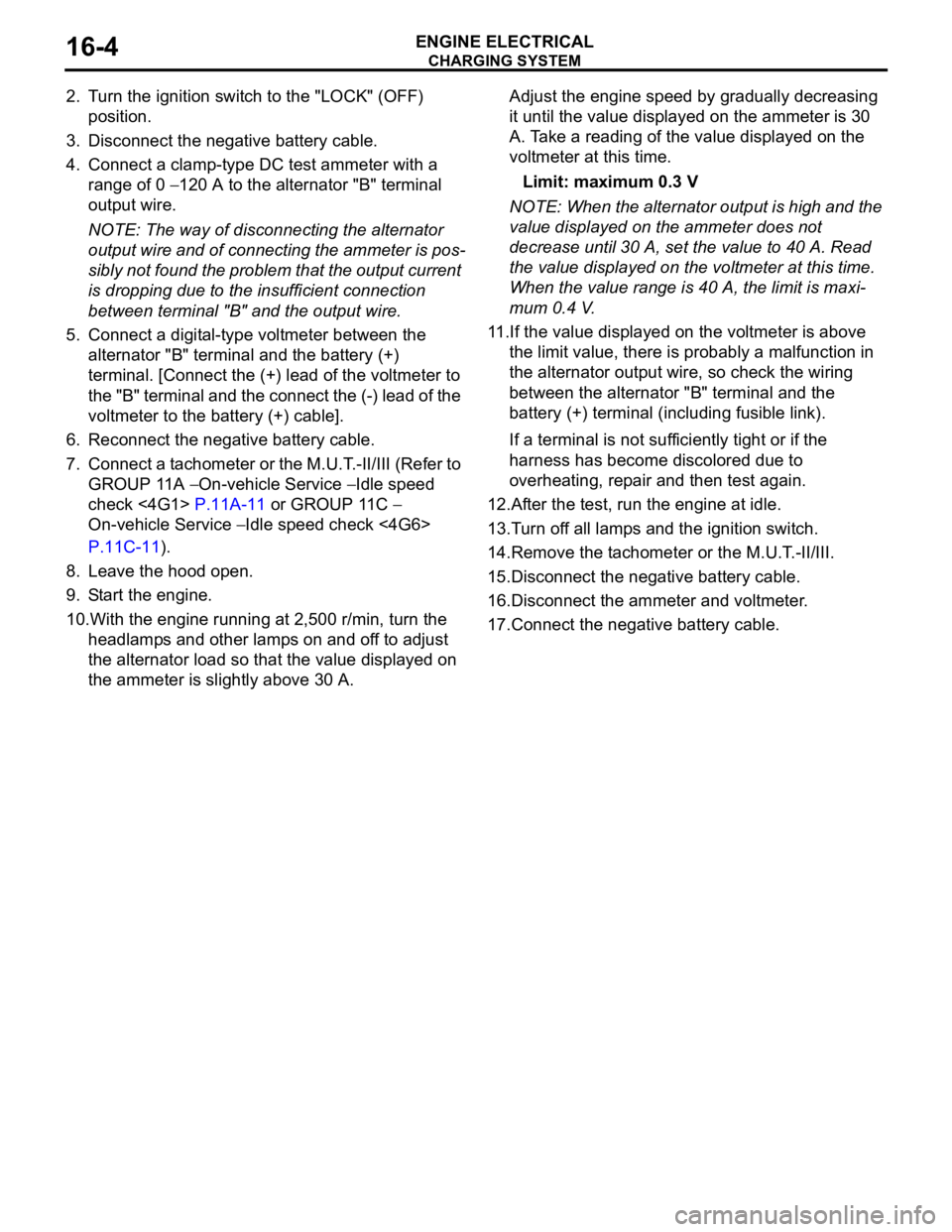
SYSTEM DIAGRAM
AK400308
Alternator
B
Stator coil
Engine-ECU
Engine-A/T-ECU
G
SL
FR
<4G1>
Voltage regulator Charge warning lightIgnition switch
Battery
Field coil
+
–
AB
AL TERNA T O R SPECIFICA T IONS
Item4G14G6
Ty p eBattery voltage sensing
Rated output V/A12/8012/110
Voltage regulatorElectronic built-in type
Page 65 of 800
CHARGING SYSTEM
ENGINE ELECTRICAL16-3
SERVICE SPECIFICATIONS
M1161000300258
ItemStandard valueLimit
Alternator output line voltage drop (at 30 A) V−maximum 0.3
Regulated voltage ambient
temperature at voltage regulator V−20°C14.2 − 15.4−
20°C13.9 − 14.9−
60°C13.4 − 14.6−
80°C13.1 − 14.5−
Output current−70 % of normal output current
SPECIAL TOOLM1161000600163
ToolNumberNameUse
MB991519Alterna t or test harn e ssChec king th e alt e rnator
("S" te rminal volt age )
ON-VEHICLE SERV ICE
ALTERNA T O R OUTPUT LINE VOL T AGE DROP TEST
M1161 0009 0034 6
AK203361AD
Alternator Ammeter (clamp-type)
Voltmeter (digital-type)
"B" terminal Battery
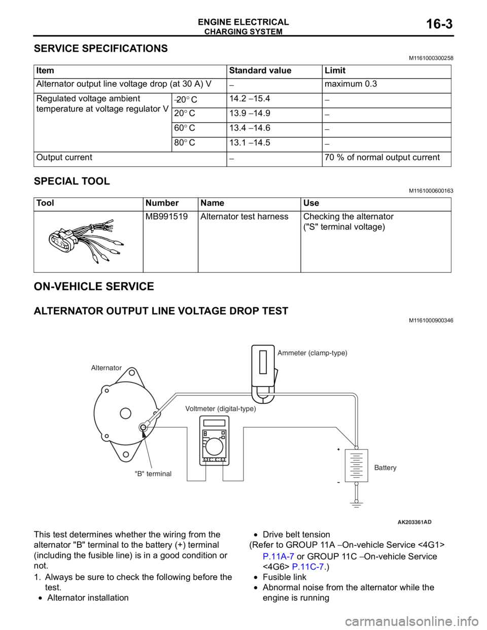
This test
determine s whethe r the wiring fro m th e
altern
ator "B" termina l to t he batt e ry (+) terminal
(including the
fusible line ) is in a good condition or
not.
1.Always b e su re to check the following b e fore th e
te st.
•Alternator inst allatio n
•Drive belt tension
(Ref er to GROUP 1 1 A − On-veh icle Service <4G1>
P.11A-7 or GROUP 1 1 C − On-vehicle Service
<4G6> P.11C-7.)
•Fusible link
•Abnormal noise from the altern ator while the
eng
ine is ru nning
Page 66 of 800
CHARGING SYSTEM
ENGINE ELECTRICAL16-4
2. Turn the ignition switch to the "LOCK" (OFF)
position.
3. Disconnect the negative battery cable.
4. Connect a clamp-type DC test ammeter with a
range of 0
− 120 A to the alternator "B" terminal
output wire.
NOTE: The way of disconnecting the alternator
output wire and of connecting the ammeter is pos
-
sibly not found the problem that the output current
is dropping due to the insufficient connection
between terminal "B" and the output wire.
5. Connect a digital-type voltmeter between the
alternator "B" terminal and the battery (+)
terminal. [Connect the (+) lead of the voltmeter to
the "B" terminal and the connect the (-) lead of the
voltmeter to the battery (+) cable].
6. Reconnect the negative battery cable.
7. Connect a tachometer or the M.U.T.-II/III (Refer to
GROUP 11A
− On-vehicle Service − Idle speed
check <4G1>
P.11A-11 or GROUP 11C −
On-vehicle Service − Idle speed check <4G6>
P.11C-11).
8. Leave the hood open.
9. Start the engine.
10.With the engine running at 2,500 r/min, turn the
headlamps and other lamps on and off to adjust
the alternator load so that the value displayed on
the ammeter is slightly above 30 A.
Adjust the engine speed by gradually decreasing
it until the value displayed on the ammeter is 30
A. Take a reading of the value displayed on the
voltmeter at this time.
Limit: maximum 0.3 V
NOTE: When the alternator output is high and the
value displayed on the ammeter does not
decrease until 30 A, set the value to 40 A. Read
the value displayed on the voltmeter at this time.
When the value range is 40 A, the limit is maxi
-
mum 0.4 V.
11.If the value displayed on the voltmeter is above
the limit value, there is probably a malfunction in
the alternator output wire, so check the wiring
between the alternator "B" terminal and the
battery (+) terminal (including fusible link).
If a terminal is not sufficiently tight or if the
harness has become discolored due to
overheating, repair and then test again.
12.After the test, run the engine at idle.
13.Turn off all lamps and the ignition switch.
14.Remove the tachometer or the M.U.T.-II/III.
15.Disconnect the negative battery cable.
16.Disconnect the ammeter and voltmeter.
17.Connect the negative battery cable.
Page 67 of 800
Page 68 of 800

CHARGING SYSTEM
ENGINE ELECTRICAL16-6
9. Check that the reading on the voltmeter is equal
to the battery voltage.
NOTE: If the voltage is 0 V, the cause is probably
an open circuit in the wire or fusible link between
the alternator "B" terminal and the battery (+) ter
-
minal.
10.Turn the light switch on to turn on headlamps and
then start the engine.
11.Immediately after setting the headlamps to high
beam and turning the heater blower switch to the
high revolution position, increase the engine
speed to 2,500 r/min and read the maximum
current output value displayed on the ammeter.
Limit: 70 % of normal current output
NOTE: .
•For the nominal current output, refer to the
Alternator Specifications.
•Because the current from the battery will soon
drop after the engine is started, the above step
should be carried out as quickly as possible in
order to obtain the maximum current output
value.
•The current output value will depend on the
electrical load and the temperature of the
alternator body.
•If the electrical load is small while testing, the
specified level of current may not be output
even though the alternator is normal. In such
cases, increase the electrical load by leaving
the headlamps turned on for some time to dis
-
charge the battery or by using the lighting sys-
tem in another vehicle, and then test again.
•The specified level of current also may not be
output if the temperature of the alternator body
or the ambient temperature is too high. In such
cases, cool the alternator and then test again.
12.The reading on the ammeter should be above the
limit value. If the reading is below the limit value
and the alternator output wire is normal, remove
the alternator from the engine and check the
alternator.
13.Run the engine at idle after the test.
14.Turn the ignition switch to the "LOCK" (OFF)
position.
15.Remove the tachometer or the M.U.T.-II/III.
16.Disconnect the negative battery cable.
17.Disconnect the ammeter and voltmeter.
18.Connect the negative battery cable.
Page 69 of 800
