component MITSUBISHI LANCER 2006 Workshop Manual
[x] Cancel search | Manufacturer: MITSUBISHI, Model Year: 2006, Model line: LANCER, Model: MITSUBISHI LANCER 2006Pages: 800, PDF Size: 45.03 MB
Page 8 of 800

GENERAL INFORMATION
ENGINE LUBRICATION12-2
GENERAL INFORMATION
M1121000100357
The lubrication method is a fully force-fed, full-flow fil-
tration type. The engine oil pump is a trochoid type
which is driven by the crankshaft <4G1>.The engine
oil pump is a gear type which is driven by the crank
-
shaft via the balancer timing belt <4G6>.
ENGINE OILS
Health Warning
Prolonged and repeated contact with mineral oil will
result in the removal of natural fats from the skin,
leading to dryness, irritation and dermatitis. In addi
-
tion, used engine oil contains potentially harmful con-
taminants which may cause skin cancer. Adequate
means of skin protection and washing facilities must
be provided.
Recommended Precautions
The most effective precaution is to adapt working
practices which prevent, as far as practicable, the
risk of skin contact with mineral oils, for example by
using enclosed systems for handling used engine oil
and by degreasing components, where practicable,
before handling them. Other precautions:
•Avoid prolonged and repeated contact with oils,
particularly used engine oils.
•Wear protective clothing, including impervious
gloves where practicable.
•Avoid contaminating clothes, particularly under-
pants, with oil.
•Do not put oily rags in pockets, the use of overalls
without pockets will avoid this.
•Do not wear heavily soiled clothing and
oil-impregnated foot-wear. Overalls must be
cleaned regularly and kept separate from per
-
sonal clothing.
•Where there is a risk of eye contact, eye protec-
tion should be worn, for example, chemical gog-
gles or face shields; in addition an eye wash
facility should be provided.
•Obtain first aid treatment immediately for open
cuts and wounds.
•Wash regularly with soap and water to ensure all
oil is removed, especially before meals (skin
cleansers and nail brushes will help). After clean
-
ing, the application of preparations containing
lanolin to replace the natur al skin oils is advised.
•Do not use petrol, kerosine, diesel fuel, gas oil,
thinners or solvents for cleaning skin.
•Use barrier creams, applying them before each
work period, to help the removal of oil from the
skin after work.
•If skin disorders develop, obtain medical advice
without delay.
SERVICE SPECIFICATION
M1121000300232
ItemStandard value
Oil pressure kPaat idle29 or more
at 3,500 r/min294 − 686
LUBRICANT
M1121000400433
ItemSpecification
Engine oil ACEA classificationA1, A2 or A3
Engine oil API classificationSG or higher
Engine oil quantity L4G1Oil filter0.3
To t a l3.3
4G6Oil filter0.3
To t a l4.3
Page 21 of 800
TROUBLESHOOTING
ENGINE COOLING14-7
•The engine-ECU
controls the cooling fan motor drive control
unit to activate the cooling fan motor (L.H.) and
the cooling fan motor (R.H.) <4G1 (Vehicles with
A/C)> or A/C condenser fan motor <4G6>.
TECHNICAL DESCRIPTION
•The cause could be a malfunction of the cooling
fan motor drive control unit power supply or earth
circuit.
•If the communication line wiring harness between
the cooling fan motor drive control unit and the
engine-ECU
short-circuited to earth, the cooling fan motor
(L.H.) and the cooling fan motor (R.H.) <4G1
(Vehicles with A/C)> or the A/C condenser fan
motor <4G6> will not rotate.
•The cause could also be a malfunction of the
cooling fan motor (L.H.).
•The cause could also be a malfunction of imput
signal from the A/C switch, the water temperature
sensor unit and the vehicle speed sensor
or the output shaft speed sensor to the
engine-ECU
•The cause could also be a malfunction of the
cooling fan motor drive control unit or the
engine-ECU
TROUBLESHOOTING HINTS
•Malfunction of fusible link (2)
•Malfunction of fan control relay
•Malfunction of cooling fan motor (L.H.)
•Malfunction of cooling fan motor drive control unit
•Malfunction of engine-ECU
engine-A/T-ECU
•Damaged wiring harness or connector
DIAGNOSIS
STEP 1. Check the cooling fan motor (L.H.).
Refer to P.14-24.
Q: Is the cooling fan motor (L.H.) in good condition?
YES : Go to Step 2 .
NO : Replace the cooling fan motor (L.H.) (Refer
to
P.14-33) <4G1> (Refer to P.14-35)
<4G6>. Then go to Step 24 .
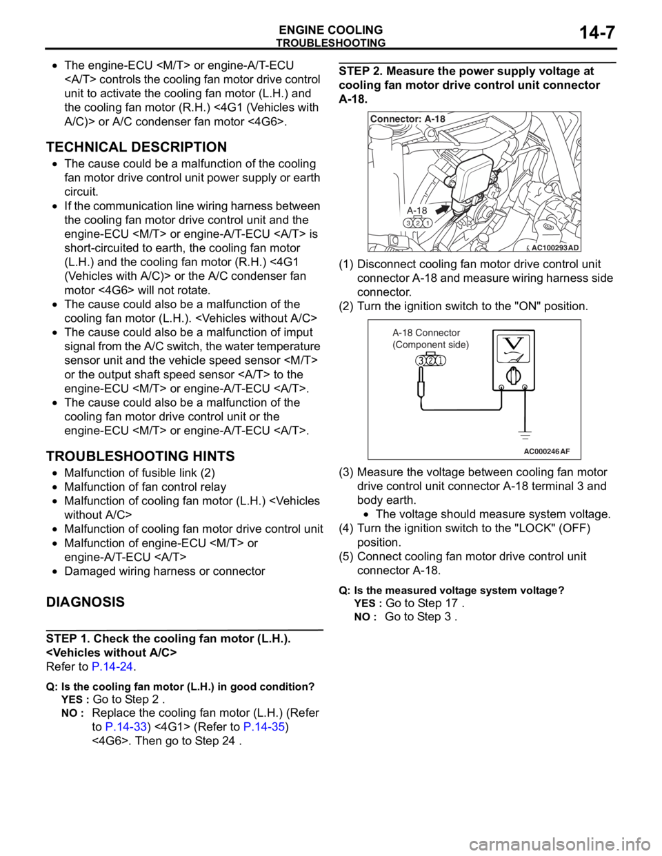
STEP 2. Measure the power supply voltage at
cooling fan motor drive control unit connector
A-18.
AC100293
A-18
321
Connector: A-18
AD
(1)D isconn ect cooling f an motor drive contro l unit
conne ctor A-18 a nd measure wirin g har ness side
connector .
(2)T urn t he ig nition switch t o the "ON" positio n.
AC000246AF
A-18 Connector
(Component side)
(3)M easu r e the volt age between cooling fan motor
drive control unit con nect o r A-18 te rmin al 3 a nd
bod y ea rth.
•The voltage shou ld measu r e syste m volt age.
(4)T urn t he ig nition switch t o the "L OCK" (OF F )
position.
(5)C onne ct cooling fa n mot o r drive control unit
connector A-18.
Q:Is t h e mea s ure d volt a g e sy ste m v o lt ag e?
YES : Go to S t ep 1 7 .
NO : Go to S t ep 3 .
Page 105 of 800
IGNITION SYSTEM
ENGINE ELECTRICAL16-43
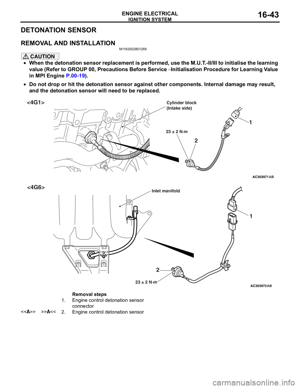
DETONATION SENSOR
REMOVAL AND INSTALLATION
M1163002801269
CAUTION
•When the detonation sensor replacement is performed, use the M.U.T.-II/III to initialise the learning
value (Refer to GROUP 00, Precautions Before Service
− Initialisation Procedure for Learning Value
in MPI Engine
P.00-19).
•
AC303971
2 1
23 ± 2 N·m
AB
<4G1>Cylinder block
(Intake side)
AC303972
2 1
23 ± 2 N·mAB
<4G6>Inlet manifold
Removal steps
1.Engine control detonation sensor
connector
<>>>A<<2.Engine control detonation sensor
Do not drop or hit the detonation sensor against other components. Internal damage may result,
and the detonation sensor will need to be replaced.
Page 107 of 800
17-1
GROUP 17
ENGINE AND
EMISSION
CONTROL
CONTENTS
ENGINE CONTROL . . . . . . . . . .17-2
GENERAL INFORMATION . . . . . .17-2
SERVICE SPECIFICATIONS. . . . .17-2
ON-VEHICLE SERVICE. . . . . . . . .17-2
ACCEL CABLE CHECK AND
ADJUSTMENT . . . . . . . . . . . . . . . . . . . . 17-2
ACCELERATOR CABLE AND
PEDAL . . . . . . . . . . . . . . . . . . . . . .17-3
REMOVAL AND INSTALLATION . . . . . 17-3
EMISSION CONTROL MPI . . . .17-4
GENERAL INFORMATION . . . . . .17-4
EMISSION CONTROL DEVICE
REFERENCE TABLE . . . . . . . . . .17-4
SERVICE SPECIFICATION(S) . . .17-5
VACUUM HOSE. . . . . . . . . . . . . . .17-5
VACUUM HOSE PIPING DIAGRAM . . . 17-5
VACUUM CIRCUIT DIAGRAM . . . . . . . 17-7
VACUUM HOSE CHECK. . . . . . . . . . . . 17-7
VACUUM HOSE INSTALLATION . . . . . 17-8
CRANKCASE EMISSION CONTROL
SYSTEM . . . . . . . . . . . . . . . . . . . . .17-8
GENERAL INFORMATION (CRANKCASE
EMISSION CONTROL SYSTEM) . . . . . 17-8
COMPONENT LOCATI ON (CRANKCASE
EMISSION CONTROL SYSTEM) . . . . . 17-9
POSITIVE CRANKCASE VENTILATION SYSTEM
CHECK . . . . . . . . . . . . . . . . . . . . . . . . . 17-9
POSITIVE CRANKCASE VENTILATION (PCV)
VALVE CHECK . . . . . . . . . . . . . . . . . . . 17-9
EVAPORATIVE EMISSION CONTROL
SYSTEM . . . . . . . . . . . . . . . . . . . . .17-9
GENERAL INFORMATION (EVAPORATIVE
EMISSION CONTROL SYSTEM) . . . . . 17-9
COMPONENT LOCATION (EVAPORATIVE
EMISSION CONTROL SYSTEM) . . . . . 17-10
PURGE CONTROL SYSTEM CHECK . . 17-10
PURGE PORT VACUUM CHECK . . . . . 17-11
PURGE CONTROL SOLENOID VALVE
CHECK . . . . . . . . . . . . . . . . . . . . . . . . . . 17-11
FUEL VAPOUR CANISTER REMOVAL
AND INSTALLATION . . . . . . . . . . . . . . . 17-12
EXHAUST GAS RECIRCULATION
(EGR) SYSTEM . . . . . . . . . . . . . . .17-12
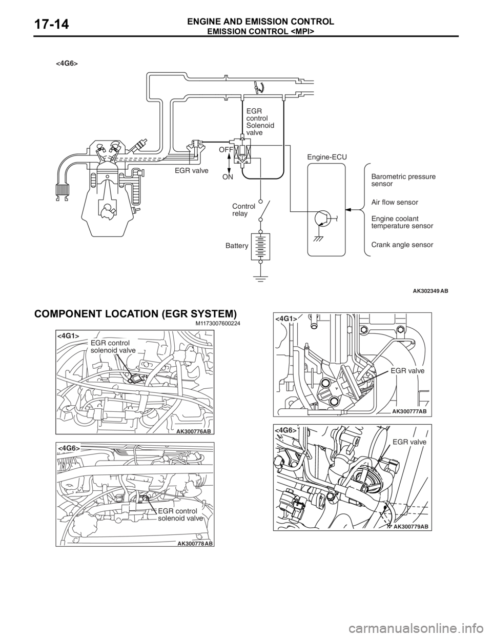
GENERAL INFORMATION
(EGR SYSTEM) . . . . . . . . . . . . . . . . . . . 17-12
COMPONENT LOCATION
(EGR SYSTEM) . . . . . . . . . . . . . . . . . . . 17-14
EGR SYSTEM CHECK . . . . . . . . . . . . . 17-15
EGR VALVE CHECK . . . . . . . . . . . . . . . 17-15
EGR PORT VACUUM CHECK <4G1>. . 17-16
EGR PORT VACUUM CHECK <4G6>. . 17-16
EGR CONTROL SOLENOID VALVE
CHECK <4G1> . . . . . . . . . . . . . . . . . . . . 17-16
EGR CONTROL SOLENOID VALVE
CHECK <4G6> . . . . . . . . . . . . . . . . . . . . 17-17
EXHAUST GAS RECIRCULATION (EGR)
VALVE REMOVAL AND I
NSTALLATION . . . . . . . . . . . . . . . . . . . . 17-18
CATALYTIC CONVERTER . . . . . .17-19
REMOVAL AND INSTALLATION
<4G1, 4G6-M/T> . . . . . . . . . . . . . . . . . . 17-19
REMOVAL AND INSTALLATION
<4G6-A/T> . . . . . . . . . . . . . . . . . . . . . . . 17-19
Page 110 of 800

EMISSION CONTROL
ENGINE AND EMISSION CONTROL17-4
INSTALLATION SERVICE POINT
>>A<< ACCEL PEDAL PAD INSTALLA-
TION
CAUTION
To prevent damages to the accelerator pedal pad,
warm the thumb area of the accelerator pedal
pad with a dryer, etc. prior to assembling it.
NOTE: If it is difficult to assemble, apply soapy water
to the thumb area to enhance the assembling proc
-
ess.
EMISSION CONTROL
GENERAL INFORMATION
M1173000100370
The emission control system consists of the following
subsystems:
•Crankcase emission control system
•Evaporative emission control system
•
ItemsNameSpecification
Crankcase emission control
systemPositive crankcase ventilation
(PCV) valveVariable flow type
(Purpose: HC reduction)
Evaporative emission control
systemCanister
Purge control solenoid valve
Equipped
Duty cycle type solenoid valve
(Purpose: HC reduction)
Exhaust emission control systemAir-fuel ratio control device - MPI
systemOxygen sensor feedback type
(Purpose: CO, HC, NOx reduction)
Exhaust gas recirculation system
•EGR valve
•EGR control solenoid valve
Equipped
Single type
Duty cycle type solenoid valve
(Purpose: NOx reduction)
Catalytic converterMonolith type
(Purpose: CO, HC, NOx reduction)
Exhaust emission control system
EMISSION CONTROL DEVICE
REFERENCE TABLE
M1173006600135
Related partsCrankcase
emission
control
systemEvaporative
emission
control
systemAir/fuel ratio
control
systemCatalytic
converterExhaust gas
recirculation
system
PCV valve×
Purge control solenoid valve×
MPI system component××
Catalytic converter×
EGR valve×
EGR control solenoid valve×
7.Accelerator control equip bushing
8.Accelerator pedal arm return spring
9.Accelerator pedal arm stopper
10.Accelerator pedal arm bracket
11 .Accelerator pedal arm
>>A<<12.Accelerator pedal pad
13.Accelerator pedal arm stopper
Accelerator pedal assembly
removal steps (Continued)
Page 115 of 800
EMISSION CONTROL
ENGINE AND EMISSION CONTROL17-9
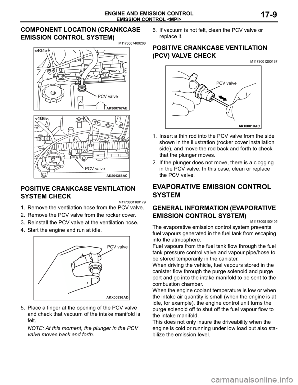
COMPONENT LOCATION (CRANKCASE
EMISSION CONTROL SYSTEM)
M1173007400208
AK300767
<4G1>
AB
PCV valve
AK204366
<4G6>
AC
PCV valve
POSITIVE CRANKCASE VENTILATION
SYSTEM CHECK
M11 7300 1 1 0017 9
1.Remove the ventilatio n hose from the PCV valve.
2.Remove the PCV valve from t he rocker cove r .
3.Reinst all the PCV valve at the ven t ila tion h o se.
4.S t art the engin e and run at idle .
AKX00336
PCV valve
AD
5.Pla c e a fing er at the open ing o f the PCV va lve
an d ch eck that vacu um o f the int a ke manifold is
fe lt.
NOTE: At this mo men t, the p l unge r in t he PCV
valve mo ves back an d forth.
6.If vacuum is not felt, clean t he PCV valve o r
re place it.
POSITIVE CRANKCASE VENTILA TION
(
P CV) V A L VE CHECK
M1173 0012 0018 7
AK100010
PCV valve
AC
1.In sert a thin rod in to the PCV valve from the side
shown in the illu strat i on (ro cke r cover in st allation
side) , and move the ro d back an d forth to ch eck
th at the plung er mo ves.
2.If the plunger does not move , there is a clo ggin g
in the PCV valve. In th is case, clean o r repla c e
th e PCV valve.
EVAPORA T IVE EMISSION CONTROL
SYSTEM
GENERAL INFORMA T ION (EV A PORA TIVE
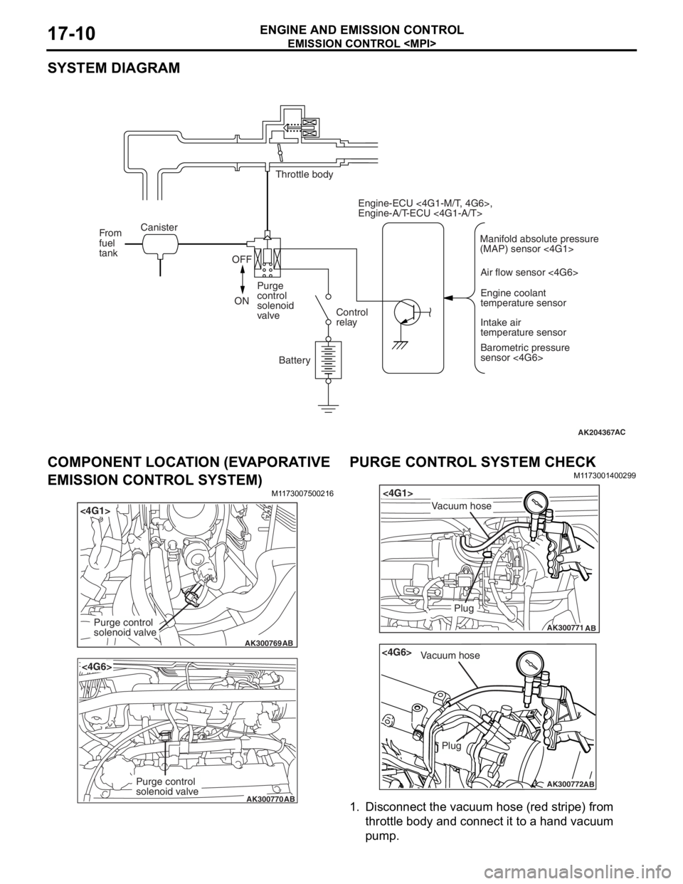
EMISSION CONTROL SYSTEM)
M1173 0051 0040 5
The evaporat ive emission contro l syste m pre v ent s
f
uel vapours generat ed in t he fuel t ank from escaping
into t
he atmosp here.
Fuel vapours fro m the fuel t a n k flow throug h the f uel
t
a n k pre ssu re co ntrol valve an d vap our pipe/ho se to
be st
ored te mpora r ily in t he ca nister .
When dr iving the veh i cle, fue l va pours stor ed in the
canister
flow thro ugh th e purge solenoid and purge
port an
d go into the int a ke ma nifold to b e sen t to th e
combust
i on chamber .
When the eng ine co ola n t te mp eratu r e is low o r when
the int
a ke air q uantity is small (wh en the engine is at
idle
, for example), t he eng ine contro l unit turns the
purge sole
noid of f to shu t of f the fue l va pour flow to
the in
t a ke manif o ld.
This does not on ly insure the driveability when t he
engin
e is cold or runn ing und er low load b u t also st a
-
bilize the emissio n level.
Page 116 of 800
EMISSION CONTROL
ENGINE AND EMISSION CONTROL17-10
SYSTEM DIAGRAM
AK204367AC
Throttle body
Canister
From
fuel
tank
OFF
ON Purge
control
solenoid
valve
Control
relay
Battery Engine-ECU <4G1-M/T, 4G6>,
Engine-A/T-ECU <4G1-A/T>
Air flow sensor <4G6>Engine coolant
temperature sensor
Intake air
temperature sensor
Barometric pressure
sensor <4G6>
Manifold absolute pressure
(MAP) sensor <4G1>
COMPONENT LOCA
TION (EV A PORA TIVE
EMISSION CONTROL SYSTEM)
M1173 0075 0021 6
AK300769
<4G1>
AB
Purge control
solenoid valve
AK300770
<4G6>
AB
Purge control
solenoid valve
PURGE CONTROL SYSTEM CHECK
M1173 0014 0029 9
AK300771
<4G1>
AB
Plug
Vacuum hose
AK300772
<4G6>
AB
Plug
Vacuum hose
1.Disco nnect the vacu um h o se (re d str i pe) fro m
th rottle body and conne ct it to a h and vacu um
pu m p .
Page 120 of 800
AK302349AB
<4G6>EGR
control
Solenoid
valve
EGR valve OFF
ON
Control
relay
Battery Engine-ECU
Barometric pressure
sensor
Air flow sensor
Engine coolant
temperature sensor
Crank angle sensor
EMISSION CONTROL
ENGINE AND E M ISSION CON T ROL17-14
COMPONENT LOCATION (EGR SYSTEM)
M1173 0076 0022 4
AK300776
<4G1>
AB
EGR control
solenoid valve
AK300778
<4G6>
AB
EGR control
solenoid valve
AK300777
<4G1>
AB
EGR valve
AK300779AB
<4G6>
EGR valve
Page 166 of 800
TROUBLESHOOTING
WHEEL AND TYRE31-4
WHEEL BALANCE ACCURACY
M1311001700247
PURPOSE
This section contains tips and procedures for achiev-
ing accurate wheel balance. Steering wheel vibration
and/or body shake can result if any of these proce
-
dures are not carefully observed.
1. Wheels and tyres must be properly mounted on a balancer in order to achieve correct balance.
Centring the wheel on the shaft of the balancer is
essential for proper mounting.
2. Off-the-car wheel balancers must be calibrated periodically to ensure good balancing results. An
inaccurately calibrated balancer could cause
unnecessary replacement of tyres, shocks,
suspension components, or steering components.
Check your balancer's calibration approximately
every 100 balances. Your wheel balancer's instruc
-
tion manual should include calibration procedures. If
the calibration procedures specifically for your bal
-
ancer are missing, use the generic steps in this sec-
tion for zero calibration, static balance, and dynamic
balance checks. The wheel balancer calibration
checks are also described in the flowchart. (Refer to
P.31-6).
PROCEDURE
1. Confirm that the balancer's cone and the wheel
mounting cone are undamaged and free of dirt
and rust.
2. On this vehicle, the wheel's centre hole on the hub side has a chamfered edge. Use a
back-mounting cone on your wheel balancer to
centre the wheel on the balancer shaft.
3. Install a wheel mounting cone. The appropriate size cone for this vehicle is 67.0 mm.
4. Before balancing the wheel, remove any wheel weights from both sides. Also check both sides for
any damage.
5. When installing wheel weights, hammer them at a straight (not diagonal) angle.
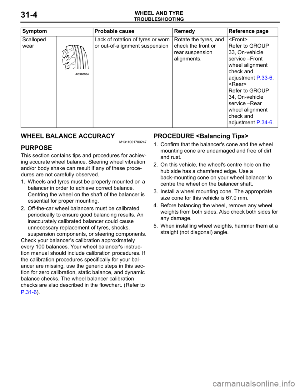
Scalloped
wear
ACX00934
Lack of rot a tio n of tyres or worn
or out-of-a
lign m ent suspensionRota te th e tyre s, an d
check the f
r ont or
rea
r suspension
alignment
s.
Refer to GROUP
33
, On -vehicle
serv
ic e
− Front
whee
l alignment
check and
ad
justmen t
P.33-6.
Refer to GROUP
34
, On -vehicle
serv
ic e
− Rear
whee
l alignment
check and
ad
justmen t
P.34-6.
Sy mptom P robable cause Reme dy Referen ce p a g e
Page 183 of 800
33-1
GROUP 33
FRONT
SUSPENSION
CONTENTS
GENERAL INFORMATIO N . . . . . . . .33-2
SERVICE SPECIFICATIONS . . . . . . .33-3
LUBRICANT . . . . . . . . . . . . . . . . . . . .33-3
SPECIAL TOOLS . . . . . . . . . . . . . . . .33-4
ON-VEHICLE SERVICE . . . . . . . . . . .33-6
FRONT WHEEL ALIGNMENT CHECK AND
ADJUSTMENT . . . . . . . . . . . . . . . . . . . . . . 33-6
LOWER ARM BALL JOINT AXIAL PLAY
CHECK . . . . . . . . . . . . . . . . . . . . . . . . . . . . 33-7
LOWER ARM BALL JOINT COVER
CHECK . . . . . . . . . . . . . . . . . . . . . . . . . . . . 33-7
STRUT ASSEMBLY . . . . . . . . . . . . . .33-7
REMOVAL AND INSTALLATION . . . . . . . . 33-7
INSPECTION. . . . . . . . . . . . . . . . . . . . . . . . 33-7
DISASSEMBLY AND REASSEMBLY . . . . . 33-8
INSPECTION. . . . . . . . . . . . . . . . . . . . . . . . 33-10
LOWER ARM . . . . . . . . . . . . . . . . . . .33-11
REMOVAL AND INSTALLATION . . . . . . . . 33-11
INSPECTION. . . . . . . . . . . . . . . . . . . . . . . . 33-12
LOWER ARM BALL JOINT COVER
REPLACEMENT . . . . . . . . . . . . . . . . . . . . . 33-12
LOWER ARM BUSHING (REAR)
REPLACEMENT . . . . . . . . . . . . . . . . . . . . . 33-13
STABILIZER BAR. . . . . . . . . . . . . . . .33-14
REMOVAL AND INSTALLATION . . . . . . . . 33-14
INSPECTION. . . . . . . . . . . . . . . . . . . . . . . . 33-16
WARNINGS REGARDING SERVICING OF SUPPLEMENTAL RESTRAINT SYSTEM (SRS) EQUIPPED VEHICLES
WARNING
•Improper service or maintenance of any component of the SRS, or any SRS-related component, can lead to
personal injury or death to service personnel (from inad vertent firing of the air bag) or to the driver and
paassenger (from rendering the SRS inoperative).
•Service or maintenance of any SRS component or SRS-related component must be performed only at an
authorized MITSUBISHI dealer.
•MITSUBISHI dealer personnel must thoroughly review this manual, and especially its GROUP 52B - Supplemental
Restraint System (SRS) before beginning any service or maintenance of any component of the SRS or any
SRS-related component.
NOTE
The SRS includes the following components: SRS air bag control unit, SRS warning light, front impact sensors, air bag module,
clock spring, and interconnecting wiring. Other SRS-related components (that may have to be removed/installed in connection
with SRS service or maintenance) are indicated in the table of contents by an asterisk (*).