door lock MITSUBISHI LANCER 2006 Workshop Manual
[x] Cancel search | Manufacturer: MITSUBISHI, Model Year: 2006, Model line: LANCER, Model: MITSUBISHI LANCER 2006Pages: 800, PDF Size: 45.03 MB
Page 274 of 800

42-2
TROUBLESHOOTING . . . . . . . . . .42-26
ON-VEHICLE SERVICE. . . . . . . . .42-27
DOOR FIT ADJUSTMENT. . . . . . . . . . . 42-27
DOOR WINDOW GLASS
ADJUSTMENT . . . . . . . . . . . . . . . . . . . . 42-28
GLASS SLIDING MECHANISM CHECK
AND ADJUSTMENT . . . . . . . . . . . . . . . 42-28
POWER WINDOW OPERATING
CURRENT CHECK . . . . . . . . . . . . . . . . 42-28
POWER WINDOW RELAY CHECK . . . 42-29
CIRCUIT BREAKER (INCORPORATED
IN THE POWER WINDOW MOTOR)
INSPECTION . . . . . . . . . . . . . . . . . . . . . 42-29
POWER WINDOW CHECK . . . . . . . . . . 42-29
CENTRAL DOOR LOCKING SYSTEM
INSPECTION . . . . . . . . . . . . . . . . . . . . . 42-29
DOOR OUTSIDE HANDLE PLAY
CHECK . . . . . . . . . . . . . . . . . . . . . . . . . 42-29
DOOR INSIDE HANDLE PLAY
ADJUSTMENT . . . . . . . . . . . . . . . . . . . . 42-30
DOOR ASSEMBLY . . . . . . . . . . . .42-31
REMOVAL AND INSTALLATION . . . . . 42-31
INSPECTION . . . . . . . . . . . . . . . . . . . . . 42-32
DOOR GLASS AND REGULATOR42-32
REMOVAL AND INSTALLATION . . . . . 42-32
INSPECTION . . . . . . . . . . . . . . . . . . . . . 42-34
DOOR HANDLE AND LATCH . . . .42-36
REMOVAL AND INSTALLATION . . . . . 42-36
INSPECTION . . . . . . . . . . . . . . . . . . . . . 42-37
WINDOW GLASS RUNCHANNEL
AND DOOR OPENING
WEATHERSTRIP . . . . . . . . . . . . . .42-39
REMOVAL AND INSTALLATION . . . . . 42-39
TRUNK LID . . . . . . . . . . . . . . . .42-41
SPECIAL TOOL . . . . . . . . . . . . . . .42-41
ON-VEHICLE SERVICE. . . . . . . . .42-41
TRUNK LID ADJUSTMENT . . . . . . . . . . 42-41
ADJUSTMENT OF CLEARANCE
AROUND TRUNK LID . . . . . . . . . . . . . . 42-42
TRUNK LID STRIKER ADJUSTMENT . 42-42
TRUNK LID HEIGHT ADJUSTMENT . . 42-42
TRUNK LID . . . . . . . . . . . . . . . . . . .42-43
REMOVAL AND INSTALLATION . . . . . . 42-43
INSPECTION . . . . . . . . . . . . . . . . . . . . . 42-45
TAILGATE . . . . . . . . . . . . . . . . 42-46
SERVICE SPECIFICATIONS . . . . .42-46
SEALANTS . . . . . . . . . . . . . . . . . . .42-46
SPECIAL TOOL . . . . . . . . . . . . . . .42-46
TROUBLESHOOTING . . . . . . . . . .42-47
ON-VEHICLE SERVICE . . . . . . . . .42-47
TAILGATE FIT ADJUSTMENT. . . . . . . . 42-47
TAILGATE HANDLE PLAY CHECK . . . . 42-47
TAILGATE . . . . . . . . . . . . . . . . . . .42-48
REMOVAL AND INSTALLATION . . . . . . 42-48
TAILGATE HANDLE AND
LATCH . . . . . . . . . . . . . . . . . . . . . .42-50
REMOVAL AND INSTALLATION . . . . . . 42-50
INSPECTION . . . . . . . . . . . . . . . . . . . . . 42-51
KEYLESS ENTRY SYSTEM . . 42-51
SERVICE SPECIFICATIONS . . . . .42-51
SPECIAL TOOLS . . . . . . . . . . . . . .42-52
TROUBLESHOOTING . . . . . . . . . .42-53
ON-VEHICLE SERVICE . . . . . . . . .42-53
KEYLESS ENTRY SYSTEM CHECK. . . 42-53
KEYLESS ENTRY SYSTEM TIMER
LOCK FUNCTION INSPECTION . . . . . . 42-53
ENABLING/DISABLING THE
ANSWERBACK FUNCTION . . . . . . . . . 42-53
HOW TO REGISTER SECRET CODE . 42-55
TRANSMITTER. . . . . . . . . . . . . . . .42-58
DISASSEMBLY AND REASSEMBLY . . 42-58
INSPECTION . . . . . . . . . . . . . . . . . . . . . 42-59
Page 297 of 800
AC304849AB
Dual lock fastener
Flange convex at the tailgate flange
DOOR
BO
D Y42-25
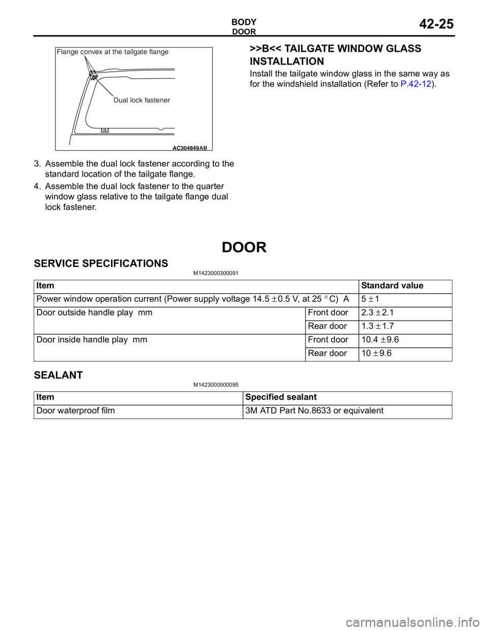
3.Assemble the dua l lo ck faste ner accord ing t o the
st a ndard loca tion of the t a ilgat e flan ge.
4.Assemble the dua l lo ck faste ner to t he qua rter
win dow gla ss relative to the t a ilgate flan ge dua l
lock fastener .
>>B<< TA ILGA TE WINDOW GLASS
INST
ALLA TION
Install the t a ilgat e window g l ass in the same wa y as
for the
windsh i eld inst a lla tion ( R ef er to
P.42-12).
DOOR
SER V ICE SPECIFICA T IONS
M14230003 0009 1
ItemStandard value
Power window operation current (Power supply voltage 14.5 ± 0.5 V, at 25 °C) A5 ± 1
Door outside handle play mmFront door2.3 ± 2.1
Rear door1.3 ± 1.7
Door inside handle play mmFront door10.4 ± 9.6
Rear door10 ± 9.6
SEALANT
M14230005 0009 5
ItemSpecified sealant
Door waterproof film3M ATD Part No.8633 or equivalent
Page 299 of 800
DOOR
BODY42-27
ON-VEHICLE SERVICE
DOOR FIT ADJUSTMENT
M1423001100175
CAUTION
•Attach protection tape to the fender and door
edges where the hinge is installed.
•Do not rotate special tool door adjusting
wrench (MB991164) with a torque of over 98
N
⋅m
AC000592
MB990900
or
MB991164
AB
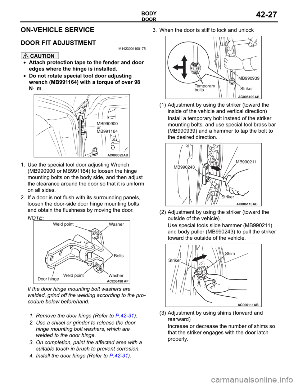
1. Use the special tool door adjusting Wrench (MB990900 or MB991164) to loosen the hinge
mounting bolts on the body side, and then adjust
the clearance around the door so that it is uniform
on all sides.
2. If a door is not flush with its surrounding panels,
loosen the door-side d oor hinge mounting bolts
and obtain the flushness by moving the door.
NOTE:
AC206498
Washer Bolts
Washer
Door hinge
AF
Weld point
Weld point
If the door hinge mounting bolt washers are
welded, grind off the welding according to the pro
-
cedure below beforehand.
.
1. Remove the door hinge (Refer to P.42-31).
2. Use a chisel or grinder to release the door
hinge mounting bolt washers, which are
welded to the door hinge.
3. On completion, paint the affected area with a suitable touch-in brush to prevent corrosion.
4. Install the door hinge (Refer to P.42-31).
3. When the door is stiff to lock and unlock
AC006109AB
Temporary
bolts Striker
MB990939
(1) Adjustment by using the striker (toward the
inside of the vehicle and vertical direction)
Install a temporary bolt instead of the striker
mounting bolts, and use special tool brass bar
(MB990939) and a hammer to tap the bolt to
the desired direction.
AC006110
Striker MB990211
MB990243
AB
(2) Adjustment by using the striker (toward the
outside of the vehicle)
Use special tools slide hammer (MB990211)
and body puller (MB990243) to pull the striker
toward the outside of the vehicle.
AC006111AB
Shim
Striker
(3) Adjustment by using shims (forward and rearward)
Increase or decrease the number of shims so
that the striker engages with the door latch
properly.
Page 301 of 800
DOOR
BODY42-29
3. If the operation current is outside the standard value, refer to GROUP 54B, Troubleshooting
P.54B-15, refer to GROUP 54C, Troubleshooting
P.54C-4.
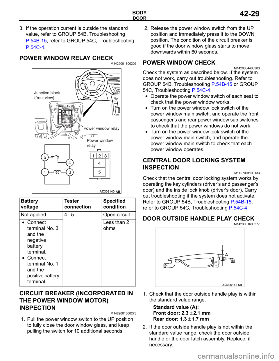
POWER WINDOW RELAY CHECKM1429001800202
AC305140
123
4
5
1 3
4
5
AB
Junction block
(front view)
Power window relayPower window
relay
Bat t ery
voltage
Teste r
co
nnectionSpecified
condition
Not applied4 − 5Ope n ci rcui t
•Connect
te
rmin al No. 3
an
d the
ne
gative
ba
ttery
te
rmin al.
•Connect
te
rmin al No. 1
an
d the
positive batt
e ry
te
rmin al.
Less than 2
ohms
CIRCUIT BREAKER (INCORPORA T ED IN
THE POW
E R W I NDOW MOT O R)
INSPECTION
M14290010 0027 3
1.Pull the p o wer windo w switch to th e UP position
to f u lly close the do or windo w g l ass, an d ke ep
pullin g the switch for 1 0 addition al secon d s.
2.Rele ase the power window switch from t he UP
position an d immediately pre ss it to t he DOW N
position. Th e con d ition of the circu i t brea ker is
goo d if t he doo r window g l ass st art s to mo ve
downward s with in 60 seconds.
POWER WI NDOW CHECKM14290044 0020 3
Check the system a s de scribed b e low . I f the system
does not work, car
r y out troublesh ootin g. Refer to
GROUP 54
B, T r ouble s hoo ting
P.54B-15 or GROUP
54C, T r oublesh ootin g P.54C-4.
•Operate the powe r wind ow switch of e a ch se at to
check that
the power window works.
•Tu rn o n the power wind ow lock switch of the
power wind
ow main swit ch, and ope rate the front
p
a ssenger's and rear power window su b switches
to check th
at the p o wer windo ws do n o t work.
•Tu rn o n the power wind ow lock switch of the
power
window main switch, and operate the
power
window main switch to check tha t each
power window
op erates.
CENTRAL DOOR LOCKING SYSTEM
INSPECTION
M142700 1 1 0013 3
Check that th e ce ntral door locking system wo rks by
op
er atin g th e key cylin de rs (d rive r ’ s an d p a sse n g e r ’ s
door) an
d the inside lock kno b (driver's door). Ca rry
out trou
bleshooting if the system does not activate.
Re
fer to GROUP 54B, T r ou bleshooting
P.54B-15,
refer to GROUP 54 C, T r o uble s hoo ting P.54C-4.
DOOR OUTSIDE HANDLE PL A Y CHECKM14230016 0027 7
AC006113
AB
A
1.Check t hat the door o u t s ide handle play is with in
th e st and ard va lue range.
St andard va lue (A):
Fron t door: 2.3 ± 2.1 m m
Rear door: 1.3 ± 1.7 mm
2. If the do or out side ha ndle play is not wit h in th e
st a ndard valu e rang e, ch eck the do or out side
h andle or the door latch assemb ly . Replace, if
ne c e ss a r y .
Page 308 of 800
DOOR
BODY42-36
DOOR HANDLE AND LATCH
REMOVAL AND INSTALLATION
M1423004600328
Pre-removal Operation
•Door Trim Removal (Refer to GROUP 52A, Door trim P.52A-17.)
Post-installation Operation
•Door Inside Handle Play Check (Refer to P.42-30.)
•Door Outside Handle Play Check (Refer to P.42-29.)
•Door Trim Installation (Refer to GROUP 52A, Door trim
P.52A-17.)
AC305110
5
5.0 ± 1.0 N·m
1
4
9
2
AB
4 5
2
3
8 7
5.0 ± 1.0 N·m
1
6
9
NN
89.0 ± 2.0 N·m 9.0 ± 2.0 N·m
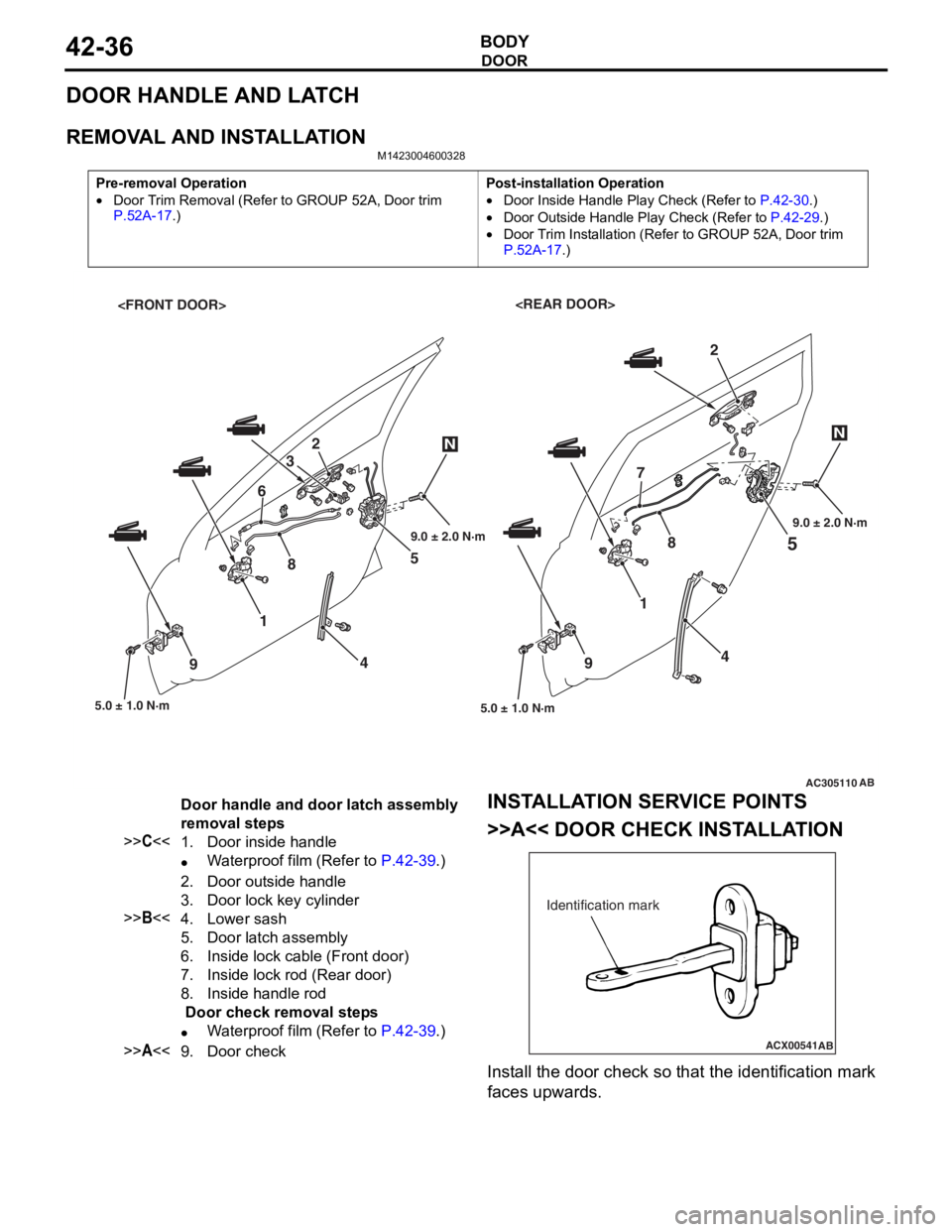
Door handle and door latch assembly
removal steps
>>C<<1.Door inside handle
•Waterproof film (Refer to P.42-39.)
2.Door outside handle
3.Door lock key cylinder
>>B<<4.Lower sash
5.Door latch assembly
6.Inside lock cable (Front door)
7.Inside lock rod (Rear door)
8.Inside handle rod
Door check removal steps
•Waterproof film (Refer to P.42-39.)
>>A<<9.Door check
INST
ALLA T ION SER VICE POINTS
>>A<< DOOR CHECK INST ALLA TION
ACX00541
Identification mark
AB
Install the d oor check so that th e ide n tification mark
faces upward
s .
Page 309 of 800
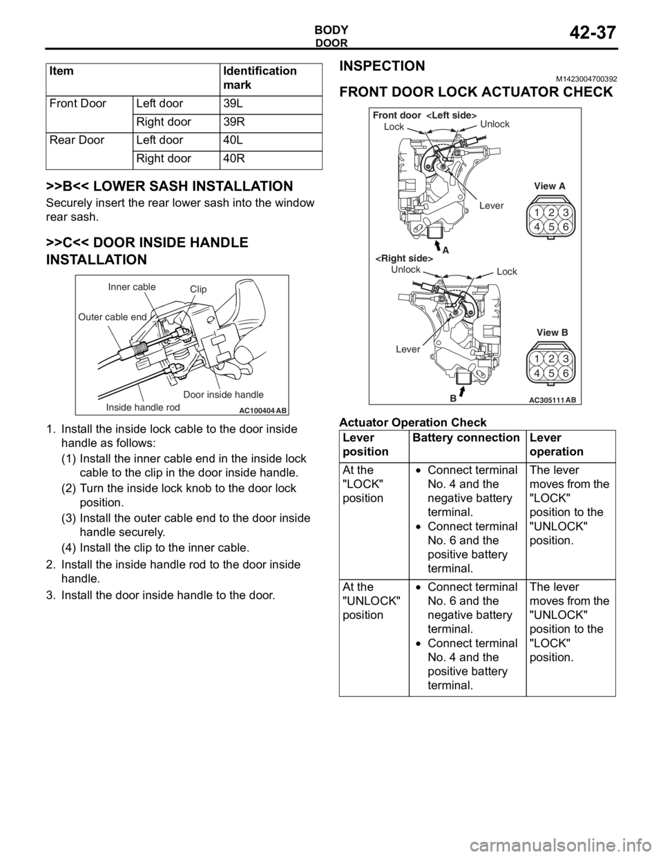
ItemIdentification
mark
Front DoorLeft door39L
Right door39R
Rear DoorLeft door40L
Right door40R
DOOR
BODY42-37
>>B<< LOWER SASH INSTALLATION
Securely insert the rear lower sash into the window
rear sash.
>>C<< DOOR INSIDE HANDLE
INSTALLATION
AC100404AB
Clip
Inner cable
Outer cable end
Inside handle rod Door inside handle
1.
In st all the inside lo ck cable to th e doo r inside
ha ndle as fo llo ws:
(1)I nst a ll the inne r cab l e en d in the in sid e lock
cab l e to the clip in th e door inside h andle .
(2)T urn the inside lock knob to the do or lock
positio n.
(3)I nst a ll the outer cable end to the door inside
hand le secure ly .
(4)I nst a ll the clip to the in ner cable .
2.In st all the inside han dle ro d to th e door inside
ha ndle .
3.In st all the do or inside handle to t he doo r .
INSPECTION
M14230047 0039 2
FRONT DOOR LOCK ACTUA T O R CHECK
42
53
6
1
4 2
53
6
1
AC305111B
A
AB
Lock
Unlock
View A
View B
Unlock
Lock
Front door
Lever
Ac tuator Op era t ion Check
Lever
positionBattery connectionLever
operation
At the
"LOCK"
position•Connect terminal
No. 4 and the
negative battery
terminal.
•Connect terminal
No. 6 and the
positive battery
terminal.
The lever
moves from the
"LOCK"
position to the
"UNLOCK"
position.
At the
"UNLOCK"
position•Connect terminal
No. 6 and the
negative battery
terminal.
•Connect terminal
No. 4 and the
positive battery
terminal.
The lever
moves from the
"UNLOCK"
position to the
"LOCK"
position.
Page 310 of 800
DOOR
BODY42-38
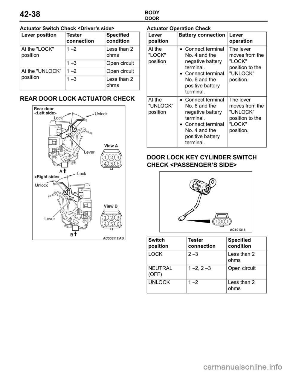
Actuator Switch Check
Lever positionTester
connectionSpecified
condition
At the "LOCK"
position1 − 2Less than 2
ohms
1 − 3Open circuit
At the "UNLOCK"
position1 − 2Open circuit
1 − 3Less than 2
ohms
REAR DOOR LOCK ACTUATOR CHECK
23
4 1
56
23
4 1
56
AC305112B
A
AB
Rear door
Lock Unlock
View A
View B
Unlock
Lock
Lever
Ac tuator Op era t ion Check
Lever
positionBattery connectionLever
operation
At the
"LOCK"
position•Connect terminal
No. 4 and the
negative battery
terminal.
•Connect terminal
No. 6 and the
positive battery
terminal.
The lever
moves from the
"LOCK"
position to the
"UNLOCK"
position.
At the
"UNLOCK"
position•Connect terminal
No. 6 and the
negative battery
terminal.
•Connect terminal
No. 4 and the
positive battery
terminal.
The lever
moves from the
"UNLOCK"
position to the
"LOCK"
position.
DOOR LOCK KEY CYLINDER SWITCH
CHECK
AC101318
3
2
1
Switch
positionTester
connectionSpecified
condition
LOCK2 − 3Less than 2
ohms
NEUTRAL
(OFF)1 − 2, 2 − 3Open circuit
UNLOCK1 − 2Less than 2
ohms
Page 313 of 800
Page 325 of 800
KEYLESS ENTRY SYSTEM
BODY42-53
TROUBLESHOOTING
M1428000700287
The keyless entry system is controlled by the Smart
Wiring System (SWS). For troubleshooting, refer to
GROUP 54B, Troubleshooting
P.54B-15 or GROUP
54C, Troubleshooting P.54C-4.
ON-VEHICLE SERVICE
KEYLESS ENTR Y SYSTEM CHECKM1428001400096
Check the system as described below. If the system
does not work, carry out troubleshooting. Refer to
GROUP 54B, Troubleshooting
P.54B-15, refer to
GROUP 54C, Troubleshooting P.54C-4.
•Operate the transmitter to check that the doors
and tailgate can be locked and unlocked.
•Operate the transmitter to check that the answer-
back function works in response to door and tail-
gate
NOTE: The adjustment function allows you to
change the answerback setting as follows. Prior
to that check, confirm which setting is activated.
.
•The hazard warning lamps flash twice when
locked and once when unlocked. The room
lamp flashes twice when locked and illumi
-
nates for 15 seconds when unlocked.
•The hazard warning lamps do not flash when
locked and flash once when unlocked. The
room lamp flashes twice when locked and illu
-
minates for 15 seconds when unlocked.
•The hazard warning lamps flash twice when
locked and do not flash when unlocked. The
room lamp flashes twice when locked and illu
-
minates for 15 seconds when unlocked.
•The hazard warning lamps do not flash when
both locked and unlocked. The room lamp
flashes twice when locked and illuminates for
15 seconds when unlocked.
KEYLESS ENTRY SYS TEM TIMER LOCK
FUNCTION INSPECTION
M1428004000138
Push the transmitter unlock button and check to see
that the doors and tailgate
seconds. If it doesn't, then execute troubleshooting
remedies. Refer to GROUP 54B, Troubleshooting
P.54B-15, refer to GROUP 54C, Troubleshooting
P.54C-4.
ENABLING/DISABLING THE
ANSWERBACK FUNCTION
M1428003200214
If the keyless entry system locks or unlocks the
doors, the room lamp flashes or illuminates, the haz
-
ard warning lamp flashes (hazard answerback func-
tion). The hazard answerback function can be
enabled or disabled according to the following proce
-
dure:
ENABLING/DISABLING THE HAZARD
ANSWERBACK FUNCTION
The hazard answerback function can be enabled or
disabled by one of the two following procedures.
1. Enter the hazard answerback customize mode by performing one of the following steps. If the
ETACS-ECU enters the customize mode, its
buzzer will sound once.
(1) Turn the ignition switch to “LOCK”(OFF) position.
(2) Turn off the hazard warning lamp switch.
CAUTION
Before connecting or disconnecting the earth,
turn the ignition switch to the "LOCK" (OFF)
position.
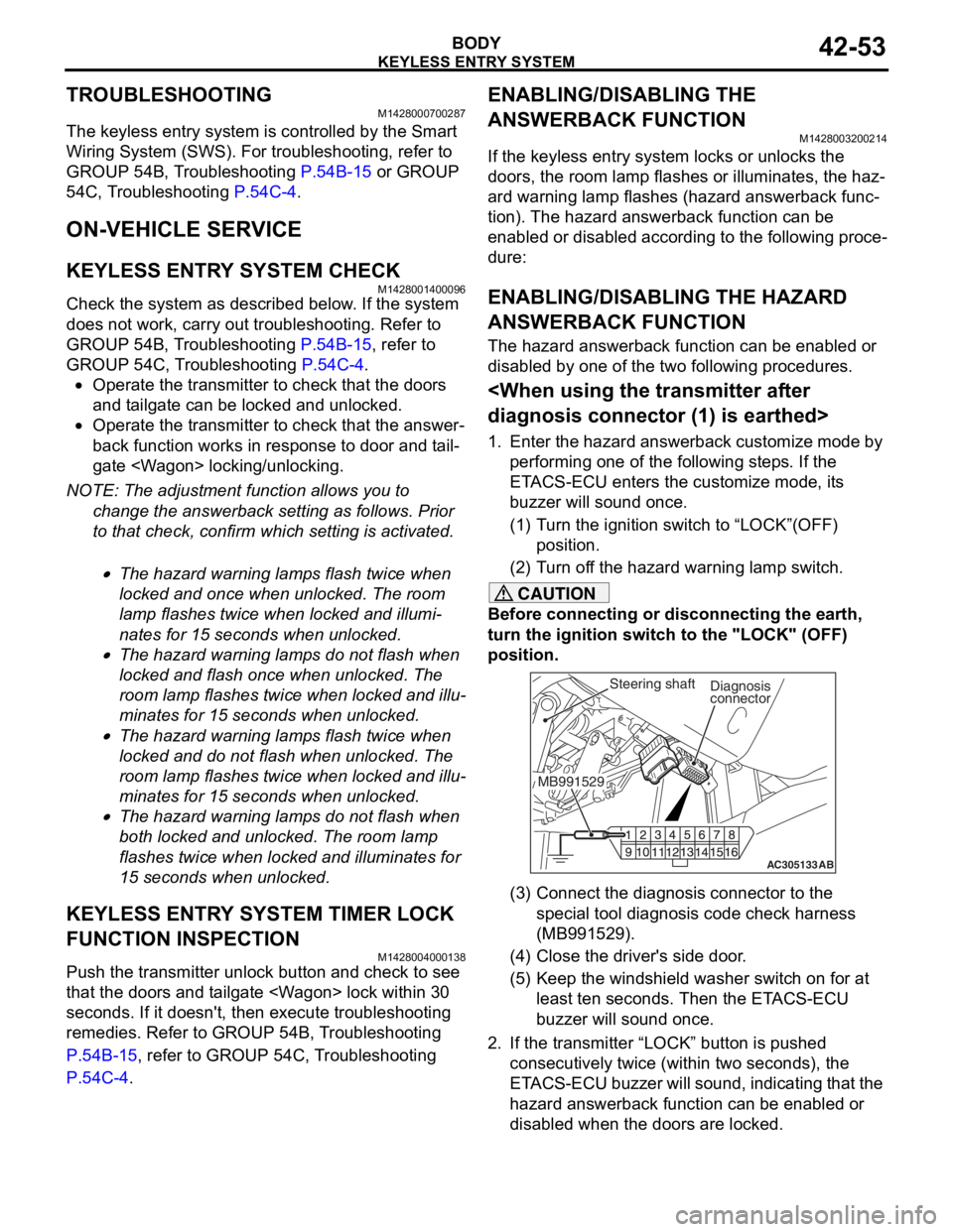
AC305133AB
Diagnosis
connector
MB991529Steering shaft
(3) Connect the diagnosis connector to the special tool diagnosis code check harness
(MB991529).
(4) Close the driver's side door.
(5) Keep the windshield washer switch on for at least ten seconds. Then the ETACS-ECU
buzzer will sound once.
2. If the transmitter “LOCK” button is pushed consecutively twice (wit hin two seconds), the
ETACS-ECU buzzer will sound, indicating that the
hazard answerback function can be enabled or
disabled when the doors are locked.
Page 326 of 800
KEYLESS ENTRY SYSTEM
BODY42-54
•Enable the hazard answerback function
when the doors are locked: The
ETACS-ECU buzzer will sound once.
•Disable the hazard answerback function
when the doors are locked: The
ETACS-ECU buzzer will sound twice.
3. If the transmitter “UNLOCK” button is pushed consecutively twice (wit hin two seconds), the
ETACS-ECU buzzer will sound, indicating that the
hazard answerback function can be enabled or
disabled when the doors are unlocked.
•Enable the hazard answerback function
when the doors are unlocked: The
ETACS-ECU buzzer will sound once.
•Disable the hazard answerback function
when the doors are unlocked: The
ETACS-ECU buzzer will sound twice.
4. Exit the hazard answer back customize mode by
observing one of the following steps.
(1) Disconnect diagnosis connector terminal (1) form the earth.
(2) Turn the ignition switch to position other then “LOCK”(OFF), or remove the ignition key.
(3) Open the driver's side door.
(4) Any other warning buzzer output occurs.
NOTE: If any operation is not done for at least three
minutes after the ETACS-ECU has entered the cus
-
tomize mode, the hazard answerback customize
mode will be canceled automatically.
connector>
1. Enter the hazard answerback customize mode by performing one of the following steps. If the
ETACS-ECU enters the customize mode, its
buzzer will sound once.
(1) Turn the ignition switch to “LOCK”(OFF) position.
(2) Turn off the hazard warning lamp switch.
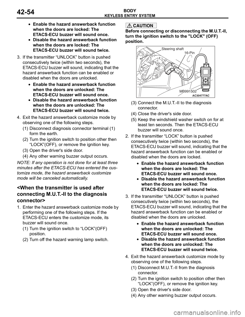
CAUTION
Before connecting or disconnecting the M.U.T.-II,
turn the ignition switch to the "LOCK" (OFF)
position.
AC304777
Steering shaft
ACMB991502
16-Pin
(3) Connect the M.U.T.-II to the diagnosis
connector.
(4) Close the driver's side door.
(5) Keep the windshield washer switch on for at least ten seconds. Then the ETACS-ECU
buzzer will sound once.
2. If the transmitter “LOCK” button is pushed consecutively twice (wit hin two seconds), the
ETACS-ECU buzzer will sound, indicating that the
hazard answerback function can be enabled or
disabled when the doors are locked.
•Enable the hazard answerback function
when the doors are locked: The
ETACS-ECU buzzer will sound once.
•Disable the hazard answerback function
when the doors are locked: The
ETACS-ECU buzzer will sound twice.
3. If the transmitter “UNLOCK” button is pushed consecutively twice (wit hin two seconds), the
ETACS-ECU buzzer will sound, indicating that the
hazard answerback function can be enabled or
disabled when the doors are unlocked.
•Enable the hazard answerback function
when the doors are unlocked: The
ETACS-ECU buzzer will sound once.
•Disable the hazard answerback function
when the doors are unlocked: The
ETACS-ECU buzzer will sound twice.
4. Exit the hazard answer back customize mode by
observing one of the following steps.
(1) Disconnect M.U.T.-II from the diagnosis
connector.
(2) Turn the ignition switch to position other then “LOCK”(OFF), or remove the ignition key.
(3) Open the driver's side door.
(4) Any other warning buzzer output occurs.