height MITSUBISHI LANCER 2006 Workshop Manual
[x] Cancel search | Manufacturer: MITSUBISHI, Model Year: 2006, Model line: LANCER, Model: MITSUBISHI LANCER 2006Pages: 800, PDF Size: 45.03 MB
Page 40 of 800
THERMOSTAT
ENGINE COOLING14-26
>>B<< RADIATOR LOWER HOSE
CONNECTION
AC200642
Mating marks
Projection
Cooling water inlet
hose fitting
AH
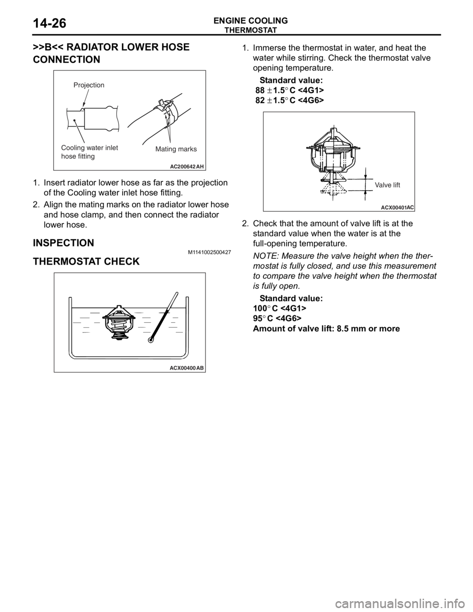
1.In sert ra diato r lower h o se a s fa r as th e projection
of the Cooling wa ter inlet ho se fitting .
2.Align the mating marks on the radiator lower hose
an d hose clamp, and then connect the radia t or
lower hose.
INSPECTION
M1 141 0025 0042 7
THERMOSTA T CHECK
ACX00400
AB
1.Imme rse th e thermost at in water , and h eat the
wate r wh ile stirring. Ch eck the th ermost a t va lve
o penin g temperatu r e.
St andard va lue:
88 ± 1.5°C <4G1 >
82 ± 1.5°C <4G6 >
ACX00401 AC
Valve lift
2.
Check t hat the amo unt of valve lif t is at the
st a ndard valu e when th e water is at the
fu ll-o penin g temperatu r e.
NOTE: Meas ure the valve height when the the r-
mostat is fu lly closed , and use t h is measurement
to
comp are the valve h e ight wh en the thermost at
is fully open.
St andard va lue:
100°C <4G1>
95°C <4G6>
Amou nt of val ve lif t: 8 . 5 mm or more
Page 71 of 800
CHARGING SYSTEM
ENGINE ELECTRICAL16-9
WAVEFORM CHECK USING AN OSCILLOSCOPE
M1161001200124
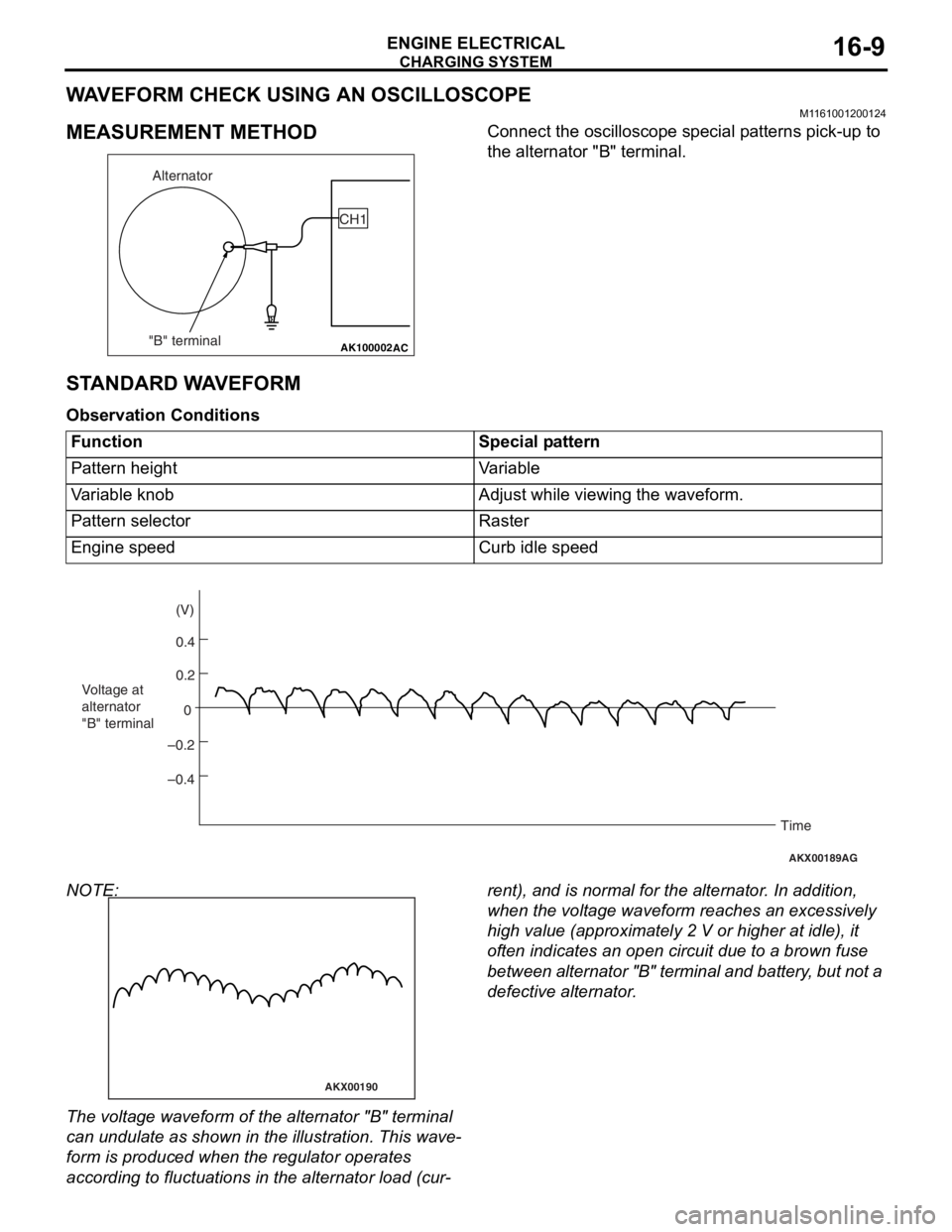
MEASUREMENT METHOD
AK100002
Alternator
"B" terminal CH1
AC
Co
nnect the oscillo scope specia l p a tt erns p i ck-up to
the alternato
r "B" terminal.
STANDARD W A VEFORM
Observ ation Conditi ons
FunctionSpecial pattern
Pattern heightVariable
Variable knobAdjust while viewing the waveform.
Pattern selectorRaster
Engine speedCurb idle speed
AKX00189
0.4 (V)
0.2
0
–0.2
–0.4
Voltage at
alternator
"B" terminal
Time
AG
NOTE:
AKX00190
The volt age waveform of th e alte rnator "B" t e rminal
can u
ndulate as sho w n in th e illustratio n . This wave
-
form is produce d when t he regu lator operate s
accordin
g to fluctu ation s in the alterna t or loa d (cu r
-
rent), and is normal fo r the alterna t or . In ad dition,
wh
en the volt ag e wavef o rm re ache s an excessively
high
value (app roximate ly 2 V or higher at idle ), it
of
ten indicates an o pen circuit du e to a brown fuse
be
twe e n a l te rn at or "B " t e r m in al an d ba tt er y , b u t n o t a
defective alte
rnator .
Page 90 of 800
AK202711
SegmentUndercut
Mica
AB
ST ARTING SYS TEM
ENGINE ELECTRICAL16-28
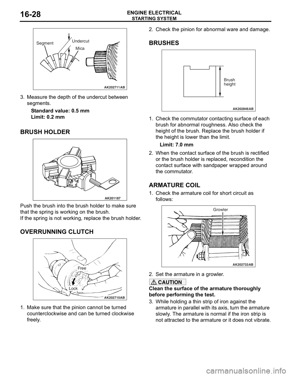
3.Measure the depth of the undercut be twe en
segment s.
St andard va lue: 0.5 mm
Limit: 0.2 mm
BRUSH HOLDER
AK201187
Push th e brush in to the b r ush hold e r to make sure
that the
spring is working o n the b r ush.
If the spring is not working, repla c e th e brush holder .
OVERRUNNING CLUTCH
AK202710
Free
Lock
AB
1.Make sure that th e pin i on canno t be tu rned
counte r clo ckwise a nd ca n be tu rned clockwise
fre e ly .
2.Check t he pinion for abn ormal ware an d damage.
BRUSHES
AK202846
Brush
height
AB
1.Che ck the commut ator con t a c tin g surface of each
b r ush f o r abno rmal rough ness. Also ch eck the
h e ight of the brush . Replace th e brush holder if
th e height is lo we r than t he limit.
Limit: 7.0 mm
2.Wh en the con t act su rface of the brush is rectified
o r the bru s h h o lder is re placed, re cond itio n the
cont act surfa c e wit h san d p a p e r wrapped around
th e co mmu t a t o r .
ARMATURE COIL
1.Check t he armature coil for short circuit a s
fo llows:
AK202733
Growler
AB
2.Set the armature in a growler .
CAUTION
Clean the surface of the armature thoroughly
before performing the test.
3. While holding a thin strip of iron against the
armature in parallel with it s axis, turn the armature
slowly. The armature is normal if the iron strip is
not attracted to the armature or it does not vibrate.
Page 96 of 800
IGNITION SYSTEM
ENGINE ELECTRICAL16-34
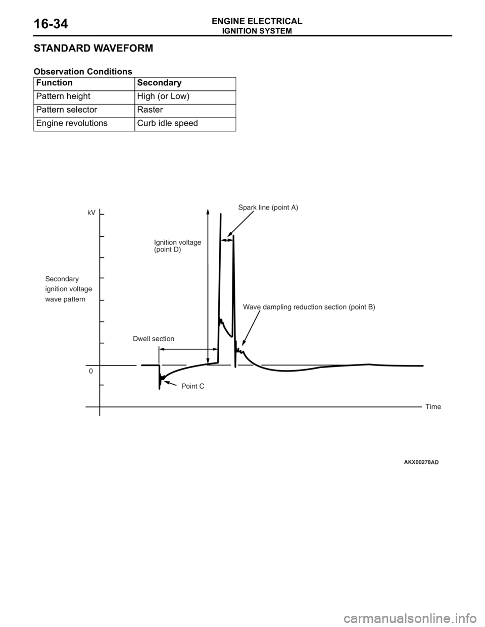
STANDARD WAVEFORM
Observation Conditions
FunctionSecondary
Pattern heightHigh (or Low)
Pattern selectorRaster
Engine revolutionsCurb idle speed
AKX00278
kV0
Secondary
ignition voltage
wave pattern
Ignition voltage
(point D)
Spark line (point A)
Dwell section Wave dampling reduction section (point B)
Point C Time
AD
Page 97 of 800
IGNITION SYSTEM
ENGINE ELECTRICAL16-35
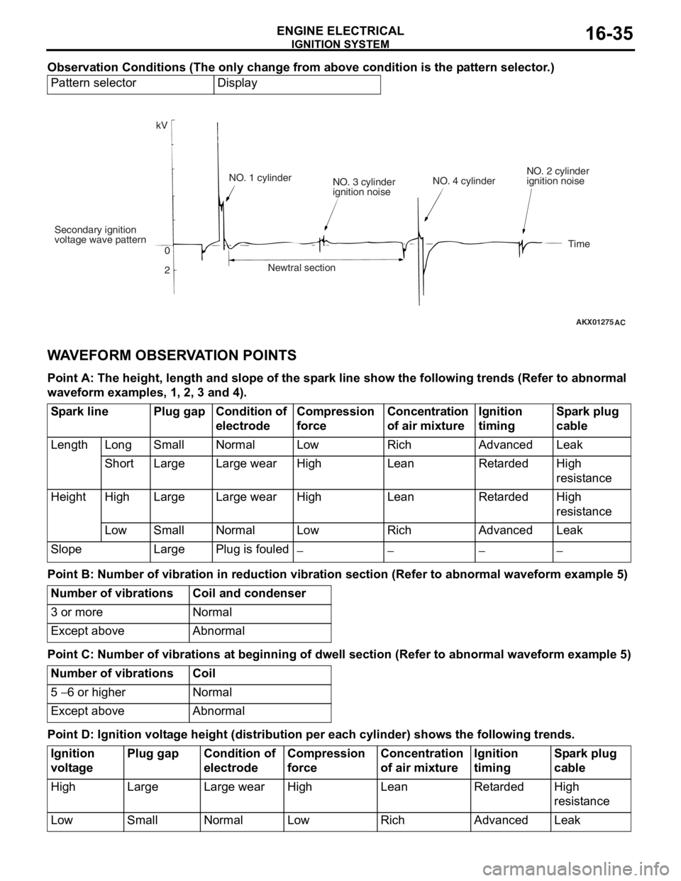
Observation Conditions (The only change from above condition is the pattern selector.)
Pattern selectorDisplay
AKX01275
kV
Secondary ignition
voltage wave pattern 0
2NO. 1 cylinder
NO. 3 cylinder
ignition noise
Newtral section NO. 4 cylinder
NO. 2 cylinder
ignition noise
Time
AC
WA VEFORM OBSER V A T ION POINTS
Point A: The he ight, len g th and s l ope of th e sp a r k line sho w the following trends (Re f er to abnorma l
wave
form exam ples, 1 , 2, 3 a nd 4).
Spark linePlug gapCondition of
electrodeCompression
force Concentration
of air mixtureIgnition
timingSpark plug
cable
LengthLongSmallNormalLowRichAdvancedLeak
ShortLargeLarge wearHigh LeanRetardedHigh
resistance
HeightHighLargeLarge wearHighLeanRetardedHigh
resistance
LowSmallNormalLow RichAdvancedLeak
SlopeLargePlug is fouled−−−−
Point B: Number of v i bra t ion in red uction vi bra t ion sec tion (Refer to a bnormal wavefo r m examp l e 5)
Number of vibrationsCoil and condenser
3 or moreNormal
Except aboveAbnormal
Point C: Number of v i bra t ions a t beginnin g of dwell se ction (Refer to a bnormal wave form exam ple 5)
Number of vibrationsCoil
5 − 6 or higherNormal
Except aboveAbnormal
Point D: Ignition volt a g e height (distribution per each cylinder) s hows the follo wing tren ds.
Ignition
voltagePlug gapCondition of
electrodeCompression
forceConcentration
of air mixtureIgnition
timingSpark plug
cable
HighLargeLarge wearHighLeanRetardedHigh
resistance
LowSmallNormalLowRichAdvancedLeak
Page 273 of 800
42-1
GROUP 42
BODY
CONTENTS
HOOD . . . . . . . . . . . . . . . . . . . . .42-3
ON-VEHICLE SERVICE. . . . . . . . .42-3
ADJUSTMENT OF CLEARANCE
AROUND HOOD . . . . . . . . . . . . . . . . . . 42-3
ADJUSTMENT OF ALIGNMENT OF
HOOD STEPPED PORTION AND
HOOD STRIKER . . . . . . . . . . . . . . . . . . 42-3
ADJUSTMENT OF HOOD HEIGHT . . . 42-3
HOOD . . . . . . . . . . . . . . . . . . . . . . .42-4
REMOVAL AND INSTALLATION . . . . . 42-4
FENDER . . . . . . . . . . . . . . . . . . .42-5
SPECIAL TOOL . . . . . . . . . . . . . . .42-5
FENDER . . . . . . . . . . . . . . . . . . . . .42-6
REMOVAL AND INSTALLATION . . . . . 42-6
FUEL FILLER LID . . . . . . . . . . .42-8
REMOVAL AND INSTALLATION .42-8
STRUT TOWER BAR . . . . . . . .42-9
REMOVAL AND INSTALLATION .42-9
WINDOW GLASS . . . . . . . . . . . 42-10
ADHESIVE . . . . . . . . . . . . . . . . . . .42-10
SPECIAL TOOLS . . . . . . . . . . . . . .42-10
WINDOW REPAIR . . . . . . . . . . . . .42-10
WINDSHIELD . . . . . . . . . . . . . . . . .42-12
REMOVAL AND INSTALLATION . . . . . . 42-12
REAR WINDOW GLASS
REMOVAL AND INSTALLATION . . . . . . 42-17
QUARTER WINDOW GLASS
REMOVAL AND INSTALLATION . . . . . . 42-20
TAILGATE WINDOW GLASS
REMOVAL AND INSTALLATION . . . . . . 42-23
DOOR . . . . . . . . . . . . . . . . . . . . 42-25
SERVICE SPECIFICA TIONS . . . . .42-25
SEALANT . . . . . . . . . . . . . . . . . . . .42-25
SPECIAL TOOLS . . . . . . . . . . . . . .42-26
Continued on next page
Page 274 of 800
42-2
TROUBLESHOOTING . . . . . . . . . .42-26
ON-VEHICLE SERVICE. . . . . . . . .42-27
DOOR FIT ADJUSTMENT. . . . . . . . . . . 42-27
DOOR WINDOW GLASS
ADJUSTMENT . . . . . . . . . . . . . . . . . . . . 42-28
GLASS SLIDING MECHANISM CHECK
AND ADJUSTMENT . . . . . . . . . . . . . . . 42-28
POWER WINDOW OPERATING
CURRENT CHECK . . . . . . . . . . . . . . . . 42-28
POWER WINDOW RELAY CHECK . . . 42-29
CIRCUIT BREAKER (INCORPORATED
IN THE POWER WINDOW MOTOR)
INSPECTION . . . . . . . . . . . . . . . . . . . . . 42-29
POWER WINDOW CHECK . . . . . . . . . . 42-29
CENTRAL DOOR LOCKING SYSTEM
INSPECTION . . . . . . . . . . . . . . . . . . . . . 42-29
DOOR OUTSIDE HANDLE PLAY
CHECK . . . . . . . . . . . . . . . . . . . . . . . . . 42-29
DOOR INSIDE HANDLE PLAY
ADJUSTMENT . . . . . . . . . . . . . . . . . . . . 42-30
DOOR ASSEMBLY . . . . . . . . . . . .42-31
REMOVAL AND INSTALLATION . . . . . 42-31
INSPECTION . . . . . . . . . . . . . . . . . . . . . 42-32
DOOR GLASS AND REGULATOR42-32
REMOVAL AND INSTALLATION . . . . . 42-32
INSPECTION . . . . . . . . . . . . . . . . . . . . . 42-34
DOOR HANDLE AND LATCH . . . .42-36
REMOVAL AND INSTALLATION . . . . . 42-36
INSPECTION . . . . . . . . . . . . . . . . . . . . . 42-37
WINDOW GLASS RUNCHANNEL
AND DOOR OPENING
WEATHERSTRIP . . . . . . . . . . . . . .42-39
REMOVAL AND INSTALLATION . . . . . 42-39
TRUNK LID . . . . . . . . . . . . . . . .42-41
SPECIAL TOOL . . . . . . . . . . . . . . .42-41
ON-VEHICLE SERVICE. . . . . . . . .42-41
TRUNK LID ADJUSTMENT . . . . . . . . . . 42-41
ADJUSTMENT OF CLEARANCE
AROUND TRUNK LID . . . . . . . . . . . . . . 42-42
TRUNK LID STRIKER ADJUSTMENT . 42-42
TRUNK LID HEIGHT ADJUSTMENT . . 42-42
TRUNK LID . . . . . . . . . . . . . . . . . . .42-43
REMOVAL AND INSTALLATION . . . . . . 42-43
INSPECTION . . . . . . . . . . . . . . . . . . . . . 42-45
TAILGATE . . . . . . . . . . . . . . . . 42-46
SERVICE SPECIFICATIONS . . . . .42-46
SEALANTS . . . . . . . . . . . . . . . . . . .42-46
SPECIAL TOOL . . . . . . . . . . . . . . .42-46
TROUBLESHOOTING . . . . . . . . . .42-47
ON-VEHICLE SERVICE . . . . . . . . .42-47
TAILGATE FIT ADJUSTMENT. . . . . . . . 42-47
TAILGATE HANDLE PLAY CHECK . . . . 42-47
TAILGATE . . . . . . . . . . . . . . . . . . .42-48
REMOVAL AND INSTALLATION . . . . . . 42-48
TAILGATE HANDLE AND
LATCH . . . . . . . . . . . . . . . . . . . . . .42-50
REMOVAL AND INSTALLATION . . . . . . 42-50
INSPECTION . . . . . . . . . . . . . . . . . . . . . 42-51
KEYLESS ENTRY SYSTEM . . 42-51
SERVICE SPECIFICATIONS . . . . .42-51
SPECIAL TOOLS . . . . . . . . . . . . . .42-52
TROUBLESHOOTING . . . . . . . . . .42-53
ON-VEHICLE SERVICE . . . . . . . . .42-53
KEYLESS ENTRY SYSTEM CHECK. . . 42-53
KEYLESS ENTRY SYSTEM TIMER
LOCK FUNCTION INSPECTION . . . . . . 42-53
ENABLING/DISABLING THE
ANSWERBACK FUNCTION . . . . . . . . . 42-53
HOW TO REGISTER SECRET CODE . 42-55
TRANSMITTER. . . . . . . . . . . . . . . .42-58
DISASSEMBLY AND REASSEMBLY . . 42-58
INSPECTION . . . . . . . . . . . . . . . . . . . . . 42-59
Page 275 of 800
HOOD
BODY42-3
HOOD
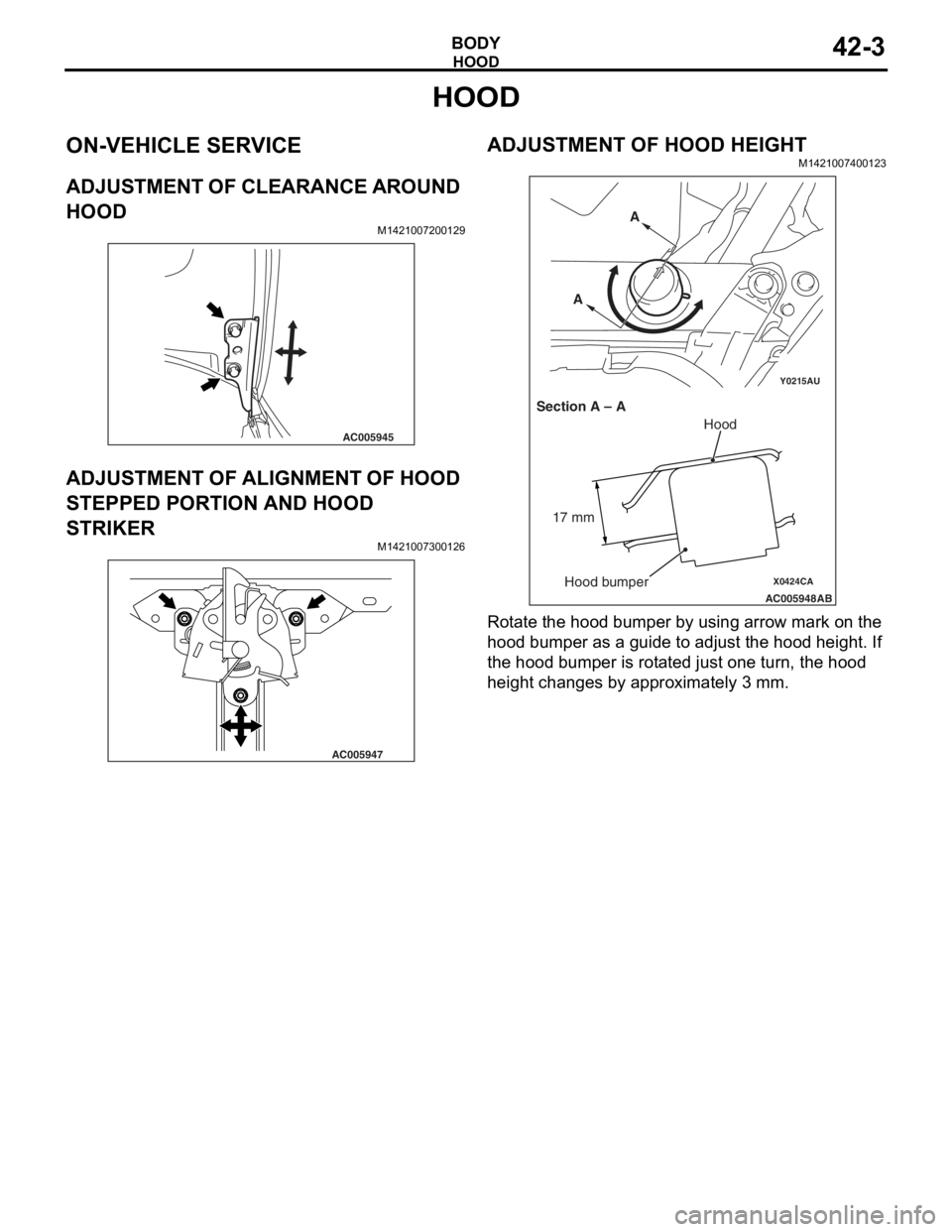
ON-VEHICLE SERVICE
ADJUSTMENT OF CLEARANCE AROUND
HOOD
M1421007200129
AC005945
ADJUSTMENT OF ALIGNMENT OF HOOD
STEPPED PORTION AND HOOD
STRIKER
M14210073 0012 6
AC005947
ADJUSTMENT OF HOOD HEIGHT
M14210074 0012 3
Y0215AU
X0424CA
AC005948
AB
Section A – A A
A
Hood
Hood bumper
17 mm
Ro
t a te t he hood bu mper by using arrow mark o n the
hood bu
mpe r as a g u ide t o adju s t the hood h e ight . If
the hoo
d bumper is rot a te d just one turn, th e hood
heigh
t cha nges by approximately 3 mm.
Page 276 of 800
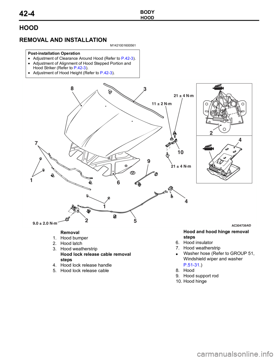
HOOD
BODY42-4
HOOD
REMOVAL AND INSTALLATION
M1421001600561
Post-installation Operation
•Adjustment of Clearance Around Hood (Refer to P.42-3).
•Adjustment of Alignment of Hood Stepped Portion and
Hood Striker (Refer to
P.42-3).
•Adjustment of Hood Height (Refer to P.42-3).
AC304739
1
1
2 2
4 4
5
6
7 3
8
910
AD9.0 ± 2.0 N·m 21 ± 4 N·m
11 ± 2 N·m
21 ± 4 N·m
Removal
1.Hood bumper
2.Hood latch
3.Hood weatherstrip
Hood lock release cable removal
steps
4.Hood lock release handle
5.Hood lock release cable
Hood and hood hinge removal
steps
6.Hood insulator
7.Hood weatherstrip
•Washer hose (Refer to GROUP 51,
Windshield wiper and washer
P.51-31.)
8.Hood
9.Hood support rod
10.Hood hinge
Page 280 of 800
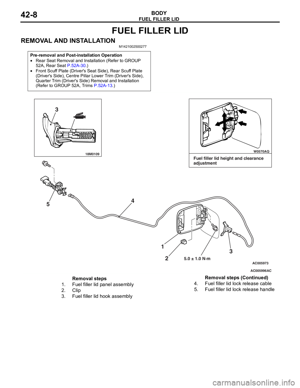
FUEL FILLER LID
BODY42-8
FUEL FILLER LID
REMOVAL AND INSTALLATIONM1421002500277
Pre-removal and Post-installation Operation
•Rear Seat Removal and Installation (Refer to GROUP
52A, Rear Seat
P.52A-30.)
•Front Scuff Plate (Driver's Seat Side), Rear Scuff Plate
(Driver's Side), Centre Pillar Lower Trim (Driver's Side),
Quarter Trim (Driver's Side) Removal and Installation
(Refer to GROUP 52A, Trims
P.52A-13.)
18M0109 W0570AQ
AC005996
AC005973
3
5 4
3
2
1
5.0 ± 1.0 N·m
AC
Fuel filler lid height and clearance
adjustment
Removal steps
1.Fuel filler lid panel assembly
2.Clip
3.Fuel filler lid hook assembly
4.Fuel filler lid lock release cable
5.Fuel filler lid lock release handle
Removal steps (Continued)