ignition coil MITSUBISHI LANCER 2006 Workshop Manual
[x] Cancel search | Manufacturer: MITSUBISHI, Model Year: 2006, Model line: LANCER, Model: MITSUBISHI LANCER 2006Pages: 800, PDF Size: 45.03 MB
Page 63 of 800
16-1
GROUP 16
ENGINE
ELECTRICAL
CONTENTS
CHARGING SYSTEM . . . . . . . .16-2
GENERAL INFORMATION . . . . . .16-2
SERVICE SPECIFICATIONS. . . . .16-3
SPECIAL TOOL . . . . . . . . . . . . . . .16-3
ON-VEHICLE SERVICE. . . . . . . . .16-3
ALTERNATOR OUTPUT LINE VOLTAGE
DROP TEST . . . . . . . . . . . . . . . . . . . . . 16-3
OUTPUT CURRENT TEST . . . . . . . . . . 16-5
REGULATED VOLTAGE TEST . . . . . . . 16-7
WAVEFORM CHECK USING AN
OSCILLOSCOPE . . . . . . . . . . . . . . . . . . 16-9
ALTERNATOR ASSEMB LY . . . . .16-12
REMOVAL AND INSTALLATION
<4G1> . . . . . . . . . . . . . . . . . . . . . . . . . . 16-12
REMOVAL AND INSTALLATION
<4G6> . . . . . . . . . . . . . . . . . . . . . . . . . . 16-13
DISASSEMBLY AND REASSEMBLY . . 16-15
INSPECTION . . . . . . . . . . . . . . . . . . . . . 16-17
STARTING SYSTEM . . . . . . . . .16-19
GENERAL INFORMATION . . . . . .16-19
SERVICE SPECIFICATIONS. . . . .16-20
STARTER MOTOR ASSEMBLY . .16-21
REMOVAL AND INSTALLATION
<4G1> . . . . . . . . . . . . . . . . . . . . . . . . . . 16-21
REMOVAL AND INSTALLATION
<4G6> . . . . . . . . . . . . . . . . . . . . . . . . . . 16-22
STARTER MOTOR ASSEMBLY
INSPECTION . . . . . . . . . . . . . . . . . . . . . 16-23
DISASSEMBLY AND REASSEMBLY . . 16-26
INSPECTION . . . . . . . . . . . . . . . . . . . . . 16-27
IGNITION SYSTEM . . . . . . . . . 16-30
GENERAL INFORMATION . . . . . .16-30
SERVICE SPECIFICATIONS . . . . .16-31
SPECIAL TOOL . . . . . . . . . . . . . . .16-31
ON-VEHICLE SERVICE . . . . . . . . .16-32
IGNITION COIL (WITH BUILT-IN
POWER TRANSISTOR) CHECK . . . . . . 16-32
RESISTIVE CORD CHECK . . . . . . . . . . 16-32
SPARK PLUG CHECK AND CLEANING
<4G1>. . . . . . . . . . . . . . . . . . . . . . . . . . . 16-32
SPARK PLUG CHECK AND CLEANING
<4G6>. . . . . . . . . . . . . . . . . . . . . . . . . . . 16-33
CAMSHAFT POSITION SENSOR
CHECK . . . . . . . . . . . . . . . . . . . . . . . . . . 16-33
CRANK ANGLE SENSOR CHECK . . . . 16-33
DETONATION SENSOR CHECK . . . . . 16-33
IGNITION SECONDARY VOLTAGE
WAVEFORM CHECK USING AN
OSCILLOSCOPE . . . . . . . . . . . . . . . . . . 16-33
IGNITION COIL RELAY CHECK . . . . . . 16-37
IGNITION COIL . . . . . . . . . . . . . . . .16-38
REMOVAL AND INSTALLATION
<4G1>. . . . . . . . . . . . . . . . . . . . . . . . . . . 16-38
REMOVAL AND INSTALLATION
<4G6>. . . . . . . . . . . . . . . . . . . . . . . . . . . 16-39
CAMSHAFT POSITION SENSOR .16-40
REMOVAL AND INSTALLATION . . . . . . 16-40
CRANKSHAFT POSITION SENSOR16-41
REMOVAL AND INSTALLATION
<4G1>. . . . . . . . . . . . . . . . . . . . . . . . . . . 16-41
REMOVAL AND INSTALLATION
<4G6>. . . . . . . . . . . . . . . . . . . . . . . . . . . 16-42
DETONATION SENSOR . . . . . . . .16-43
REMOVAL AND INSTALLATION . . . . . . 16-43
Page 64 of 800
CHARGING SYSTEM
ENGINE ELECTRICAL16-2
CHARGING SYSTEM
GENERAL INFORMATIONM1161000100522
The charging system uses the alternator output to
keep the battery charged at a constant level under
various electrical loads.
OPERATION
AKX00183
VoltageTime
Approximately
14.4 V
AC
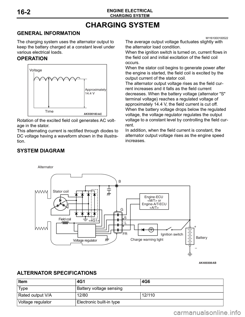
Rota tion of the excited fi eld coil gene rates AC volt-
age in the sta t or .
This alternatin g cur r ent is rectified throu gh diodes to
DC volt
age h a ving a waveform sh own in t he illustra
-
tion.
The average outpu t volt a ge flu c tua t es slightly with
the alternato
r load con d ition.
When the ign i tion switch is t u rned on, current flows in
the field coil and initial e
x cit a tion of the field coil
occurs.
When the st ator coil beg ins to gen erate p o wer af ter
the eng
ine is st a r ted, th e fie l d coil is excited by th e
output
curren t of th e st ator coil.
The alternator outpu t volt a ge rises as th e fie l d cur-
rent increa ses and it falls a s the field cu rrent
decre
ases. Whe n the b a ttery volt a ge (alternato r "S"
terminal volt
ag e) reaches a regulated volt ag e of
approximately 14.4
V , the field current is cut o f f.
When th
e batte ry volt age drop s be low the regulated
volt
ag e, the volt ag e regulator re gulat es th e outp u t
volt
ag e to a const ant level by contro lling the field cur
-
rent.
In addition, when th e fie l d current is const a n t, the
altern
ator ou tput volt age rise s as the e ngine spe ed
increase
s .
SYSTEM DIAGRAM
AK400308
Alternator
B
Stator coil
Engine-ECU
Engine-A/T-ECU
G
SL
FR
<4G1>
Voltage regulator Charge warning lightIgnition switch
Battery
Field coil
+
–
AB
AL TERNA T O R SPECIFICA T IONS
Item4G14G6
Ty p eBattery voltage sensing
Rated output V/A12/8012/110
Voltage regulatorElectronic built-in type
Page 81 of 800
STARTING SYSTEM
ENGINE ELECTRICAL16-19
STARTING SYSTEM
GENERAL INFORMATIONM1162000100202
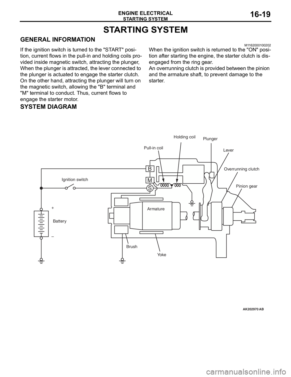
If the ignition switch is turned to the "START" posi-
tion, current flows in the pull-in and holding coils pro-
vided inside magnetic switch, attracting the plunger,
When the plunger is attracted, the lever connected to
the plunger is actuated to engage the starter clutch.
On the other hand, attracting the plunger will turn on
the magnetic switch, allowing the "B" terminal and
"M" terminal to conduct. Thus, current flows to
engage the starter motor.
When the ignition switch is returned to the "ON" posi-
tion after starting the engine, the starter clutch is dis-
engaged from the ring gear.
An overrunning clutch is provided between the pinion
and the armature shaft, to prevent damage to the
starter.
SYSTEM DIAGRAM
AK202970
Pull-in coilHolding coil
Plunger
Lever
Pinion gear
Overrunning clutch
Yo k e
Brush Armature
Ignition switch
Battery
+
–
AB
B
M S
Page 92 of 800
IGNITION SYSTEM
ENGINE ELECTRICAL16-30
IGNITION SYSTEM
GENERAL INFORMATIONM1163000100294
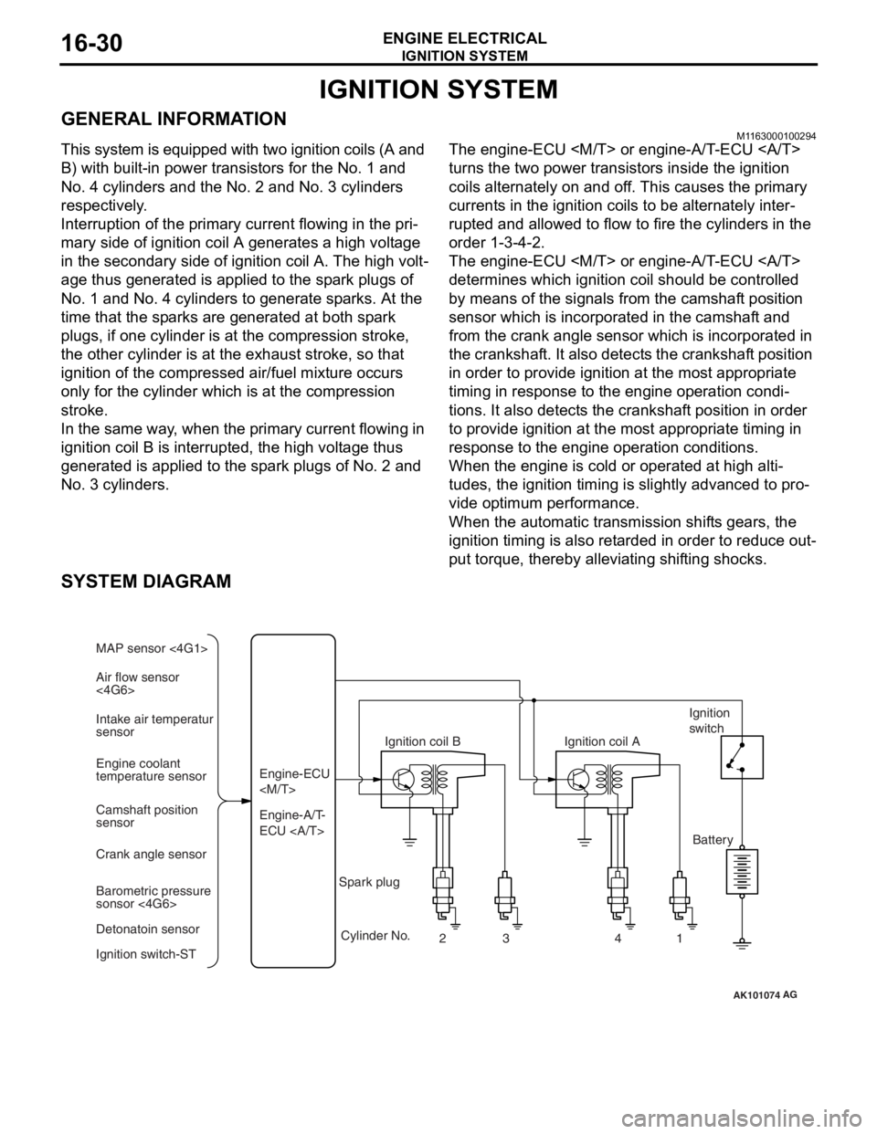
This system is equipped with two ignition coils (A and
B) with built-in power transistors for the No. 1 and
No. 4 cylinders and the No. 2 and No. 3 cylinders
respectively.
Interruption of the primary current flowing in the pri-
mary side of ignition coil A generates a high voltage
in the secondary side of ignition coil A. The high volt
-
age thus generated is applied to the spark plugs of
No. 1 and No. 4 cylinders to generate sparks. At the
time that the sparks are generated at both spark
plugs, if one cylinder is at the compression stroke,
the other cylinder is at the exhaust stroke, so that
ignition of the compressed air/fuel mixture occurs
only for the cylinder which is at the compression
stroke.
In the same way, when the primary current flowing in
ignition coil B is interrupted, the high voltage thus
generated is applied to the spark plugs of No. 2 and
No. 3 cylinders.
The engine-ECU
turns the two power transistors inside the ignition
coils alternately on and off. This causes the primary
currents in the ignition coils to be alternately inter
-
rupted and allowed to flow to fire the cylinders in the
order 1-3-4-2.
The engine-ECU
determines which ignition coil should be controlled
by means of the signals from the camshaft position
sensor which is incorporated in the camshaft and
from the crank angle sensor which is incorporated in
the crankshaft. It also detects the crankshaft position
in order to provide ignition at the most appropriate
timing in response to the engine operation condi
-
tions. It also detects the crankshaft position in order
to provide ignition at the most appropriate timing in
response to the engine operation conditions.
When the engine is cold or operated at high alti-
tudes, the ignition timing is slightly advanced to pro-
vide optimum performance.
When the automatic transmission shifts gears, the
ignition timing is also retarded in order to reduce out
-
put torque, thereby alleviating shifting shocks.
SYSTEM DIAGRAM
AK101074
Air flow sensor
<4G6> MAP sensor <4G1>
Intake air temperatur
sensor
Engine coolant
temperature sensor
Camshaft position
sensor
Crank angle sensor
Barometric pressure
sonsor <4G6>
Detonatoin sensor
Ignition switch-ST Engine-A/T-
ECU Engine-ECU
Ignition coil B
Cylinder No. 23 4
AG
1
Spark plug Ignition coil A
Ignition
switch
Battery
Page 93 of 800
IGNITION SYSTEM
ENGINE ELECTRICAL16-31
IGNITION COIL SPECIFICATION
ItemSpecification
Ty p eMolded 2-coil
SPARK PLUG SPECIFICATIONS
Items4G14G66
NGKBKR6E-11IGR6A11
DENSOK20PR-U11−
CHAMPIONRC8YC4−
SERVICE SPECIFICATIONSM1163000300180
IGNITION COIL
ItemStandard value
Secondary coil resistance kΩ8.5 − 11.5
SPARK PLUG
ItemsStandard valueLimit
Spark plug gap mm4G11.0 − 1.1−
4G61.0 − 1.11.3
RESISTIVE CORD
ItemStandard valueLimit
Resistance kΩ−Maximum 19
SPECIAL TOOL
M1163000600288
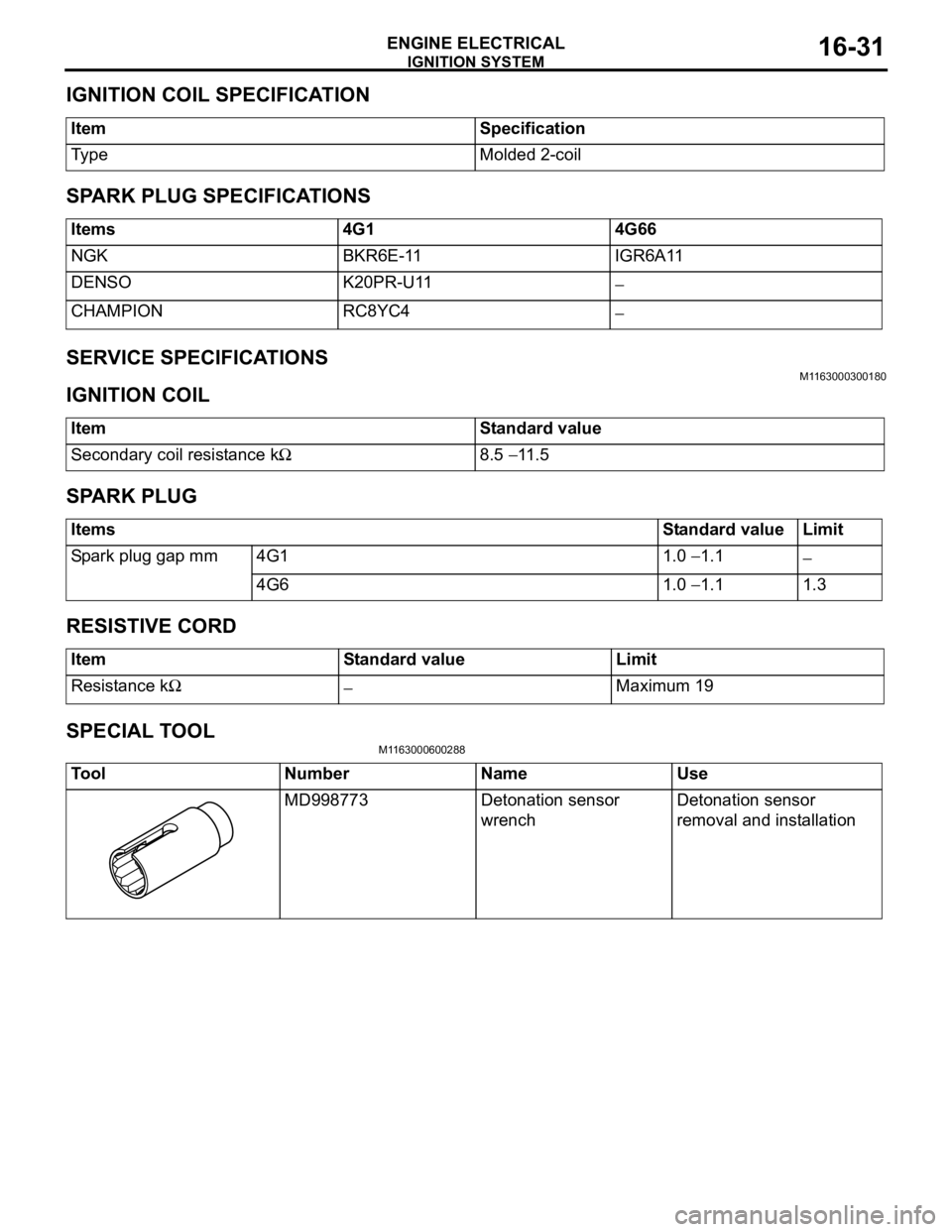
ToolNumberNameUse
MD998773Detonation sensor
wrenchDetonation sensor
removal and installation
Page 94 of 800
IGNITION SYSTEM
ENGINE ELECTRICAL16-32
ON-VEHICLE SERVICE
IGNITION COIL (WITH BUILT-IN POWER
TRANSISTOR) CHECK
M1163001200324
Check by the following procedure, and replace if
there is a malfunction.
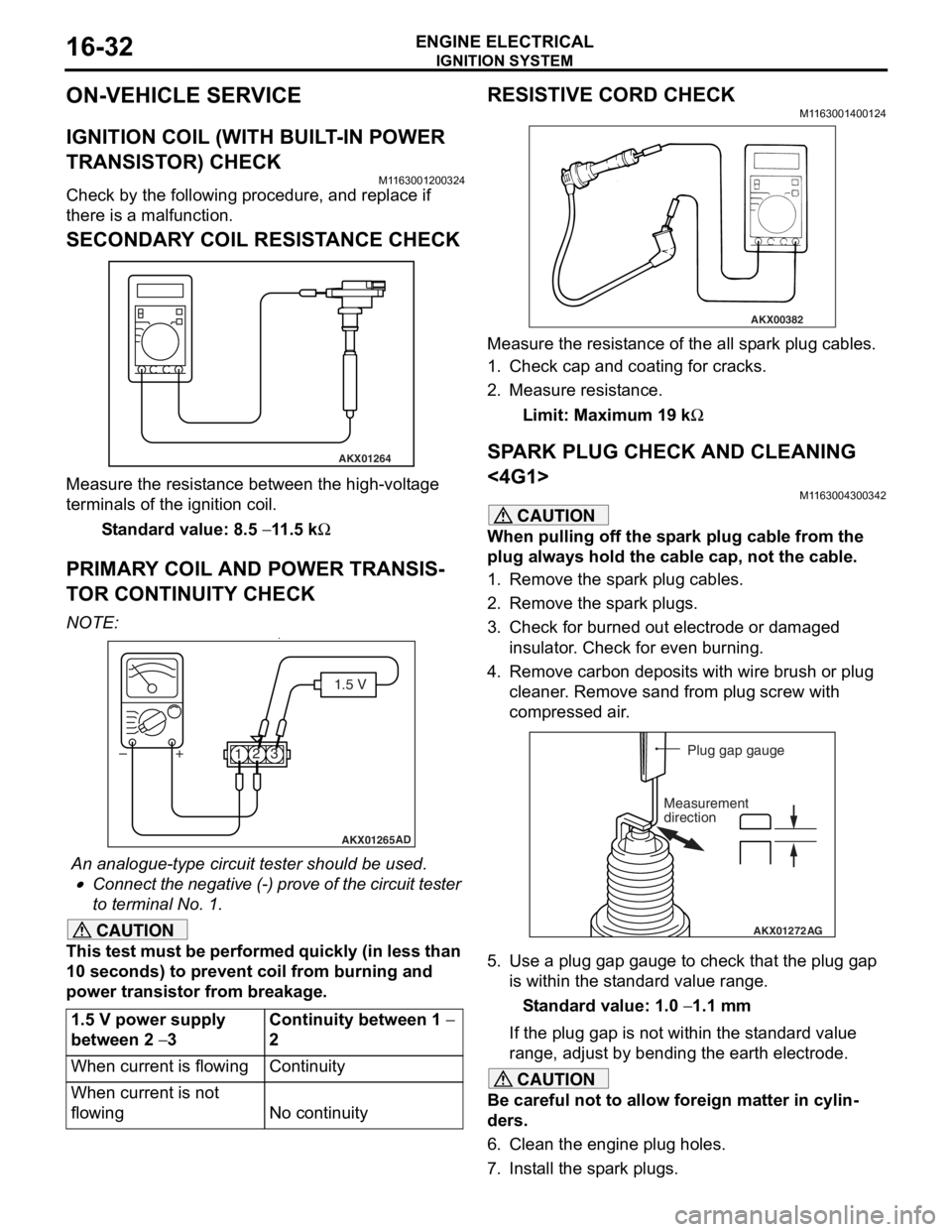
SECONDARY COIL RESISTANCE CHECK
AKX01264
Measure the resist ance bet we en the high- volt ag e
terminals of th
e ign i tio n coil.
St andard va lue: 8.5 − 11 .5 kΩ
PRIM AR Y COIL AND POWER TRANSIS-
TO R CONTINUITY CHECK
NO TE: .•
AKX01265 AD
1.5 V
1 23
+
–
An analogue-t y pe circuit t e ster shou ld be use d .
•Connect the n egative (-) pro v e of the circuit t e ster
to t
e rminal No. 1.
CAUTION
This test must be performed quickly (in less than
10 seconds) to prevent coil from burning and
power transistor from breakage.
1.5 V power supply
between 2
− 3
Continuity between 1 −
2
When current is flowingContinuity
When current is not
flowing
No continuity
RESISTIVE CORD CHECK
M1163001400124
AKX00382
Measure the resistance of the all spark plug cables.
1. Check cap and coating for cracks.
2. Measure resistance.
Limit: Maximum 19 kΩ
SPARK PLUG CHECK AND CLEANING
<4G1>
M1163004300342
CAUTION
When pulling off the spark plug cable from the
plug always hold the cable cap, not the cable.
1. Remove the spark plug cables.
2. Remove the spark plugs.
3. Check for burned out electrode or damaged insulator. Check for even burning.
4. Remove carbon deposits with wire brush or plug cleaner. Remove sand from plug screw with
compressed air.
AKX01272 AG
Plug gap gauge
Measurement
direction
5. Use a plug gap gauge to check that the plug gap is within the standard value range.
Standard value: 1.0 − 1.1 mm
If the plug gap is not within the standard value
range, adjust by bending the earth electrode.
CAUTION
Be careful not to allow foreign matter in cylin-
ders.
6. Clean the engine plug holes.
7. Install the spark plugs.
Page 97 of 800
IGNITION SYSTEM
ENGINE ELECTRICAL16-35
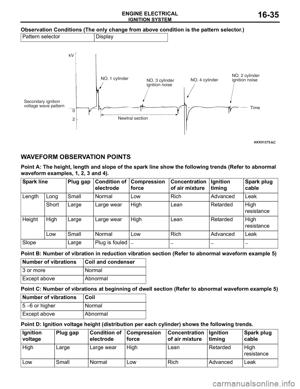
Observation Conditions (The only change from above condition is the pattern selector.)
Pattern selectorDisplay
AKX01275
kV
Secondary ignition
voltage wave pattern 0
2NO. 1 cylinder
NO. 3 cylinder
ignition noise
Newtral section NO. 4 cylinder
NO. 2 cylinder
ignition noise
Time
AC
WA VEFORM OBSER V A T ION POINTS
Point A: The he ight, len g th and s l ope of th e sp a r k line sho w the following trends (Re f er to abnorma l
wave
form exam ples, 1 , 2, 3 a nd 4).
Spark linePlug gapCondition of
electrodeCompression
force Concentration
of air mixtureIgnition
timingSpark plug
cable
LengthLongSmallNormalLowRichAdvancedLeak
ShortLargeLarge wearHigh LeanRetardedHigh
resistance
HeightHighLargeLarge wearHighLeanRetardedHigh
resistance
LowSmallNormalLow RichAdvancedLeak
SlopeLargePlug is fouled−−−−
Point B: Number of v i bra t ion in red uction vi bra t ion sec tion (Refer to a bnormal wavefo r m examp l e 5)
Number of vibrationsCoil and condenser
3 or moreNormal
Except aboveAbnormal
Point C: Number of v i bra t ions a t beginnin g of dwell se ction (Refer to a bnormal wave form exam ple 5)
Number of vibrationsCoil
5 − 6 or higherNormal
Except aboveAbnormal
Point D: Ignition volt a g e height (distribution per each cylinder) s hows the follo wing tren ds.
Ignition
voltagePlug gapCondition of
electrodeCompression
forceConcentration
of air mixtureIgnition
timingSpark plug
cable
HighLargeLarge wearHighLeanRetardedHigh
resistance
LowSmallNormalLowRichAdvancedLeak
Page 98 of 800
IGNITION SYSTEM
ENGINE ELECTRICAL16-36
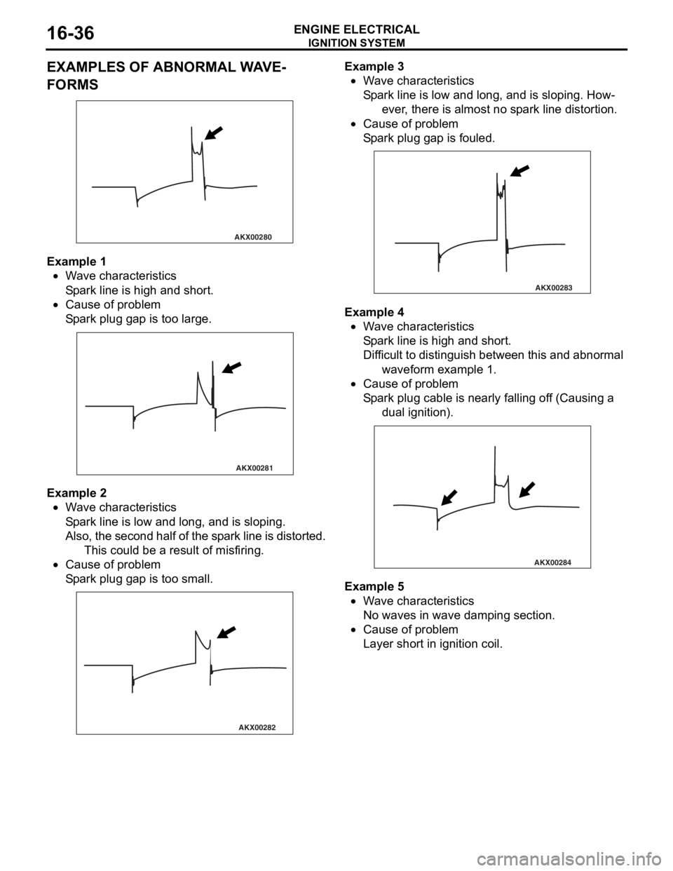
EXAMPLES OF ABNORMAL WAVE-
FORMS
AKX00280
Example 1
•Wa ve ch aracte rist ics
Sp a r k line is high an d sh ort.
•Cause of pr oblem
Sp a r k plug ga p is too large.
AKX00281
Example 2
•Wa ve ch aracte rist ics
Sp a r k line is low and long, a nd is sloping.
Also, the secon d half of the sp ark line is distorted.
This cou l d be a result o f misfiring.
•Cause of pr oblem
Sp a r k plug ga p is too small.
AKX00282
Example 3
•Wa ve ch aracte rist ics
Sp a r k line is low and long, a nd is sloping. How-
ever, there is a l mo st no sp ark lin e distortion.
•Cause of pr oblem
Sp a r k plug ga p is fouled.
AKX00283
Example 4
•Wa ve ch aracte rist ics
Sp a r k line is high an d sh ort.
Diff icu l t to distingu ish be twe en this an d a bnormal
wa vefor m examp l e 1.
•Cause of pr oblem
Sp a r k plug cable is nearly fallin g of f (Ca u sing a
dual ignition ).
AKX00284
Example 5
•Wa ve ch aracte rist ics
No waves in wave damp i ng section.
•Cause of pr oblem
Layer short in ign i tio n coil.
Page 99 of 800
IGNITION SYSTEM
ENGINE ELECTRICAL16-37
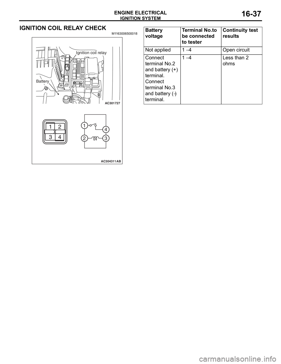
IGNITION COIL RELAY CHECK
M1163006500018
AC301727
2 1
3
4
AC304311AB
Battery
Ignition coil relay
Battery
voltageTerminal No.to
be connected
to testerContinuity test
results
Not applied1 − 4Open circuit
Connect
terminal No.2
and battery (+)
terminal.
Connect
terminal No.3
and battery (
−)
terminal.
1 − 4Less than 2
ohms
Page 100 of 800
IGNITION SYSTEM
ENGINE ELECTRICAL16-38
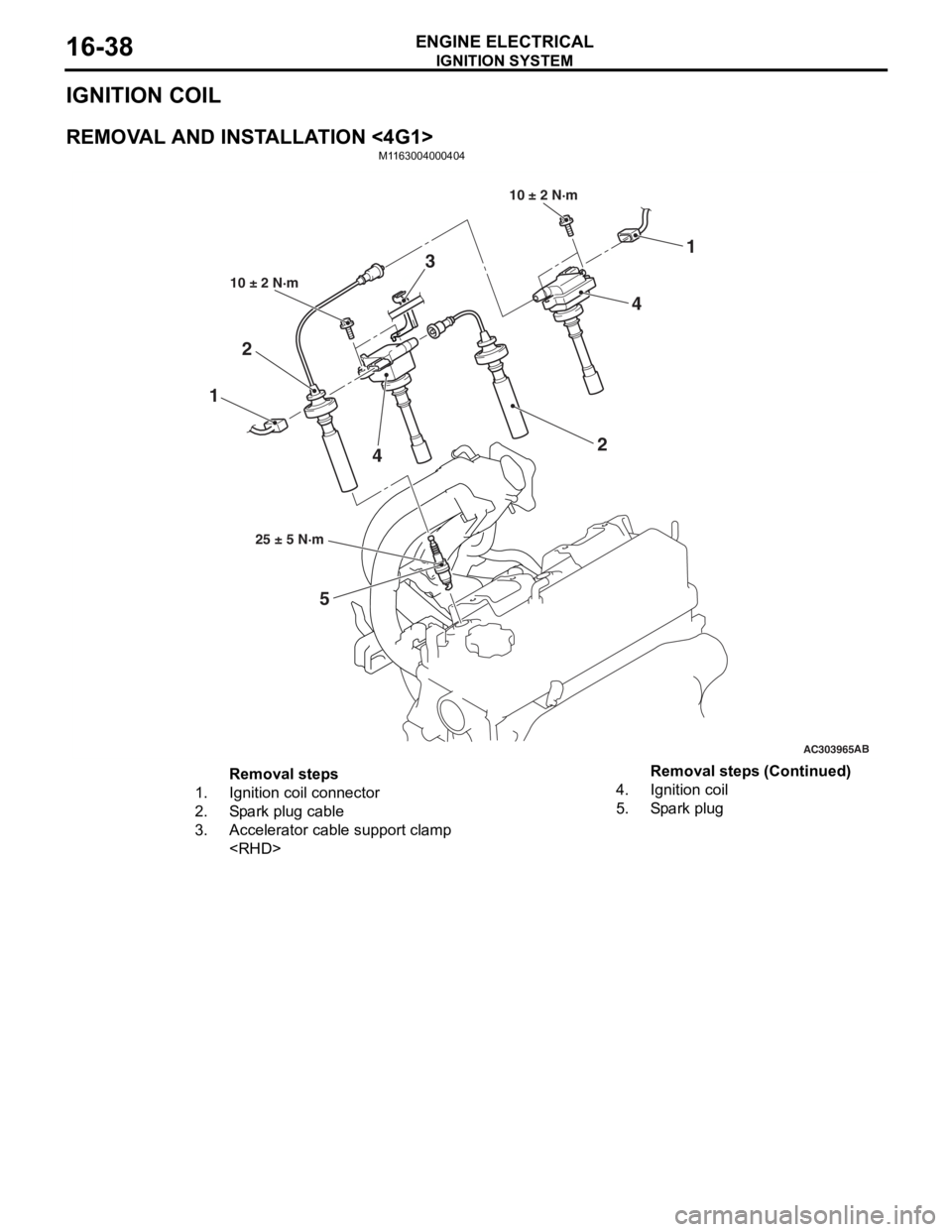
IGNITION COIL
REMOVAL AND INSTALLATION <4G1>
M1163004000404
AC303965AB
11
5
2
2
10 ± 2 N·m
10 ± 2 N·m
25 ± 5 N·m
3
4
4
Removal steps
1.Ignition coil connector
2.Spark plug cable
3.Accelerator cable support clamp
4.Ignition coil
5.Spark plug
Removal steps (Continued)