p.51-9 MITSUBISHI LANCER 2006 Workshop Manual
[x] Cancel search | Manufacturer: MITSUBISHI, Model Year: 2006, Model line: LANCER, Model: MITSUBISHI LANCER 2006Pages: 800, PDF Size: 45.03 MB
Page 285 of 800

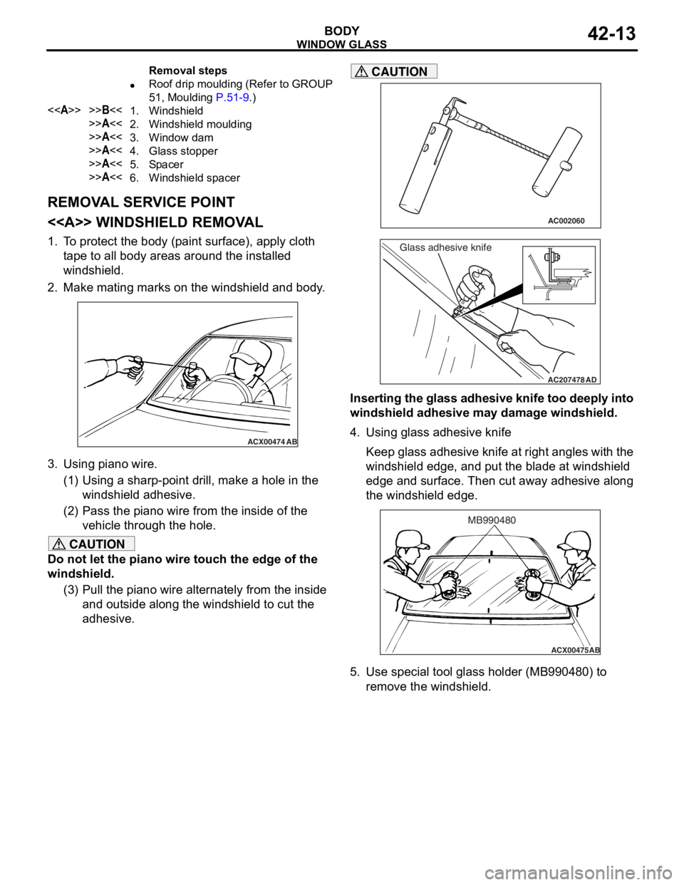
Removal steps
•Roof drip moulding (Refer to GROUP
51, Moulding
P.51-9.)
<>>>B<<1.Windshield
>>A<<2.Windshield moulding
>>A<<3.Window dam
>>A<<4.Glass stopper
>>A<<5.Spa cer
>>A<<6.Windshield spacer
WI NDOW GLASS
BO D Y42-13
REMOV A L SER V ICE POINT
<> WI NDSHIELD REMOV A L
1.T o prot ect th e body (p ain t surfa c e), a pply cloth
t ape to all bod y area s aro und th e inst a lle d
windshield.
2.Make mating marks on th e windshie l d an d body .
ACX00474
AB
3.Using p i ano wire.
(1)U sin g a sharp-po int d r ill, make a h o le in the
windshield ad hesive.
(2)P ass the p i ano wire from the inside of the
veh i cle thro ugh the hole.
CAUTION
Do not let the piano wire touch the edge of the
windshield.
(3) Pull the piano wire alternately from the inside and outside along the windshield to cut the
adhesive.
AC002060
AC207478
Glass adhesive knife
AD
CAUTION
Inserting the glass adhesive knife too deeply into
windshield adhesive may damage windshield.
4. Using glass adhesive knife
Keep glass adhesive knife at right angles with the
windshield edge, and put the blade at windshield
edge and surface. Then cut away adhesive along
the windshield edge.
ACX00475 AB
MB990480
5. Use special tool glass holder (MB990480) to
remove the windshield.
Page 288 of 800

ACX00480
10 mm15 mm
AB
WI ND OW GLAS S
BODY42-16
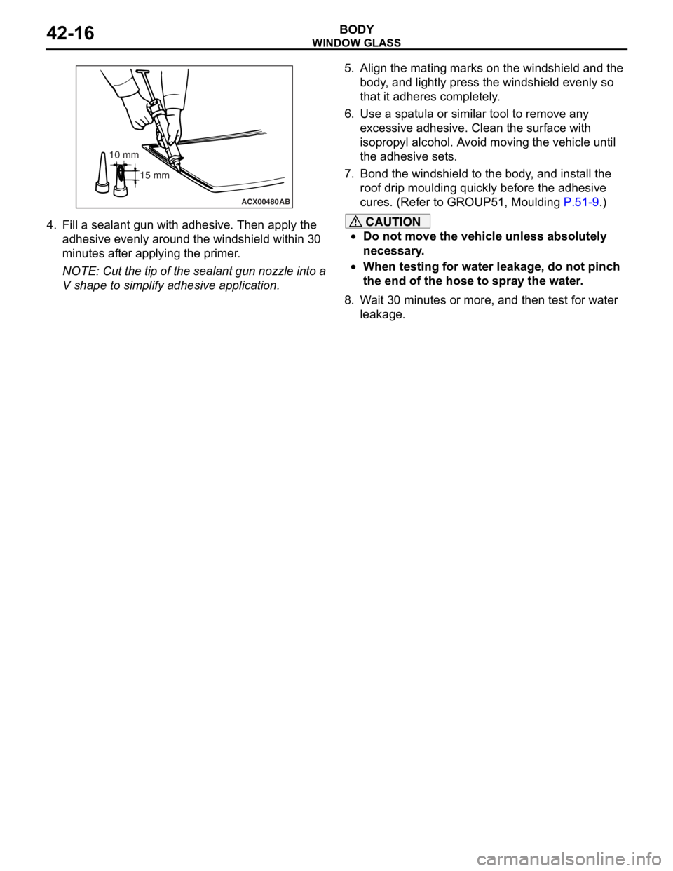
4.Fill a sea l ant gun with adhe sive. The n apply th e
ad hesive even ly a r ound the wind shield within 3 0
minut es af ter applying the pr ime r .
NOTE: Cut the tip of t he seala n t gu n nozzle into a
V shape to simplify adhesive app licatio n.
5.Align t he mating ma rks on th e windshie l d a nd the
b ody , and lig htly press the windshield evenly so
th at it adheres co mpletely .
6.Use a sp a t ula o r similar tool to re move any
e xce ssive adhesive. Clean the surface with
isopr opyl alcohol. A v o i d moving the veh i cle unt il
th e adhe sive set s .
7.Bon d the windsh i eld to the body , a nd in st all the
ro of drip mou l din g quickly b e fore t he adh esive
cures. (Refer to GROUP51, Mou l din g
P.51-9.)
CAUTION
•Do not move the vehicle unless absolutely
necessary.
•When testing for water leakage, do not pinch
the end of the hose to spray the water.
8. Wait 30 minutes or more, and then test for water leakage.
Page 289 of 800

WINDOW GLASS
BODY42-17
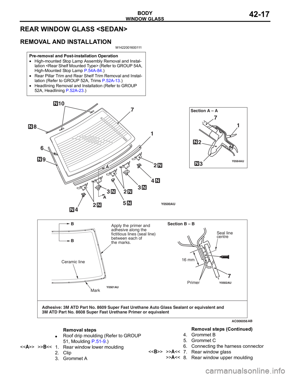
REAR WINDOW GLASS
REMOVAL AND INSTALLATION
M1422001600111
Pre-removal and Post-installation Operation
•High-mounted Stop Lamp Assembly Removal and Instal-lation
High-Mounted Stop Lamp
P.54A-84.)
•Rear Pillar Trim and Rear Shelf Trim Removal and Instal-
lation (Refer to GROUP 52A, Trims P.52A-13.)
•Headlining Removal and Installation (Refer to GROUP
52A, Headlining
P.52A-23.)
Y0500AU
Y0502AUY0501AU
Y0564AU
AC006056
1 1
7
7
AB
6
25
4
9
7
3
N
2N
2N
N
4N
N
3N3N
NN
2N
Ceramic line
Mark
Apply the primer and
adhesive along the
fictitious lines (seal line)
between each of
the marks. Section A – A
Section B – B
Seal line
centre
Primer
8N
10N
Adhesive: 3M ATD Part No. 8609 Super Fast Urethane Auto Glass Sealant or equivalent and
3M ATD Part No. 8608 Super Fast Urethane Primer or equivalent
16 mm
A
A
B
B
Removal steps
•Roof drip moulding (Refer to GROUP
51, Moulding
P.51-9.)
<>>>B<<1.Rear window lower moulding
2.Clip
3.Grommet A
4.Grommet B
5.Grommet C
6.Connecting the harness connector
<>>>A<<7.Rear window glass
>>A<<8.Rear window upper moulding
Removal steps (Continued)