position light MITSUBISHI LANCER 2006 Workshop Manual
[x] Cancel search | Manufacturer: MITSUBISHI, Model Year: 2006, Model line: LANCER, Model: MITSUBISHI LANCER 2006Pages: 800, PDF Size: 45.03 MB
Page 66 of 800

CHARGING SYSTEM
ENGINE ELECTRICAL16-4
2. Turn the ignition switch to the "LOCK" (OFF)
position.
3. Disconnect the negative battery cable.
4. Connect a clamp-type DC test ammeter with a
range of 0
‚ąí 120 A to the alternator "B" terminal
output wire.
NOTE: The way of disconnecting the alternator
output wire and of connecting the ammeter is pos
-
sibly not found the problem that the output current
is dropping due to the insufficient connection
between terminal "B" and the output wire.
5. Connect a digital-type voltmeter between the
alternator "B" terminal and the battery (+)
terminal. [Connect the (+) lead of the voltmeter to
the "B" terminal and the connect the (-) lead of the
voltmeter to the battery (+) cable].
6. Reconnect the negative battery cable.
7. Connect a tachometer or the M.U.T.-II/III (Refer to
GROUP 11A
‚ąí On-vehicle Service ‚ąí Idle speed
check <4G1>
P.11A-11 or GROUP 11C ‚ąí
On-vehicle Service ‚ąí Idle speed check <4G6>
P.11C-11).
8. Leave the hood open.
9. Start the engine.
10.With the engine running at 2,500 r/min, turn the
headlamps and other lamps on and off to adjust
the alternator load so that the value displayed on
the ammeter is slightly above 30 A.
Adjust the engine speed by gradually decreasing
it until the value displayed on the ammeter is 30
A. Take a reading of the value displayed on the
voltmeter at this time.
Limit: maximum 0.3 V
NOTE: When the alternator output is high and the
value displayed on the ammeter does not
decrease until 30 A, set the value to 40 A. Read
the value displayed on the voltmeter at this time.
When the value range is 40 A, the limit is maxi
-
mum 0.4 V.
11.If the value displayed on the voltmeter is above
the limit value, there is probably a malfunction in
the alternator output wire, so check the wiring
between the alternator "B" terminal and the
battery (+) terminal (including fusible link).
If a terminal is not sufficiently tight or if the
harness has become discolored due to
overheating, repair and then test again.
12.After the test, run the engine at idle.
13.Turn off all lamps and the ignition switch.
14.Remove the tachometer or the M.U.T.-II/III.
15.Disconnect the negative battery cable.
16.Disconnect the ammeter and voltmeter.
17.Connect the negative battery cable.
Page 68 of 800

CHARGING SYSTEM
ENGINE ELECTRICAL16-6
9. Check that the reading on the voltmeter is equal
to the battery voltage.
NOTE: If the voltage is 0 V, the cause is probably
an open circuit in the wire or fusible link between
the alternator "B" terminal and the battery (+) ter
-
minal.
10.Turn the light switch on to turn on headlamps and
then start the engine.
11.Immediately after setting the headlamps to high
beam and turning the heater blower switch to the
high revolution position, increase the engine
speed to 2,500 r/min and read the maximum
current output value displayed on the ammeter.
Limit: 70 % of normal current output
NOTE: .
‚ÄĘFor the nominal current output, refer to the
Alternator Specifications.
‚ÄĘBecause the current from the battery will soon
drop after the engine is started, the above step
should be carried out as quickly as possible in
order to obtain the maximum current output
value.
‚ÄĘThe current output value will depend on the
electrical load and the temperature of the
alternator body.
‚ÄĘIf the electrical load is small while testing, the
specified level of current may not be output
even though the alternator is normal. In such
cases, increase the electrical load by leaving
the headlamps turned on for some time to dis
-
charge the battery or by using the lighting sys-
tem in another vehicle, and then test again.
‚ÄĘThe specified level of current also may not be
output if the temperature of the alternator body
or the ambient temperature is too high. In such
cases, cool the alternator and then test again.
12.The reading on the ammeter should be above the
limit value. If the reading is below the limit value
and the alternator output wire is normal, remove
the alternator from the engine and check the
alternator.
13.Run the engine at idle after the test.
14.Turn the ignition switch to the "LOCK" (OFF)
position.
15.Remove the tachometer or the M.U.T.-II/III.
16.Disconnect the negative battery cable.
17.Disconnect the ammeter and voltmeter.
18.Connect the negative battery cable.
Page 92 of 800
IGNITION SYSTEM
ENGINE ELECTRICAL16-30
IGNITION SYSTEM
GENERAL INFORMATIONM1163000100294
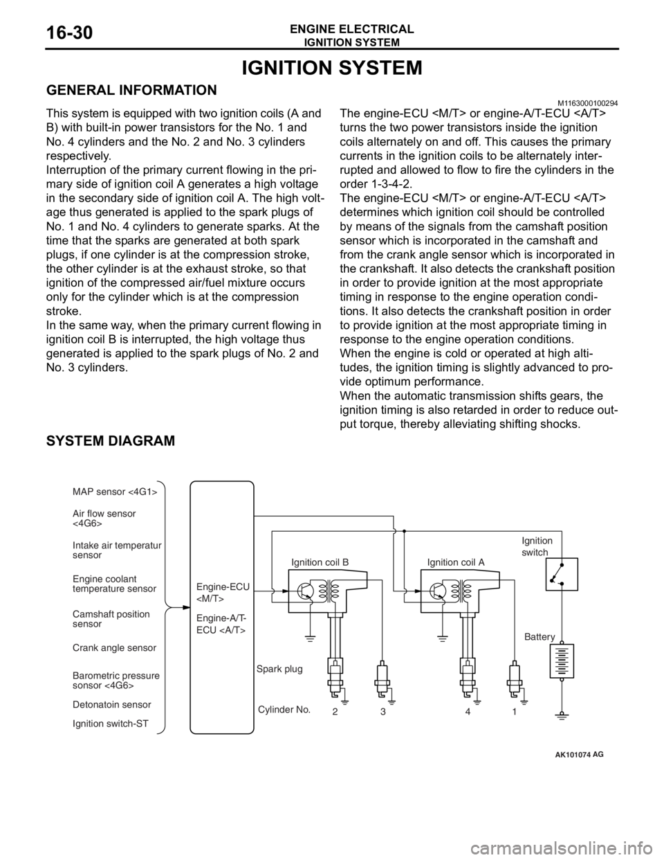
This system is equipped with two ignition coils (A and
B) with built-in power transistors for the No. 1 and
No. 4 cylinders and the No. 2 and No. 3 cylinders
respectively.
Interruption of the primary current flowing in the pri-
mary side of ignition coil A generates a high voltage
in the secondary side of ignition coil A. The high volt
-
age thus generated is applied to the spark plugs of
No. 1 and No. 4 cylinders to generate sparks. At the
time that the sparks are generated at both spark
plugs, if one cylinder is at the compression stroke,
the other cylinder is at the exhaust stroke, so that
ignition of the compressed air/fuel mixture occurs
only for the cylinder which is at the compression
stroke.
In the same way, when the primary current flowing in
ignition coil B is interrupted, the high voltage thus
generated is applied to the spark plugs of No. 2 and
No. 3 cylinders.
The engine-ECU
turns the two power transistors inside the ignition
coils alternately on and off. This causes the primary
currents in the ignition coils to be alternately inter
-
rupted and allowed to flow to fire the cylinders in the
order 1-3-4-2.
The engine-ECU
determines which ignition coil should be controlled
by means of the signals from the camshaft position
sensor which is incorporated in the camshaft and
from the crank angle sensor which is incorporated in
the crankshaft. It also detects the crankshaft position
in order to provide ignition at the most appropriate
timing in response to the engine operation condi
-
tions. It also detects the crankshaft position in order
to provide ignition at the most appropriate timing in
response to the engine operation conditions.
When the engine is cold or operated at high alti-
tudes, the ignition timing is slightly advanced to pro-
vide optimum performance.
When the automatic transmission shifts gears, the
ignition timing is also retarded in order to reduce out
-
put torque, thereby alleviating shifting shocks.
SYSTEM DIAGRAM
AK101074
Air flow sensor
<4G6> MAP sensor <4G1>
Intake air temperatur
sensor
Engine coolant
temperature sensor
Camshaft position
sensor
Crank angle sensor
Barometric pressure
sonsor <4G6>
Detonatoin sensor
Ignition switch-ST Engine-A/T-
ECU Engine-ECU
Ignition coil B
Cylinder No. 23 4
AG
1
Spark plug Ignition coil A
Ignition
switch
Battery
Page 108 of 800
ENGINE CONTROL
ENGINE AND EMISSION CONTROL17-2
ENGINE CONTROL
GENERAL INFORMATIONM1171000100277
A cable-type accelerator mechanical sus-
pended-type pedal has been adopted.
SERVICE SPECIFICATIONS
M1171000300088
ItemStandard value
Accel cable play mm1.0 ‚ąí 2.0
Engine idle speed r/min4G1750 ¬Ī 50
4G6750 ¬Ī 100
ON-VEHICLE SERVICE
ACCEL CABLE CHECK AND
ADJUSTMENT
M1171000900314
1. Turn A/C and lights OFF. Inspect and adjust at no load.
2. Warm engine until stabilized at idle.
3. Confirm idle speed is at standard value.
Standard value:
750 ¬Ī 50 r/min <4G1>
750 ¬Ī 100 r/min <4G6>
4. Stop engine. [ignition switch: LOCK (OFF)
position].
5. Confirm there are no sharp bends in the accelerator cable.
6. Check the inner cable for correct slack.
Standard value: 1.0 ‚ąí 2.0 mm
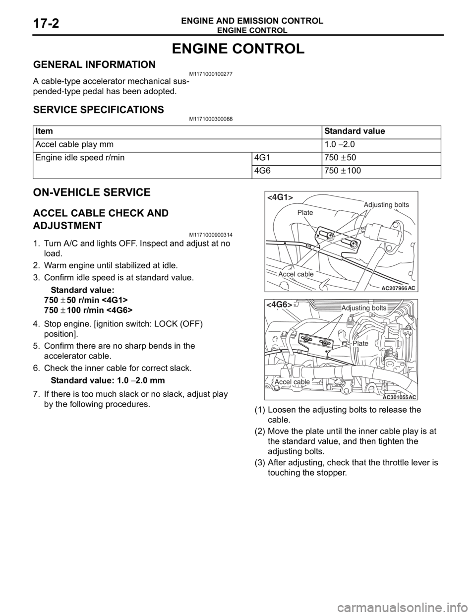
7. If there is too much slack or no slack, adjust play by the following procedures.
AC207966
Adjusting bolts
Plate
Accel cable
AC
<4G1>
AC301055
Adjusting bolts
Plate
Accel cable
AC
<4G6>
(1) Loosen th e adjusting bo lt s to re lease the
cab l e.
(2) M o v e th e pla t e until the inne r cab l e play is a t
the st andard value, an d then tighte n the
adjusting bo lt s.
(3) A f t e r adju s ting, check that the thro ttle leve r is
touching the stoppe r .
Page 283 of 800
WINDOW GLASS
BODY42-11
HANDLING OF AUTO WINDOW SEALER
Keep the sealant in a cool place, not exposed to the
direct rays of the sun. Do not place any heavy article
on the sealant nor press it, otherwise it will become
deformed. Avoid storing the sealant for more than 6
months, because it will lose its sealing effect.
BODY PINCH-WELD FLANGE SERVICING
Before servicing the body pinch-weld flange, remove
old adhesive completely. If the flange requires paint
-
ing, bake it after painting is completed.
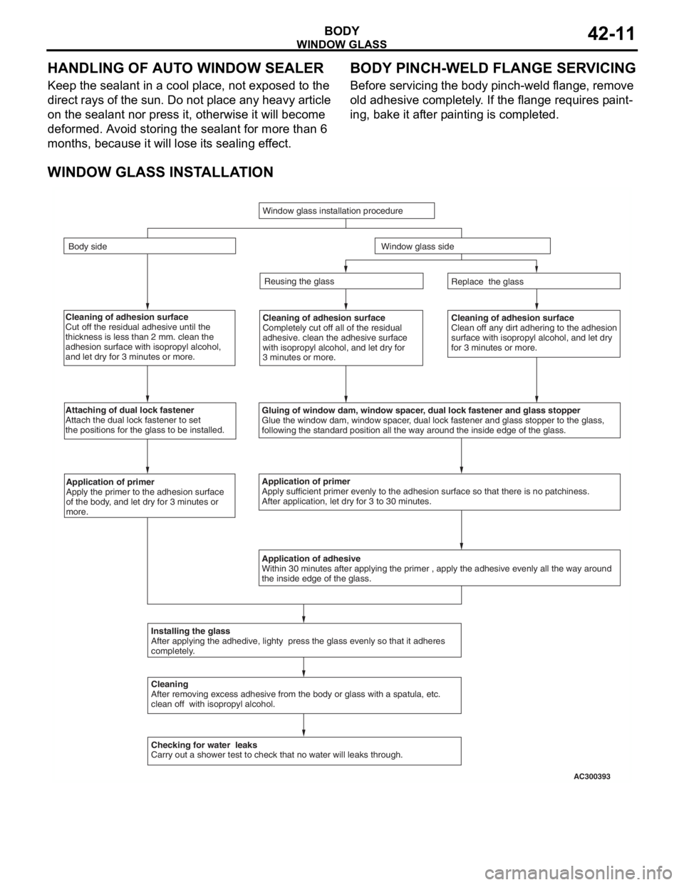
WINDOW GLASS INSTALLATION
Cleaning of adhesion surface
Cut off the residual adhesive until the
thickness is less than 2 mm. clean the
adhesion surface with isopropyl alcohol,
and let dry for 3 minutes or more.Cleaning of adhesion surface
Completely cut off all of the residual
adhesive. clean the adhesive surface
with isopropyl alcohol, and let dry for
3 minutes or more.Cleaning of adhesion surface
Clean off any dirt adhering to the adhesion
surface with isopropyl alcohol, and let dry
for 3 minutes or more.
Attaching of dual lock fastener
Attach the dual lock fastener to set
the positions for the glass to be installed.
Gluing of window dam, window spacer, dual lock fastener and glass stopper
Glue the window dam, window spacer, dual lock fastener and glass stopper to the glass,
following the standard position all the way around the inside edge of th\
e glass.
Application of primer
Apply the primer to the adhesion surface
of the body, and let dry for 3 minutes or
more.Application of primer
Apply sufficient primer evenly to the adhesion surface so that there is \
no patchiness.
After application, let dry for 3 to 30 minutes.
Application of adhesive
Within 30 minutes after applying the primer , apply the adhesive evenly \
all the way around
the inside edge of the glass.
Installing the glass
After applying the adhedive, lighty press the glass evenly so that it a\
dheres
completely.
Cleaning
After removing excess adhesive from the body or glass with a spatula, et\
c.
clean off with isopropyl alcohol.
Checking for water leaks
Carry out a shower test to check that no water will leaks through. Replace the glass
Reusing the glass
Window glass installation procedure
Body side
Window glass side
AC300393
Page 314 of 800
TRUNK LID
BODY42-42
3. If there is a difference in height between the side outer panels and the side edges of the trunk lid
panel assembly, check the trunk lid hinges and, if
necessary, replace them
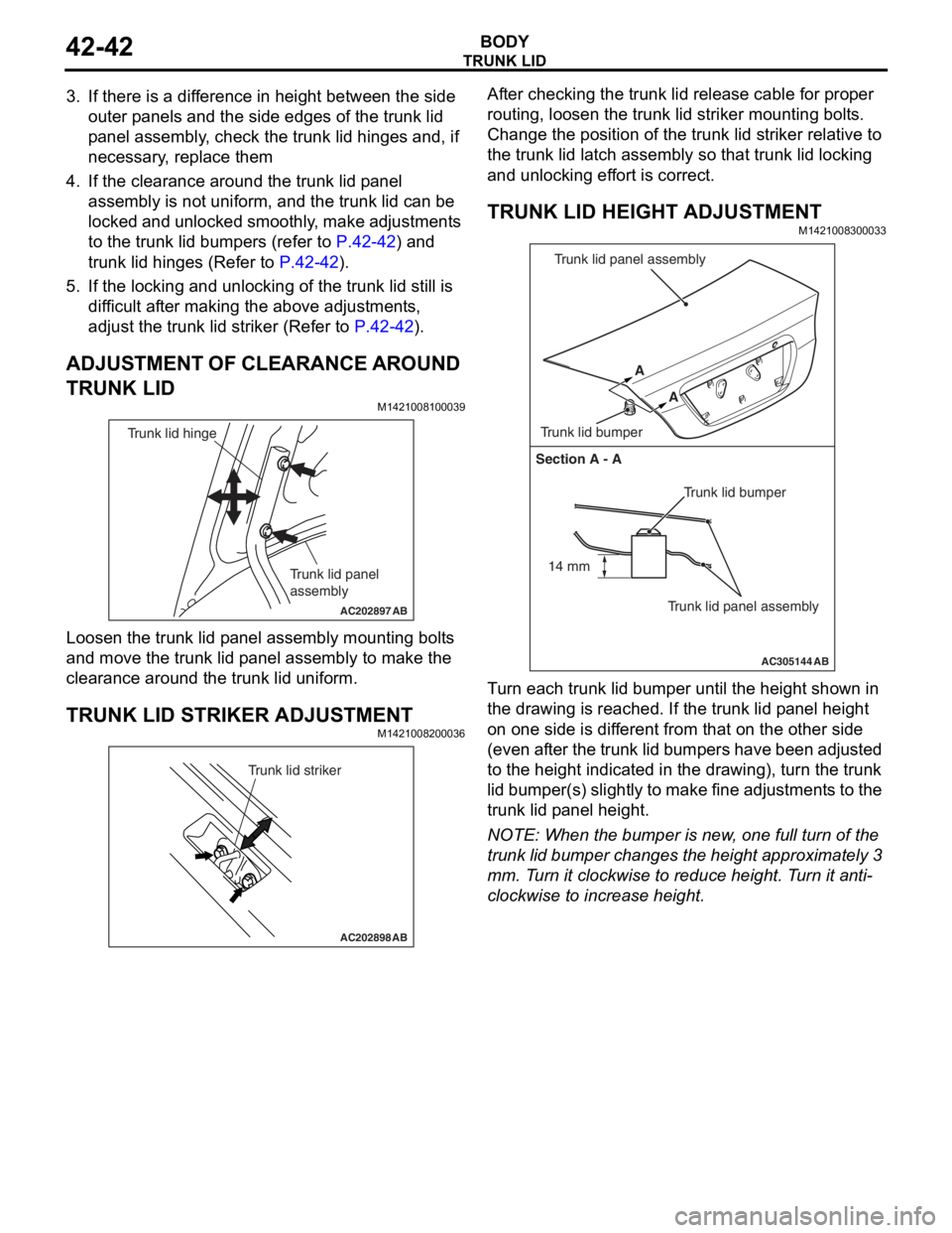
4. If the clearance around the trunk lid panel assembly is not uniform, and the trunk lid can be
locked and unlocked smoothly, make adjustments
to the trunk lid bumpers (refer to
P.42-42) and
trunk lid hinges (Refer to P.42-42).
5. If the locking and unlocking of the trunk lid still is difficult after making the above adjustments,
adjust the trunk lid striker (Refer to
P.42-42).
ADJUSTMENT OF CLEARANCE AROUND
TRUNK LID
M1421008100039
AC202897
Trunk lid panel
assembly
Trunk lid hinge
AB
Loosen the trunk lid p a nel a sse mbly mounting bolt s
and move
the trun k lid p anel assembly to make t he
clea
rance aroun d the t r unk lid u n iform.
TRUNK LID STRIKER ADJUSTMENT
M14210082 0003 6
AC202898
Trunk lid striker
AB
After checking the trunk lid relea s e cable for pro per
routin
g, lo osen the trun k lid striker mo untin g bolt s .
Ch
ange th e position of t he trunk lid st rike r relat i ve to
the trun
k lid la tch a s sembly so tha t trunk lid lockin g
and un
lockin g ef f o rt is corre ct.
TRUNK LID HEIGHT ADJUSTMENT
M14210083 0003 3
AC305144
Section A - A
Trunk lid bumper
Trunk lid panel assembly
A
A
Trunk lid bumper Trunk lid panel assembly
AB
14 mm
T
u rn each trun k lid bumper u n til the he ight shown in
the dra
w ing is reached. If the t r unk lid p a n e l he ight
on one
sid e is dif f erent from that on the oth e r side
(even
a f t e r th e t r un k lid bu mp ers have be en ad ju st ed
to the h
e igh t ind i ca ted in the dra w ing), tu rn the trunk
lid bumper(s)
slight ly to make fine adjustment s to the
trunk lid p
a nel h e ight .
NOTE: Whe n the b u mpe r is new , one full turn o f the
trunk lid bumper ch anges t he height appro x imately 3
mm.
T
u
rn it clockwise to r educe height. T u rn it anti
-
clockwise to increase height.
Page 329 of 800
ACX00571
M.U.T.-II connectedWithin 10 seconds
Hazard
warning
switch ON
OFF 1
23
45
6
AB
KEYLE SS ENTR Y SYSTEM
BOD Y42-57
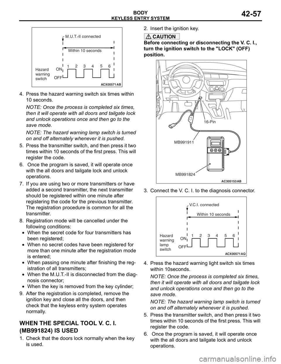
4.Press th e hazard warning switch six times within
10 seconds.
NOTE: Once th e process is comple ted six t i me s,
th
en it
will operate with al l do ors an d t a ilgate lock
an
d unlock opera t ions once and then go to th e
save
mode .
NOTE: The h a zard warnin g lamp switch is turned
on
and o ff alt e rnately when ever it is pushed.
5.Pre s s th e tr ansmitter switch, a nd then pre s s it two
t i mes within 10 second s of th e f i rst pre s s. This will
reg i st er the code.
6. Once the p r ogram is saved, it will opera t e once
wit h the a ll d oors a nd t a ilgate lock and unlo ck
op erations.
7.If you a r e using t w o or mo re transmitters or have
ad ded a second tra n smitter , the n e xt tra n smitter
should be re gistered within o ne minute af ter
reg i st ering the code fo r the pre v io us tra n smitter .
Th e registration pr oced ure is co mmo n for a ll th e
tra n smitter .
8.Registra tion mode will be ca ncelled under the
fo llowing condit i ons:
‚ÄĘWhen the secr et co de for fo ur transmitters has
bee
n registere d ;
‚ÄĘWhen no secre t cod e s h a ve b een re gist ered fo r
more tha
n one minute af ter the registration mode
is ente
r ed;
‚ÄĘWhen p a ssing o ne minute af ter fin i sh ing t he reg-
istration of all t r ansmitte rs;
‚ÄĘWhen the M.U.T . -II is d i sconne cted from th e dia g-
nosis connecto r;
‚ÄĘWhen the key is re moved fro m the key cylin der;
9.Af ter the registration is completed, remove the
ignition key a nd close all the d oors, and th en
check tha t the keyless entry syste m op erates
no rmally .
WH EN THE SPECIAL T O OL V . C. I.
(
M B991824) I S USED
1.Check t hat the doors lock n o rmally wh en the key
is used.
2. In sert t he ig nition ke y .
CAUTION
Before connecting or disconnecting the V. C. I.,
turn the ignition switch to the "LOCK" (OFF)
position.
AC305153AB
MB991911
MB991824
16-Pin
3. Connect the V. C. I. to the diagnosis connector.
ACX00571
Within 10 seconds
Hazard
warning
lamp
switch ON
OFF 1234 56
AQ
V.C.I. connected
4. Press the hazard warning
light switch six times
within 10seconds.
NOTE: Once the process is completed six times,
then it will operate with all doors and tailgate lock
and unlock operations once and then go to the
save mode.
NOTE: The hazard warning lamp switch is turned
on and off alternately whenever it is pushed.
5. Press the transmitter switch, and then press it two times within 10 seconds of the first press. This will
register the code.
6. Once the program is saved, it will operate once with the all doors and tailgate lock and unlock
operations.
Page 466 of 800
90-2
TAIL LAMP, POSITION LAMP,
LICENCE PLATE LAMP AND
LIGHTING MONITOR BUZZER
TAIL LAMP, POSITION LAMP, LICENCE
PLATE LAMP AND LIGHTING MONITOR
BUZZER
TAIL LAMP, POSITION LAMP, LICENCE
PLATE LAMP AND LIGHTING MONITOR
BUZZER
FRONT FOG LAMP
FRONT FOG LAMP
FRONT FOG LAMP
ROOM LAMP AND LUGGAGE
COMPARTMENT LAMP
ROOM LAMP AND LUGGAGE
COMPARTMENT LAMP
ROOM LAMP AND LUGGAGE
COMPARTMENT LAMP
ROOM LAMP,PERSONAL LAMP
AND LUGGAGE ROOM LAMP
ROOM LAMP, PERSONAL LAMP AND
LUGGAGE ROOM LAMP
ROOM LAMP, PERSONAL LAMP AND
LUGGAGE ROOM LAMP
REAR FOG LAMP
REAR FOG LAMP
REAR FOG LAMP
HEADLAMP LEVELLING SYSTEM
HEADLAMP LEVELLING SYSTEM
HEADLAMP LEVELLING SYSTEM
TURN-SIGNAL LAMP AND HAZARD
WARNING LAMP
TURN SIGNAL LAMP AND HAZARD
WARNING LAMP
TURN SIGNAL LAMP AND HAZARD
WARNING LAMP
BACK-UP LAMP
BACK-UP LAMP
BACK-UP LAMP
STOP LAMP
STOP LAMP
STOP LAMP
STOP LAMP
STOP LAMP
HORN . . . . . . . . . . . . . . . . . . . . . . . . .90-186
METER AND GAUGE
METER AND GAUGE
METER AND GAUGE
FUEL WARNING LAMP, OIL
PRESSURE WARNING LAMP AND
BRAKE WARNING LAMP
FUEL WARNING LAMP, OIL PRESSURE
WARNING LAMP AND BRAKE WARNING
LAMP
FUEL WARNING LAMP, OIL PRESSURE
WARNING LAMP AND BRAKE WARNING
LAMP
POWER WINDOWS
POWER WINDOWS
Continued on next page
Page 470 of 800
J/C
CIRCUIT DIAGRAMS90-6
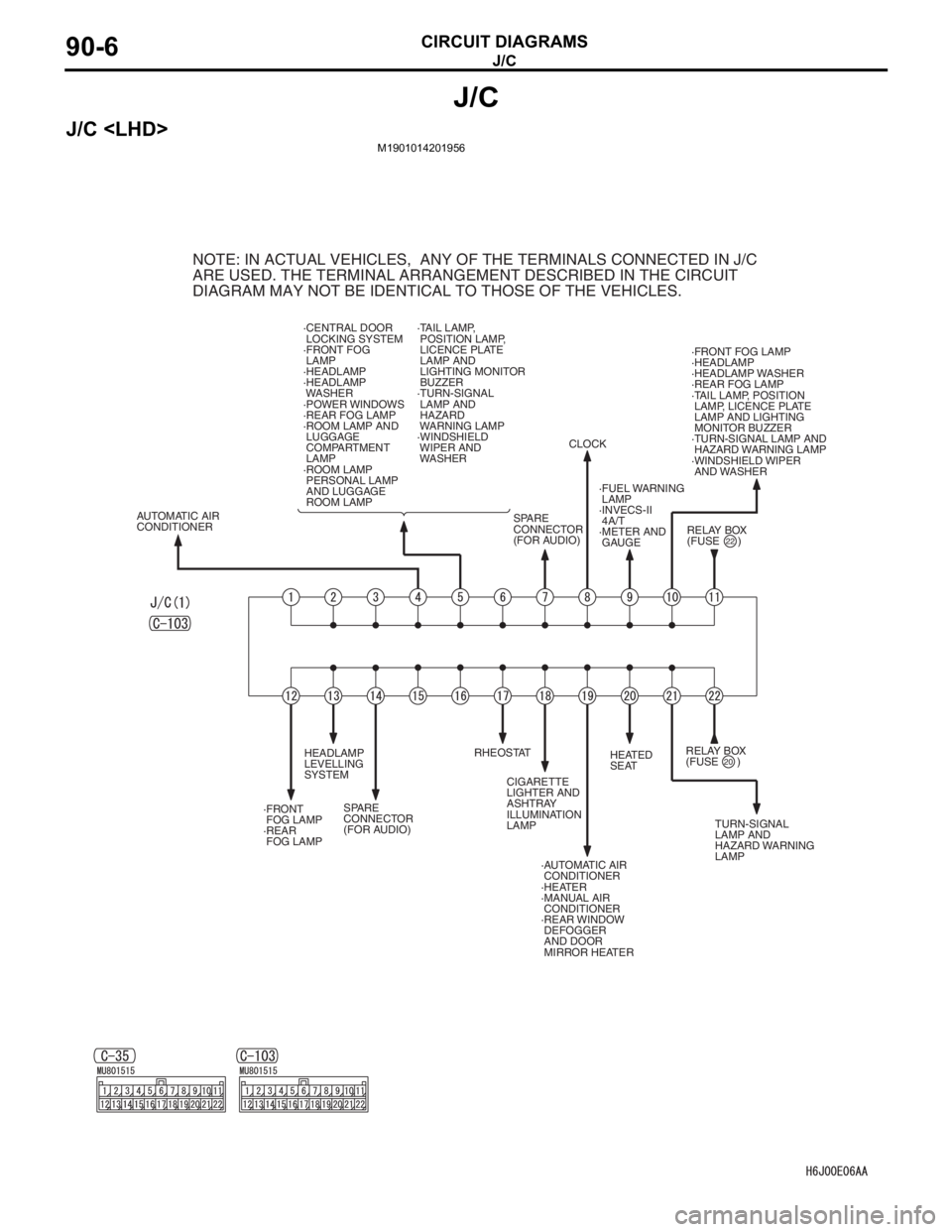
J/C
J/C
NOTE: IN ACTUAL VEHICLES, ANY OF THE TERMINALS CONNECTED IN J/C
ARE USED. THE TERMINAL ARRANGEMENT DESCRIBED IN THE CIRCUIT
DIAGRAM MAY NOT BE IDENTICAL TO THOSE OF THE VEHICLES.
·CENTRAL DOOR
LOCKING SYSTEM
·FRONT FOG
LAMP
·HEADLAMP
·HEADLAMP
WASHER
·POWER WINDOWS
·REAR FOG LAMP
·ROOM LAMP AND
LUGGAGE
COMPARTMENT
LAMP
·ROOM LAMP
PERSONAL LAMP
AND LUGGAGE
ROOM LAMP ·TAIL LAMP,
POSITION LAMP,
LICENCE PLATE
LAMP AND
LIGHTING MONITOR
BUZZER
·TURN-SIGNAL
LAMP AND
HAZARD
WARNING LAMP
·WINDSHIELD
WIPER AND
WASHER
RELAY BOX
(FUSE )·FRONT FOG LAMP
·HEADLAMP
·HEADLAMP WASHER
·REAR FOG LAMP
·TAIL LAMP, POSITION
LAMP, LICENCE PLATE
LAMP AND LIGHTING
MONITOR BUZZER
·TURN-SIGNAL LAMP AND
HAZARD WARNING LAMP
·WINDSHIELD WIPER
AND WASHER
SPARE
CONNECTOR
(FOR AUDIO)CLOCK
·FUEL WARNING
LAMP
·INVECS-II
4A/T
·METER AND
GAUGE
RELAY BOX
(FUSE )
TURN-SIGNAL
LAMP AND
HAZARD WARNING
LAMP HEATED
SEAT
·AUTOMATIC AIR
CONDITIONER
·HEATER
·MANUAL AIR
CONDITIONER
·REAR WINDOW
DEFOGGER
AND DOOR
MIRROR HEATER CIGARETTE
LIGHTER AND
ASHTRAY
ILLUMINATION
LAMP RHEOSTAT
SPARE
CONNECTOR
(FOR AUDIO) HEADLAMP
LEVELLING
SYSTEM
·FRONT
FOG LAMP
·REAR
FOG LAMP
20
22
AUTOMATIC AIR
CONDITIONER
Page 471 of 800
J/C
CIRCUIT DIAGRAMS90-7
REAR WIPER
AND WASHER
·FRONT FOG LAMP
·HEADLAMP
·HEADLAMP WASHER
·REAR FOG LAMP
·TAIL LAMP, POSITION
LAMP, LICENCE PLATE
LAMP AND LIGHTING
MONITOR BUZZER
·WINDSHIELD WIPER
AND WASHERINVECS-II
4A/T POWER
WINDOWSSTOP
LAMP·INVECS-II
4A/T
·REAR WIPER
AND WASHER
·STOP LAMP
·FRONT FOG LAMP
·HEADLAMP
·HEADLAMP WASHER
·REAR FOG LAMP
·REAR WIPER
AND WASHER
·TAIL LAMP, POSITION
LAMP, LICENCE PLATE
LAMP AND LIGHTING
MONITOR BUZZER
·TURN-SIGNAL LAMP
AND HAZARD
WARNING LAMP
·WINDSHIELD WIPER
AND WASHER·FRONT FOG LAMP
·HEADLAMP
·HEADLAMP WASHER
·POWER WINDOWS
·REAR FOG LAMP
·REAR WIPER
AND WASHER
·TAIL LAMP, POSITION
LAMP, LICENCE PLATE
LAMP AND LIGHTING
MONITOR BUZZER
·TURN-SIGNAL LAMP
AND HAZARD
WARNING LAMP
·WINDSHIELD WIPER
AND WASHER·FRONT FOG LAMP
·HEADLAMP
·HEADLAMP LEVELLING
SYSTEM
·HEADLAMP WASHER
·REAR FOG LAMP
·TAIL LAMP, POSITION
LAMP, LICENCE PLATE
LAMP AND LIGHTING
MONITOR BUZZER
·WINDSHIELD WIPER
AND WASHER
·AUTOMATIC AIR
CONDITIONER
·HEATER
·MANUAL AIR
CONDITIONER
J/B (FUSE ) HEATED
SEAT ·HEADLAMP
LEVELLING
SYSTEM
·WINDSHIELD
WIPER AND
WASHER
REMOTE
CONTROLLED
MIRROR ·HEADLAMP
·HEADLAMP
WASHER
5