rocker cover MITSUBISHI LANCER 2006 Workshop Manual
[x] Cancel search | Manufacturer: MITSUBISHI, Model Year: 2006, Model line: LANCER, Model: MITSUBISHI LANCER 2006Pages: 800, PDF Size: 45.03 MB
Page 54 of 800
AC303619
4.0 ± 1.0 N·m
4.0 ± 1.0 N·m10*
9* 4
1* 5
11
12 ± 1 N·m 9.0 ± 1.0 N·m
9.0 ± 1.0 N·m
AB
12 ± 1 N·m
Clamp
8*
3*
<4G6>
6
7
N
2
8.8 ± 1.0 N·m
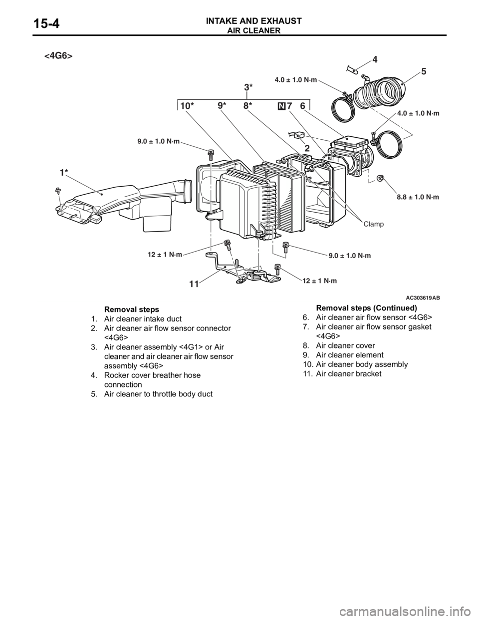
Removal steps
1.Air cleaner intake duct
2.Air cleaner air flow sensor connector
<4G6>
3.Air cleaner assembly <4G1> or Air
cleaner and air cleaner air flow sensor
assembly <4G6>
4.Rocker cover breather hose
connection
5.Air cleaner to throttle body duct
6.Air cleaner air flow sensor <4G6>
7.Air cleaner air flow sensor gasket
<4G6>
8.Air cleaner cover
9.Air cleaner element
10.Air cleaner body assembly
11 .Air cleaner bracket
AIR CLEA NER
INTAKE AN D EXHAU ST15-4
Removal steps (Continued)
Page 101 of 800
IGNITION SYSTEM
ENGINE ELECTRICAL16-39
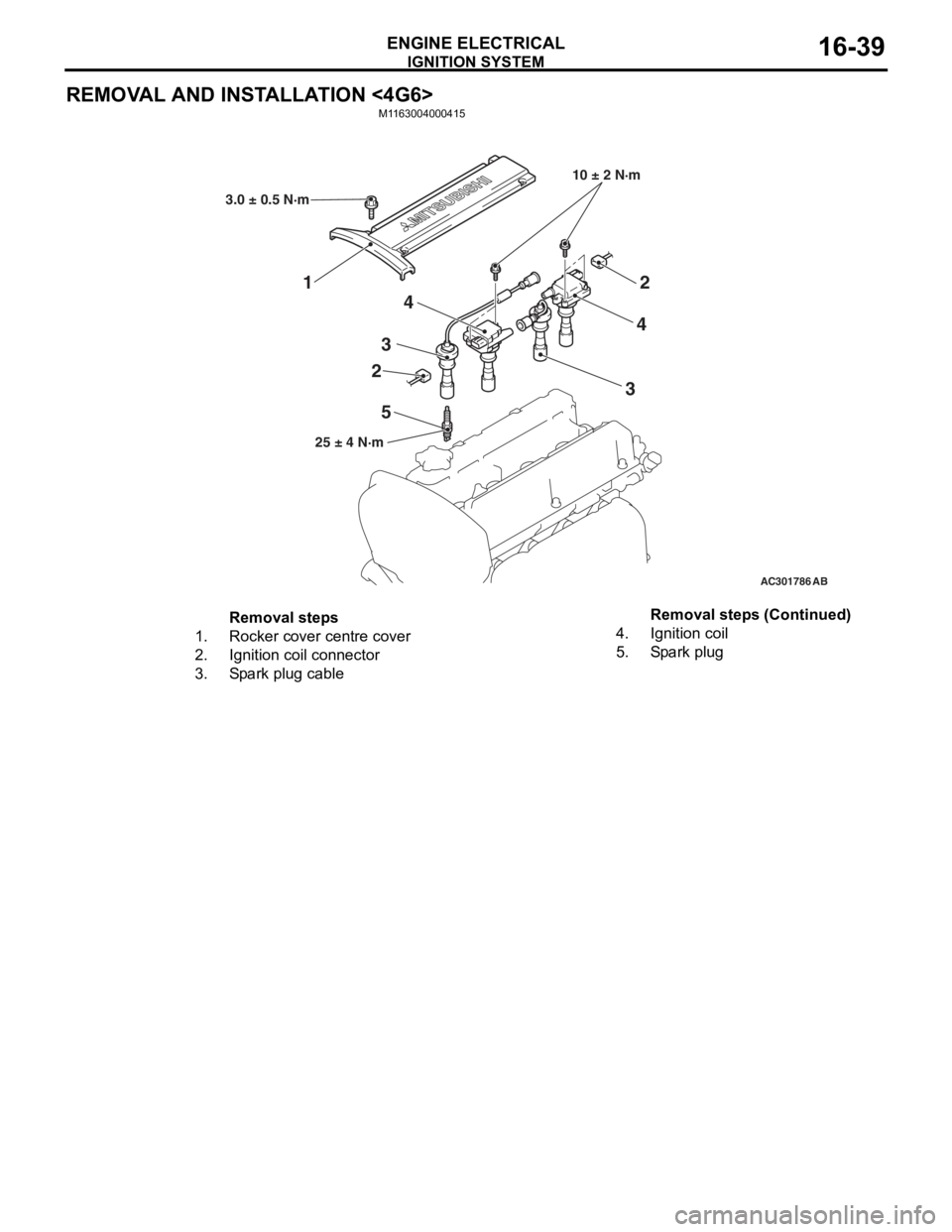
REMOVAL AND INSTALLATION <4G6>
M1163004000415
AC301786
10 ± 2 N·m
25 ± 4 N·m
5 4
2 2
3
3
4
AB
1
3.0 ± 0.5 N·m
Removal steps
1.Rocker cover centre cover
2.Ignition coil connector
3.Spark plug cable
4.Ignition coil
5.Spark plug
Removal steps (Continued)
Page 104 of 800
IGNITION SYSTEM
ENGINE ELECTRICAL16-42
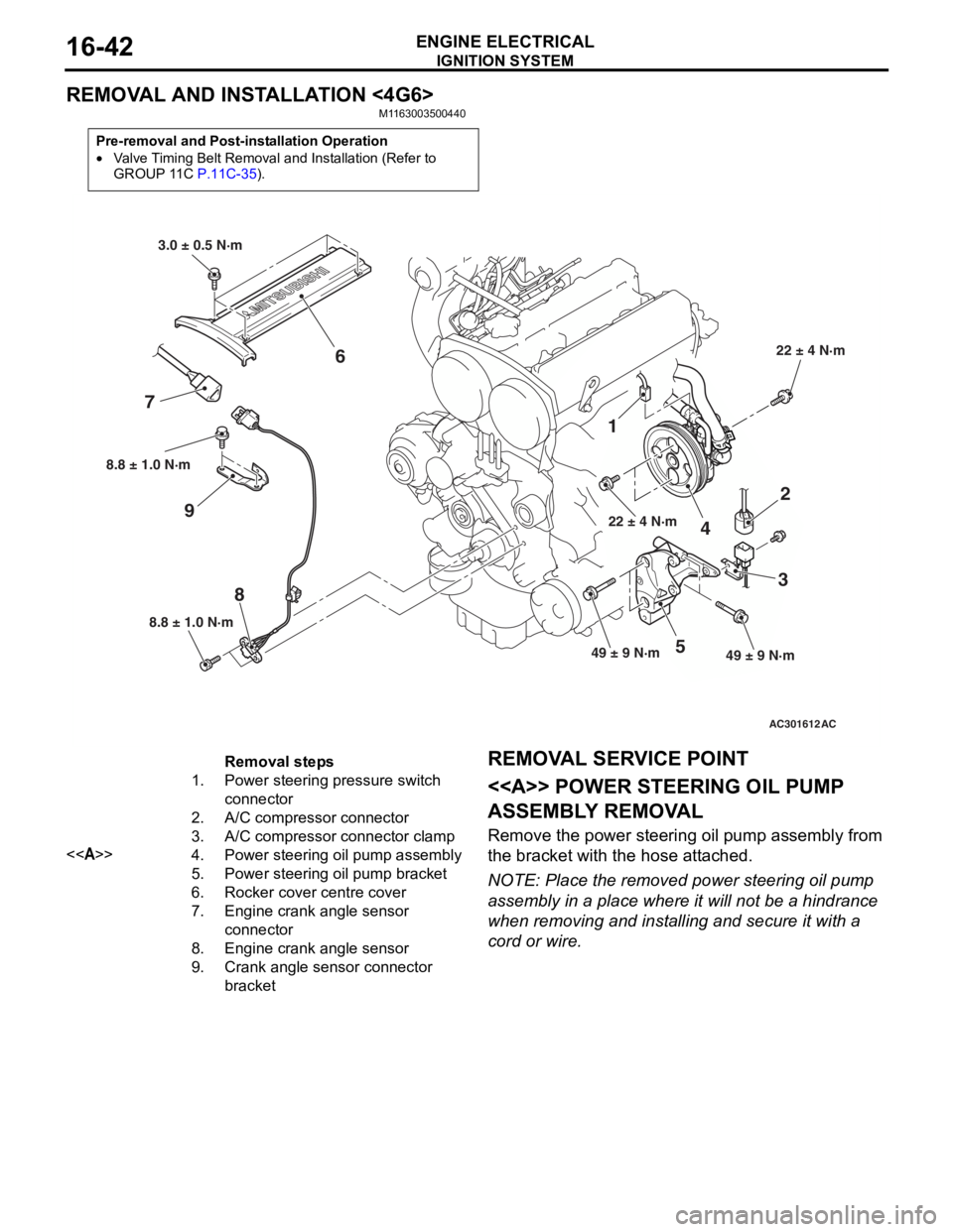
REMOVAL AND INSTALLATION <4G6>
M1163003500440
Pre-removal and Post-installation Operation
•Valve Timing Belt Removal and Installation (Refer to
GROUP 11C P.11C-35).
AC301612
8.8 ± 1.0 N·m
8
8.8 ± 1.0 N·m
9
1
22 ± 4 N·m
4
2
3
49 ± 9 N·m49 ± 9 N·m5
22 ± 4 N·m
3.0 ± 0.5 N·m
6
7
AC
Removal steps
1.Power steering pressure switch
connector
2.A/C compressor connector
3.A/C compressor connector clamp
<>4.Power steering oil pump assembly
5.Power steering oil pump bracket
6.Rocker cover centre cover
7.Engine crank angle sensor
connector
8.Engine crank angle sensor
9.Crank angle sensor connector
bracket
REMOV A L SER VICE POINT
<> POWE R STEERING OIL PUMP
ASSEMBL
Y REMOV A L
Remove the p o wer st eering oil pump assembly from
the bra
cke t with th e hose att a ched.
NOTE: Place the remo ved power st eering oil pump
assembly in a place where it will not be a hindrance
wh
en removing an d inst a lling an d secure it with a
cord or wire.
Page 115 of 800
EMISSION CONTROL
ENGINE AND EMISSION CONTROL17-9
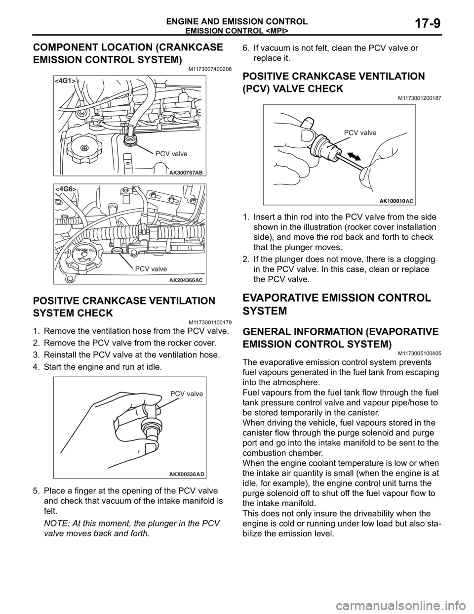
COMPONENT LOCATION (CRANKCASE
EMISSION CONTROL SYSTEM)
M1173007400208
AK300767
<4G1>
AB
PCV valve
AK204366
<4G6>
AC
PCV valve
POSITIVE CRANKCASE VENTILATION
SYSTEM CHECK
M11 7300 1 1 0017 9
1.Remove the ventilatio n hose from the PCV valve.
2.Remove the PCV valve from t he rocker cove r .
3.Reinst all the PCV valve at the ven t ila tion h o se.
4.S t art the engin e and run at idle .
AKX00336
PCV valve
AD
5.Pla c e a fing er at the open ing o f the PCV va lve
an d ch eck that vacu um o f the int a ke manifold is
fe lt.
NOTE: At this mo men t, the p l unge r in t he PCV
valve mo ves back an d forth.
6.If vacuum is not felt, clean t he PCV valve o r
re place it.
POSITIVE CRANKCASE VENTILA TION
(
P CV) V A L VE CHECK
M1173 0012 0018 7
AK100010
PCV valve
AC
1.In sert a thin rod in to the PCV valve from the side
shown in the illu strat i on (ro cke r cover in st allation
side) , and move the ro d back an d forth to ch eck
th at the plung er mo ves.
2.If the plunger does not move , there is a clo ggin g
in the PCV valve. In th is case, clean o r repla c e
th e PCV valve.
EVAPORA T IVE EMISSION CONTROL
SYSTEM
GENERAL INFORMA T ION (EV A PORA TIVE
EMISSION CONTROL SYSTEM)
M1173 0051 0040 5
The evaporat ive emission contro l syste m pre v ent s
f
uel vapours generat ed in t he fuel t ank from escaping
into t
he atmosp here.
Fuel vapours fro m the fuel t a n k flow throug h the f uel
t
a n k pre ssu re co ntrol valve an d vap our pipe/ho se to
be st
ored te mpora r ily in t he ca nister .
When dr iving the veh i cle, fue l va pours stor ed in the
canister
flow thro ugh th e purge solenoid and purge
port an
d go into the int a ke ma nifold to b e sen t to th e
combust
i on chamber .
When the eng ine co ola n t te mp eratu r e is low o r when
the int
a ke air q uantity is small (wh en the engine is at
idle
, for example), t he eng ine contro l unit turns the
purge sole
noid of f to shu t of f the fue l va pour flow to
the in
t a ke manif o ld.
This does not on ly insure the driveability when t he
engin
e is cold or runn ing und er low load b u t also st a
-
bilize the emissio n level.
Page 398 of 800
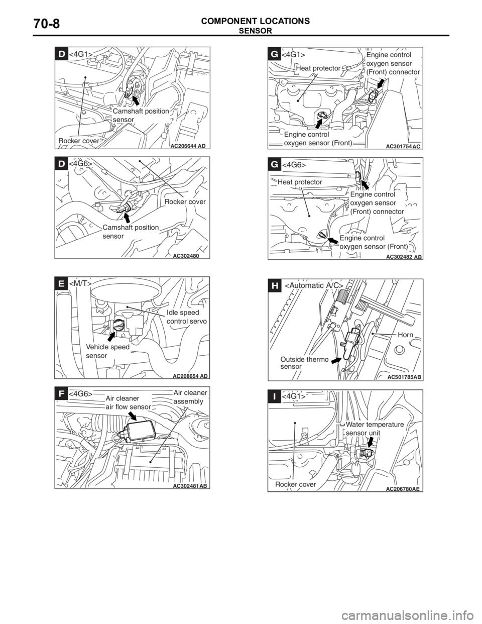
AC206644AD
Camshaft position
sensor
D<4G1>
Rocker cover
AC302480AB
D
Camshaft position
sensor
Rocker cover
<4G6>
AC208654
AD
E
Vehicle speed
sensor
Idle speed
control servo
AC302481AB
FAir cleaner
assembly<4G6>Air cleaner
air flow sensor
AB
AC301754
G<4G1>
AC
Heat protector
Engine control
oxygen sensor (Front)
Engine control
oxygen sensor
(Front) connector
AC302482
G
AB
Heat protector
<4G6>
Engine control
oxygen sensor
(Front) connector
Engine control
oxygen sensor (Front)
AC501785AB
H
Horn
Outside thermo
sensor
AC206780 AE
I
Rocker cover
<4G1>
Water temperature
sensor unit
SE
NSOR
COMPONENT LOCA TIONS70-8
Page 399 of 800

AC501828AB
I
Rocker cover
<4G6>
Water temperature
sensor unit
AC206775AF
J
Input shaft
speed sensor
Output shaft
speed sensor
Air cleaner
bracket
AC501788AB
K
Inside air
temperature
sensor
AC501789
AB
L
Photo sensor
AC501786
AB
M
Air thermo
sensor
Heater unit
AC501787AB
M
Air thermo
sensor
Heater
unit
Heater water
temperature
sensor
AC300517 AJ
N
Side impact
sensor (Front)
Centre
pillar
AC300534
AI
O
Side impact
sensor (Rear)
Rear
seat belt
SENSOR
COMPONENT LOCA TIONS70-9
Page 408 of 800
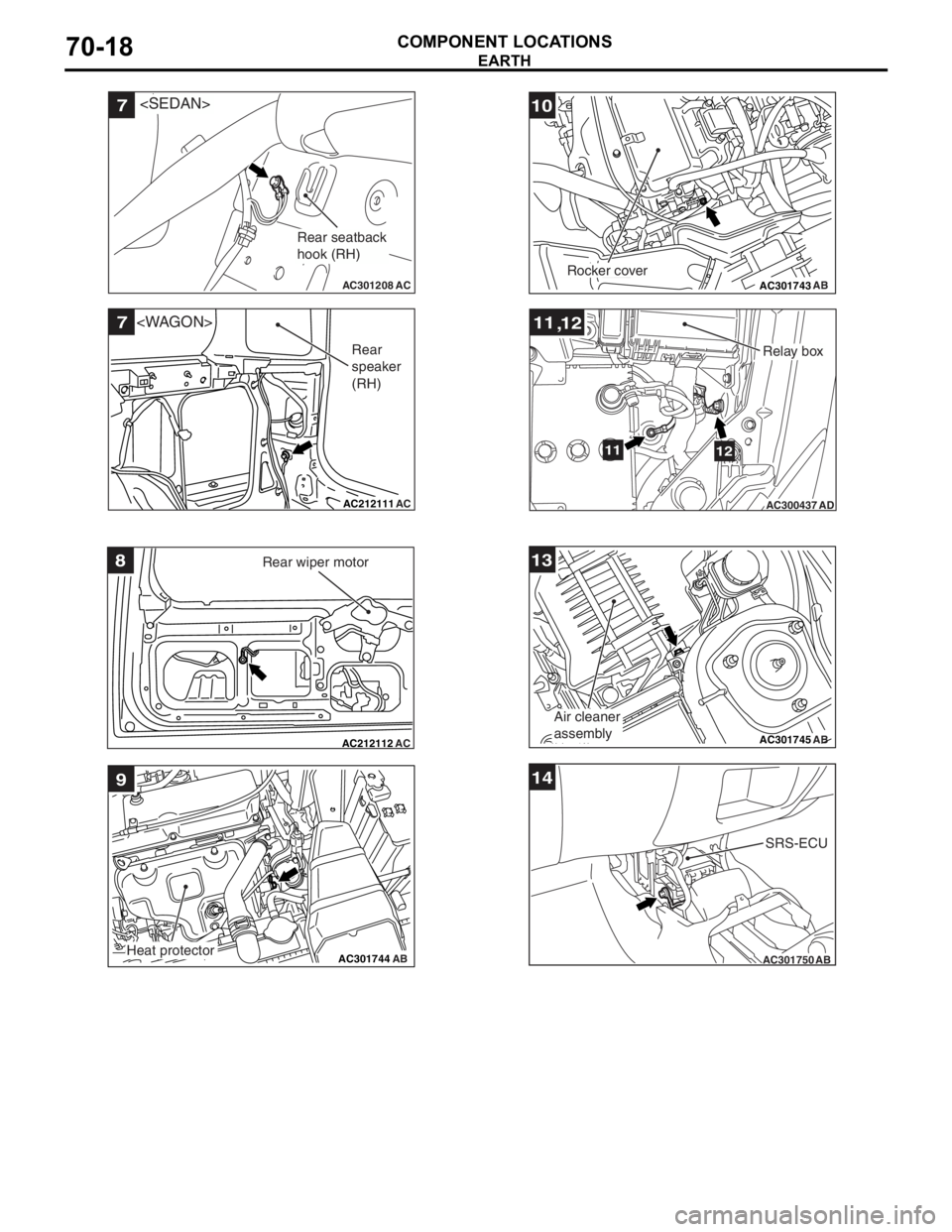
AC301208
7
AC
Rear seatback
hook (RH)
AC212111
7
AC
Rear
speaker
(RH)
AC212112AC
8Rear wiper motor
AC301744AB
9
Heat protector
AC301743AB
10
Rocker cover
AC300437
1112
,
1112
AD
Relay box
AC301745
13
AB
Air cleaner
assembly
AC301750AB
14
SRS-ECU
EARTH
COMPONENT LOCA TIONS70-18