seat MITSUBISHI LANCER 2006 Workshop Manual
[x] Cancel search | Manufacturer: MITSUBISHI, Model Year: 2006, Model line: LANCER, Model: MITSUBISHI LANCER 2006Pages: 800, PDF Size: 45.03 MB
Page 121 of 800
EMISSION CONTROL
ENGINE AND EMISSION CONTROL17-15
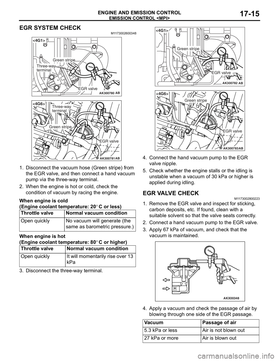
EGR SYSTEM CHECK
M1173002600348
AK300780AB
<4G1>
EGR valve
Green stripe
Three-way
terminal
AK300781AB
<4G6>
EGR valve
Green stripe
Three-way
terminal
1.Disco nnect the vacu um ho se (Green stripe) from
th e EGR valve, a nd th en connect a hand vacuum
pu mp via t he thre e-way te rmin al.
2.Wh en the engine is hot o r cold, check the
condition of va cuum by racing the engine.
When engine is c o ld
(Eng ine coo lant tem perature: 20°C or less)
Throttle valveNormal vacuum co ndition
Open quicklyNo va cuum will gene rate (th e
same as baro
m etric pre s sure.)
When engine is h o t
(Eng ine coo lant tem perature: 80°C or higher)
Throttle valveNormal vacuum c ondition
Open quicklyIt will mo me nt a r i l y rise o v er 13
kPa
3.Disco nnect the th ree-way t e rminal.
AK300782AB
<4G1>
EGR valve
Green stripe
AK300783AB
<4G6>
EGR valve
Green stripe
4.Conn ect the han d va cuum pump to t he EGR
valve nipple.
5.Check whe t her th e engine st alls or the idling is
u n st able when a vacuum of 30 kPa or h i gher is
a pplied during idling.
EGR V A L V E CHECKM1173 0028 0022 3
1.Remove the EGR valve an d inspect for stickin g ,
carbon deposit s, e t c. If found , clean with a
suit able so lve n t so that th e va lve seat s corre ctly .
2.Conn ect a hand vacuum pump to the EGR va lve .
3.App l y 6 7 kPa of va cuum, and check t hat the
vacu um is maint a ined.
AKX00348
4.App l y a vacuum and chec k th e p a ssage of air by
b l owing throug h one side of the EGR p a ssage.
VacuumPassage of air
5.3 kPa or lessAir is not blown out
27 kPa or moreAir is blown out
Page 144 of 800
FRONT AXLE HUB ASSEMBLY
FRONT AXLE26-12
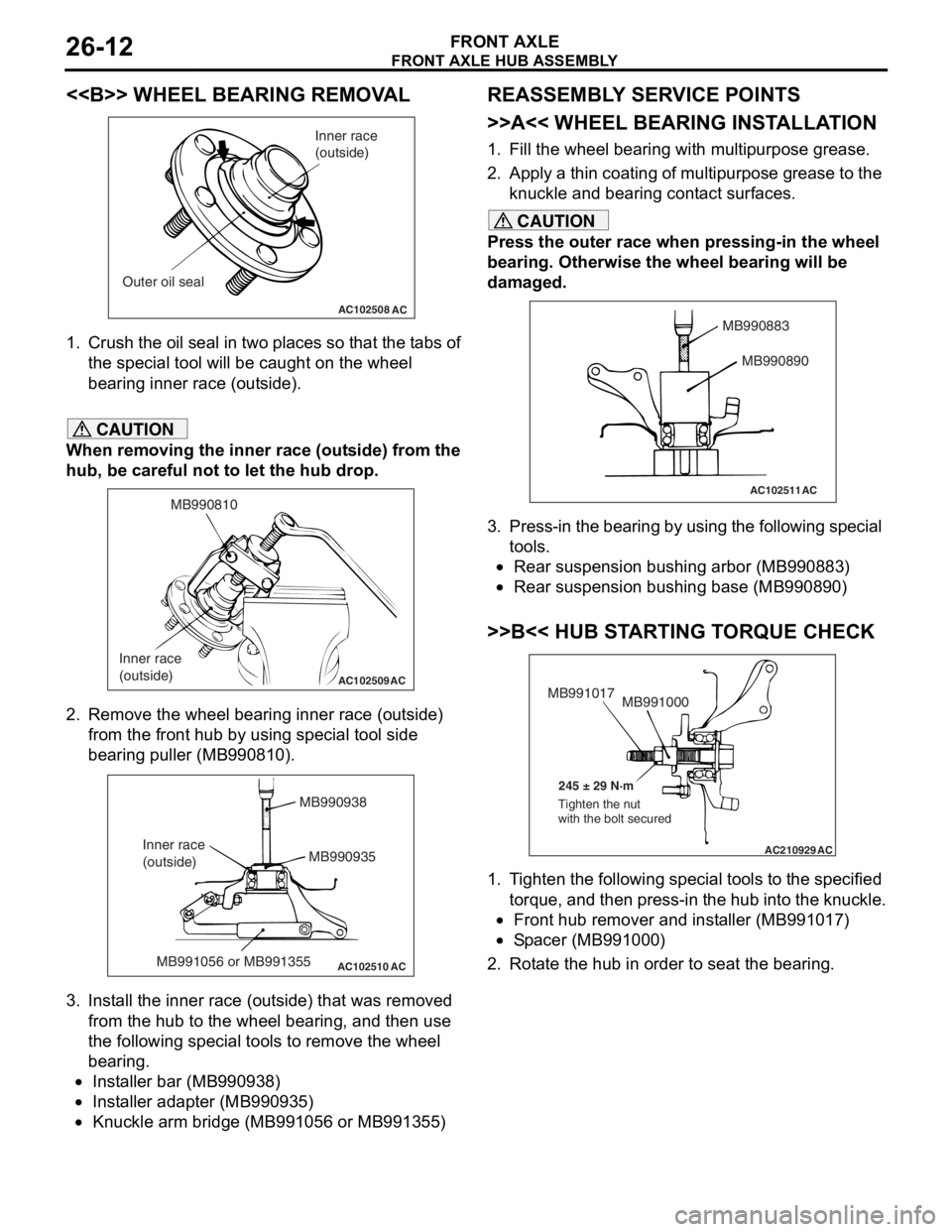
<> WHEEL BEARING REMOVAL
AC102508AC
Inner race
(outside)
Outer oil seal
1. Crush th e oil seal in two pl ace s so t hat t he t abs of
th e spe c ia l too l will be caugh t on th e wheel
be aring inne r race (out side).
CAUTION
When removing the inner race (outside) from the
hub, be careful not to let the hub drop.
AC102509
MB990810
Inner race
(outside)
AC
2. Remove the wheel bearing inner race (outside) from the front hub by using special tool side
bearing puller (MB990810).
AC102510 AC
MB990938
MB990935
MB991056 or MB991355
Inner race
(outside)
3. Install the inner race (outside) that was removed
from the hub to the wheel bearing, and then use
the following special tools to remove the wheel
bearing.
•Installer bar (MB990938)
•Installer adapter (MB990935)
•Knuckle arm bridge (MB991056 or MB991355)
REASSEMBLY SERVICE POINTS
>>A<< WHEEL BEARING INSTALLATION
1. Fill the wheel bearing with multipurpose grease.
2. Apply a thin coating of multipurpose grease to the knuckle and bearing contact surfaces.
CAUTION
Press the outer race when pressing-in the wheel
bearing. Otherwise the wheel bearing will be
damaged.
AC102511
MB990883
MB990890
AC
3. Press-in the bearing by using the following special tools.
•Rear suspension bushing arbor (MB990883)
•Rear suspension bushing base (MB990890)
>>B<< HUB STARTING TORQUE CHECK
AC210929AC
MB991000
MB991017
245 ± 29 N·m
Tighten the nut
with the bolt secured
1. Tighten the following special tools to the specified torque, and then press-in the hub into the knuckle.
•Front hub remover and installer (MB991017)
•Spacer (MB991000)
2. Rotate the hub in order to seat the bearing.
Page 160 of 800
ON-VEHICLE SERVICE
REAR AXLE27-4
ON-VEHICLE SERVICE
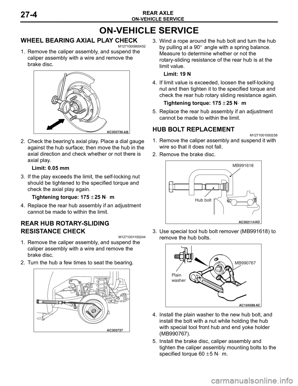
WHEEL BEARING AXIAL PLAY CHECKM1271000900452
1. Remove the caliper assembly, and suspend the caliper assembly with a wire and remove the
brake disc.
AC303736AB
2.Check the be aring ' s axial play . Place a dial gau ge
ag ainst th e hub su rface; then mo ve t he hu b in the
axial dire ction and check whe t her or not the r e is
axial pla y .
Limit: 0.05 mm
3.If the play e xce eds the limit, the self -lockin g nut
should be tighte ned to the specified torque and
check the axial play again .
Ti ghte n ing torque: 175 ± 25 N⋅m
4.Replace the re ar hub a s sembly if an ad justmen t
cannot be made to within the limit.
REAR HUB ROTA R Y -SLIDING
RESIST
ANCE CHECK
M127100 1 1 0024 4
1.Remove the caliper assembly , a nd suspe nd the
caliper assembly with a wire an d remove t he
bra k e d i sc.
2.T u rn the hu b a few times to seat th e bea ring.
AC303737
3.Wind a rope a r ound the hu b bolt and turn t he hub
b y pullin g at a 90
° angle with a spring balance.
Measure to d
e
termine whe t her or not the
ro
t
a
ry-sliding resist an ce of the rea r hub is at the
limit va
lue.
Limit: 19 N
4.If limit value is exceeded , loo s en the self-locking
n u t and then tighten it to the specified torque and
check the rear hu b rot a ry sliding resist ance again.
Ti ghte n ing torque: 175 ± 25 N⋅m
5.Replace the re ar hub assembly if an a d justmen t
canno t be made to within the limit.
HUB BOLT REPLACEMENTM12710010 0025 8
1.Remove the calip er assembly and suspe nd it with
wire so t hat it does not fa ll.
2.Remove the bra k e d i sc.
AC302114
MB991618
AD
Hub bolt
3.Use spe c ia l too l hub bolt remover (MB99161 8) to
re move the h ub bo lt s.
AC104588
MB990767
Plain
washer
AC
4. In st all the plain wa sher to the n e w hub b o lt, a nd
inst all the bolt with a nu t while hold i ng the hub
wit h spe c ia l too l fron t hub a nd end yoke holder
(MB99076 7).
5.In st all the bra k e d i sc, ca lip er assembly and
tighten th e caliper assembly mount ing bolt s to the
specifie d torqu e 60
± 5 N⋅m.
Page 190 of 800
STRUT ASSEMBLY
FRONT SUSPENSION33-8
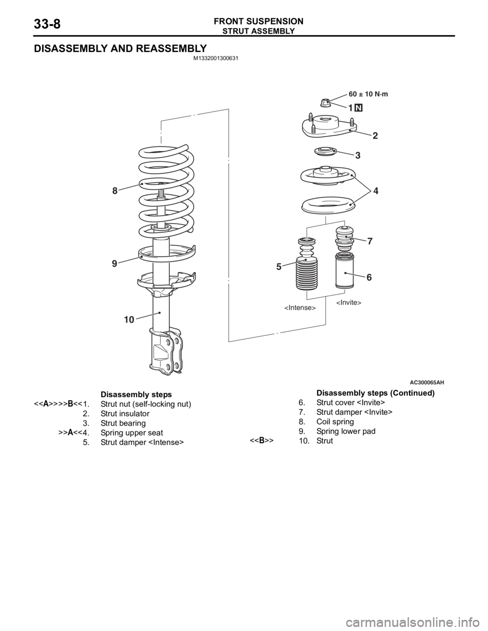
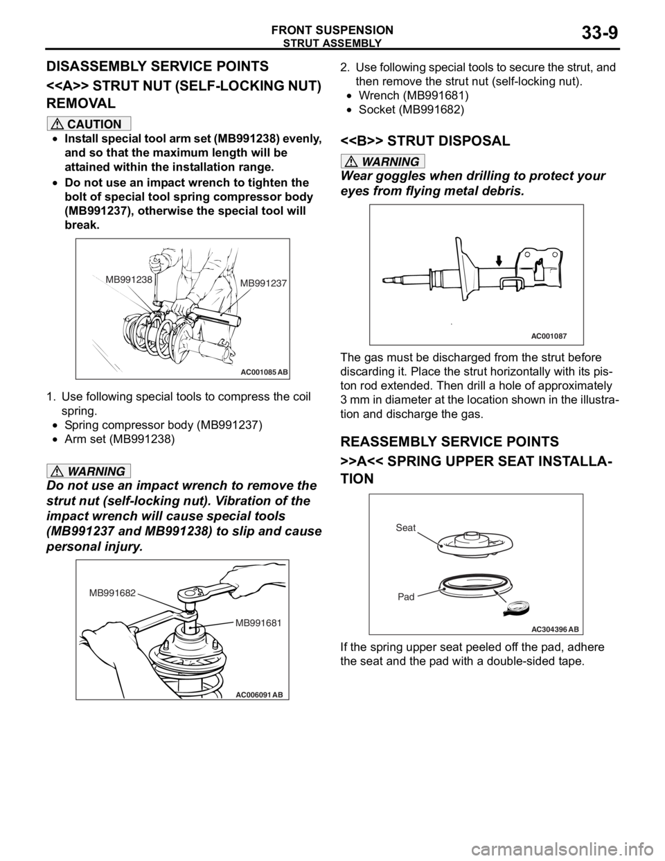
DISASSEMBLY AND REASSEMBLY
M1332001300631
AC300065
60 ± 10 N·m
2
1
N
AH
3
4
5
6
7
8
9
10
Disassembly steps
<>>>B<<1.Strut nut (self-locking nut)
2.Strut insulator
3.Strut bearing
>>A<<4.Spring upper seat
5.Strut damper
6.Strut cover
7.Strut damper
8.Coil spring
9.Spring lower pad
<>10.Str ut
Disassembly steps (Continued)
Page 191 of 800
Page 192 of 800
STRUT ASSEMBLY
FRONT SUSPENSION33-10
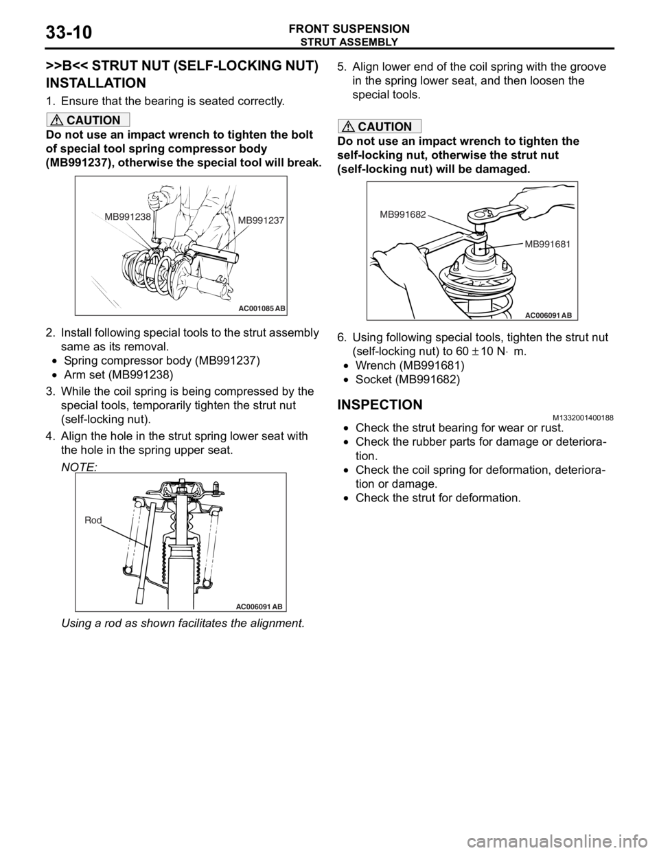
>>B<< STRUT NUT (SELF-LOCKING NUT)
INSTALLATION
1. Ensure that the bearing is seated correctly.
CAUTION
Do not use an impact wrench to tighten the bolt
of special tool spring compressor body
(MB991237), otherwise the special tool will break.
AC001085 AB
MB991238MB991237
2. Install following special tools to the strut assembly
same as its removal.
•Spring compressor body (MB991237)
•Arm set (MB991238)
3. While the coil spring is being compressed by the
special tools, temporarily tighten the strut nut
(self-locking nut).
4. Align the hole in the strut spring lower seat with the hole in the spring upper seat.
NOTE:
AC006091 AB
Rod
Using a rod as shown fa cilitates the alignment.
5. Align lower end of the coil spring with the groove
in the spring lower seat, and then loosen the
special tools.
CAUTION
Do not use an impact wrench to tighten the
self-locking nut, otherwise the strut nut
(self-locking nut) will be damaged.
AC006091 AB
MB991681
MB991682
6. Using following special tools, tighten the strut nut
(self-locking nut) to 60
± 10 N⋅m.
•Wrench (MB991681)
•Socket (MB991682)
INSPECTIONM1332001400188
•Check the strut bearing for wear or rust.
•Check the rubber parts for damage or deteriora-
tion.
•Check the coil spring for deformation, deteriora-
tion or damage.
•Check the strut for deformation.
Page 213 of 800
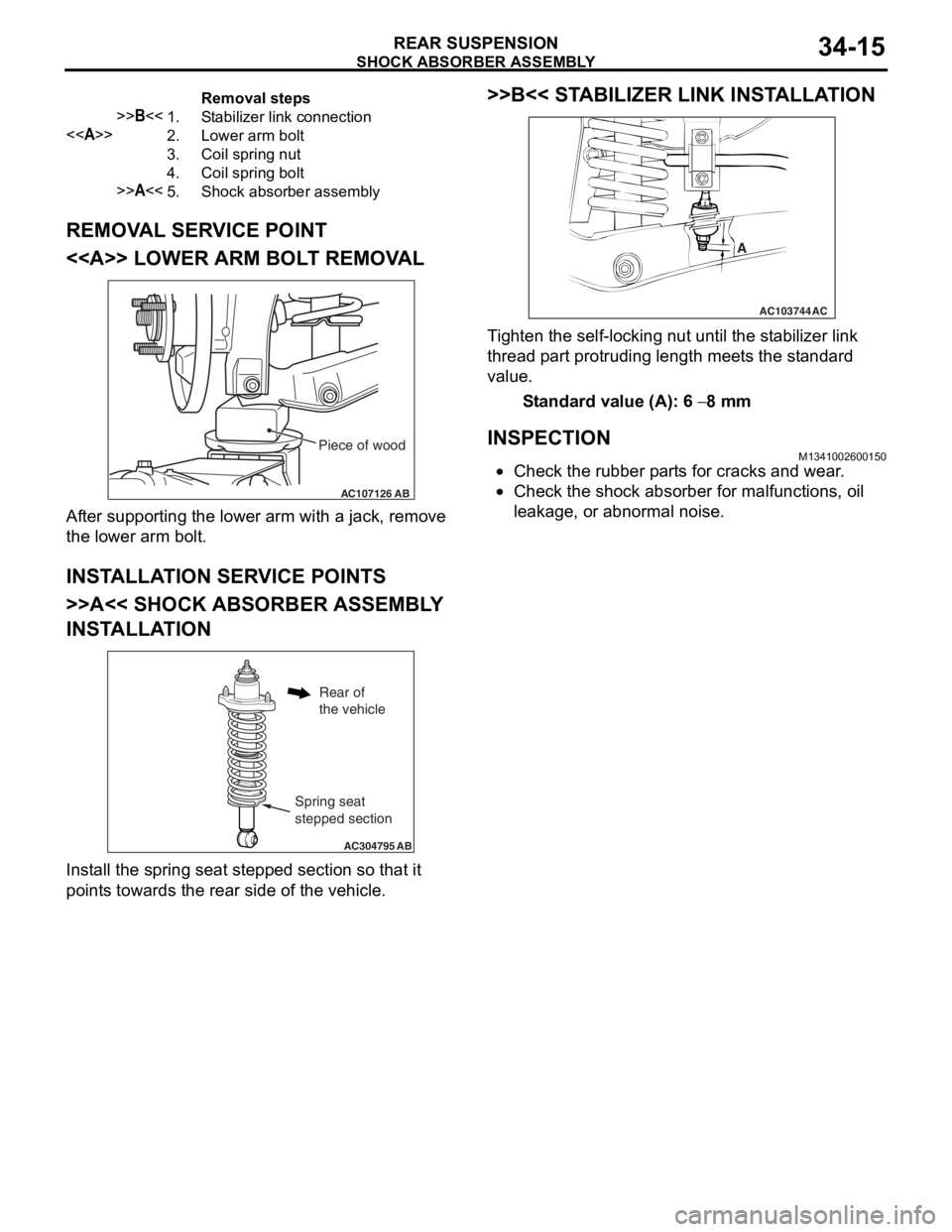
Removal steps
>>B<<1.Stabilizer link connection
<>2.Lower arm bolt
3.Coil spring nut
4.Coil spring bolt
>>A<<5.Shock absorber assembly
SHOCK ABSORBER ASSEMBLY
REAR SUSPENSION34-15
REMOVAL SERVICE POINT
<> LOWER ARM BOLT REMOVAL
AC107126AB
Piece of wood
After suppo rting the lo we r arm with a jack, remove
the lo
we r arm b o lt.
INSTALLA T ION SER VICE POINT S
>>A<< SHOCK ABSORBER ASSEMBL Y
INST
ALLA TION
AC304795 AB
Spring seat
stepped section
Rear of
the vehicle
Install the sprin g se at ste pped section so th at it
point
s towards the rea r side of th e ve hicle.
>>B<< STABILIZER LINK INST ALLA TION
AC103744
A
AC
Ti ghten the self-locking nut un til t he st ab ilizer link
thread
p a rt protrud i ng length mee t s the st a ndard
value.
St andard va lue (A): 6 − 8 mm
INSPECTIONM13410026 0015 0
•Check the rubbe r p a rt s for cracks a nd wear .
•Check the sho c k abso r ber for malfunct i ons, oil
le
akag e, or a bnormal no ise .
Page 215 of 800
SHOCK ABSORBER ASSEMBLY
REAR SUSPENSION34-17
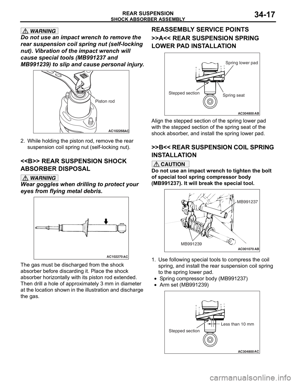
WARNING
Do not use an impact wrench to remove the
rear suspension coil spring nut (self-locking
nut). Vibration of the impact wrench will
cause special t ools (MB991237 and
MB991239) to slip and cause personal injury.
AC102268AC
Piston rod
2. While holding the piston rod, remove the rear
suspension coil spring nut (self-locking nut).
<> REAR SUSPENSION SHOCK
ABSORBER DISPOSAL
WARNING
Wear goggles when dril ling to protect your
eyes from flying metal debris.
AC102270
AC
The gas must be discharged from the shock
absorber before discarding it. Place the shock
absorber horizontally with its piston rod extended.
Then drill a hole of approximately 3 mm in diameter
at the location shown in the illustration and discharge
the gas.
REASSEMBLY SERVICE POINTS
>>A<< REAR SUSPENSION SPRING
LOWER PAD INSTALLATION
AC304800AB
Spring lower pad
Stepped section
Spring seat
Align the stepped section of the spring lower pad
with the stepped section of the spring seat of the
shock absorber, and install the spring lower pad.
>>B<< REAR SUSPENSION COIL SPRING
INSTALLATION
CAUTION
Do not use an impact wrench to tighten the bolt
of special tool spring compressor body
(MB991237). It will break the special tool.
AC001070
MB991237
MB991239
AB
1. Use following special tools to compress the coil spring, and install the rear suspension coil spring
to the spring lower pad.
•Spring compressor body (MB991237)
•
AC304800AC
Less than 10 mm
Stepped section
Arm set (MB991239)
Page 224 of 800
AC212035AC
Spring balance
Approximately
40 mm Pull
ON-V
EHICLE SER VICE
PA R K ING B RAKES36-4
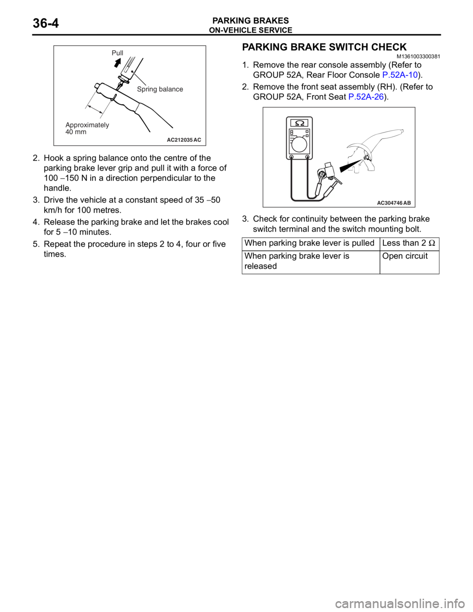
2.Hook a spring bala n ce onto th e ce ntre of the
p a rking brake lever grip and p u ll it with a force of
10 0
− 150 N in a directio n perpe ndicula r to the
ha
ndle .
3. Drive the veh i cle at a const ant speed o f 35 − 50
km/h
for 100
metre
s
.
4. Release the p a rking brake an d let th e bra k es cool
fo r 5
− 10 minutes.
5.Repe at the proce dure in ste p s 2 to 4, four or five
times.
PARKING BRAKE SW ITCH CHECK
M13610033 0038 1
1.Remove the rea r con s ole assembly (Re f er to
GROUP 52A, Rea r Floo r Co nsole
P.52A-10).
2.Remove the fro n t se at assembly (RH). (Re f er to
GROUP 52A, Fr ont Seat
P.5 2 A - 26).
AC304746AB
3.Check f o r co ntinu i ty between t he p a rking bra k e
switch terminal and th e swit ch mounting bo lt.
When parking brake lever is pulledLess than 2 Ω
When parking brake lever is
releasedOpen circuit
Page 226 of 800
PARKING BRAKE CABLE
PARKING BRAKES36-6
PARKING BRAKE CABLE
REMOVAL AND INSTALLATIONM1361001900785
Pre-removal Operation
•Rear Console Assembly and Rear Console Bracket
Removal (Refer to GROUP 52A, Rear Floor Console
P.52A-10).
•Rear Seat Cushion Assembly Removal (Refer to GROUP
52A, Rear Seat
P.52A-30).
Post-installation Operation
•Parking Brake Lever Stroke Adjustment (Refer to P.36-3).
•Rear Seat Cushion Assembly Installation (Refer to
GROUP 52A, Rear Seat P.52A-30).
•Rear Console Bracket and Rear Console Assembly
Installation (Refer to GROUP 52A, Rear Floor Console
P.52A-10).
AC301226
1
AB
2
3
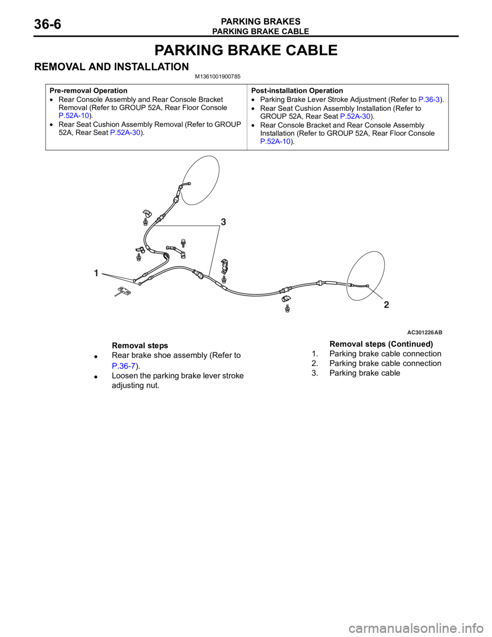
Removal steps
•Rear brake shoe assembly (Refer to
P.36-7).
•Loosen the parking brake lever stroke
adjusting nut.
1.Parking brake cable connection
2.Parking brake cable connection
3.Parking brake cable
Removal steps (Continued)