valve cover MITSUBISHI LANCER 2006 Workshop Manual
[x] Cancel search | Manufacturer: MITSUBISHI, Model Year: 2006, Model line: LANCER, Model: MITSUBISHI LANCER 2006Pages: 800, PDF Size: 45.03 MB
Page 55 of 800
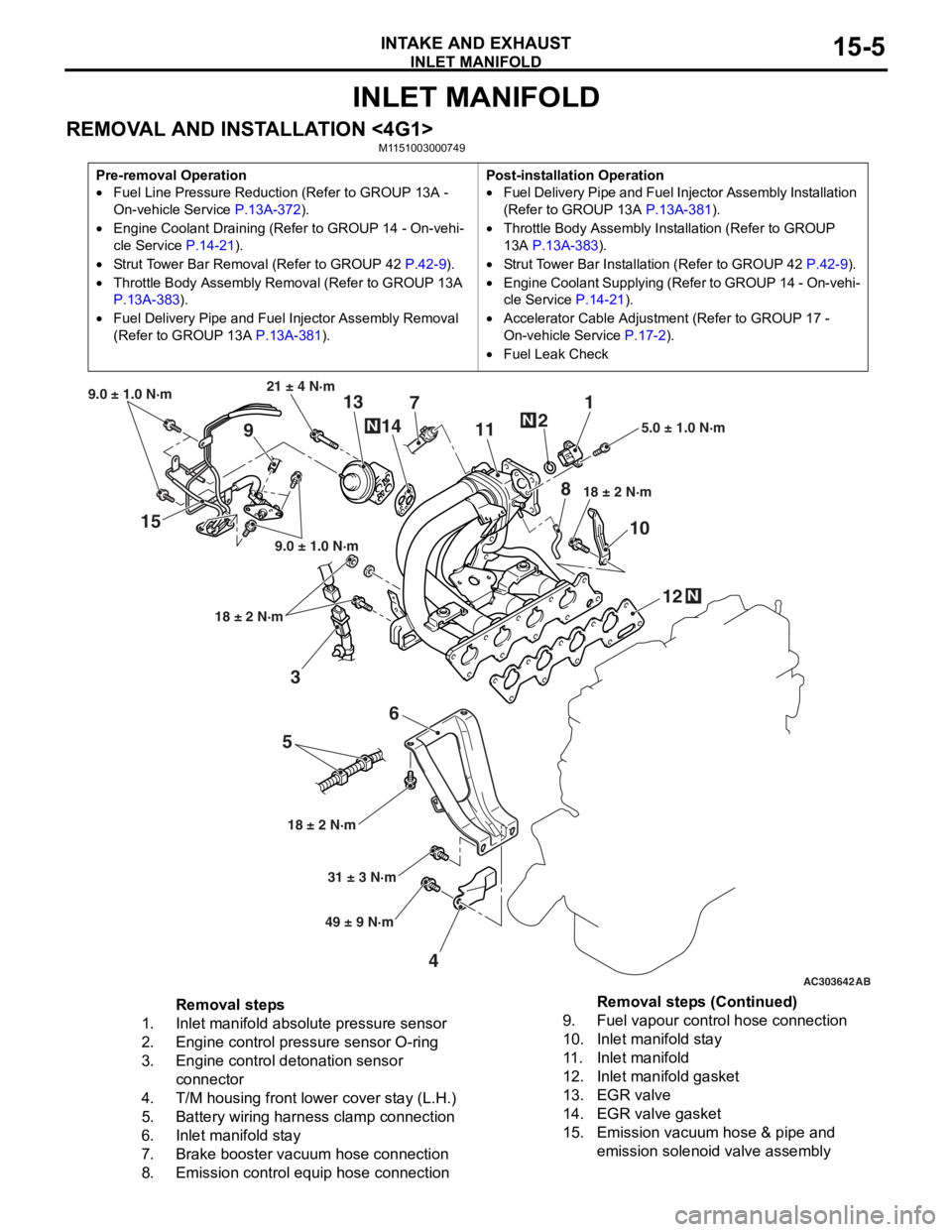
INLET MANIFOLD
INTAKE AND EXHAUST15-5
INLET MANIFOLD
REMOVAL AND INSTALLATION <4G1>M1151003000749
Pre-removal Operation
•Fuel Line Pressure Reduction (Refer to GROUP 13A -
On-vehicle Service
P.13A-372).
•Engine Coolant Draining (Refer to GROUP 14 - On-vehi-
cle Service P.14-21).
•Strut Tower Bar Removal (Refer to GROUP 42 P.42-9).
•Throttle Body Assembly Re moval (Refer to GROUP 13A
P.13A-383).
•Fuel Delivery Pipe and Fuel Injector Assembly Removal
(Refer to GROUP 13A
P.13A-381).
Post-installation Operation
•Fuel Delivery Pipe and Fuel Injector Assembly Installation
(Refer to GROUP 13A
P.13A-381).
•Throttle Body Assembly Inst allation (Refer to GROUP
13A
P.13A-383).
•Strut Tower Bar Installati on (Refer to GROUP 42 P.42-9).
•Engine Coolant Supplying (Refer to GROUP 14 - On-vehi-
cle Service P.14-21).
•Accelerator Cable Adjustment (Refer to GROUP 17 -
On-vehicle Service
P.17-2).
•Fuel Leak Check
AC303642AB
15
36
5
4 12
10
7
1
2
11
9 13
14
21 ± 4 N·m
9.0 ± 1.0 N·m
9.0 ± 1.0 N·m
18 ± 2 N·m
18 ± 2 N·m 18 ± 2 N·m
5.0 ± 1.0 N·m
31 ± 3 N·m
49 ± 9 N·m
N
N
N
8
Removal steps
1.Inlet manifold absolute pressure sensor
2.Engine control pressure sensor O-ring
3.Engine control detonation sensor
connector
4.T/M housing front lower cover stay (L.H.)
5.Battery wiring harness clamp connection
6.Inlet manifold stay
7.Brake booster vacuum hose connection
8.Emission control equip hose connection
9.Fuel vapour control hose connection
10.Inlet manifold stay
11 .Inlet manifold
12.Inlet manifold gasket
13.EGR valve
14.EGR valve gasket
15.Emission vacuum hose & pipe and
emission solenoid valve assembly
Removal steps (Continued)
Page 104 of 800
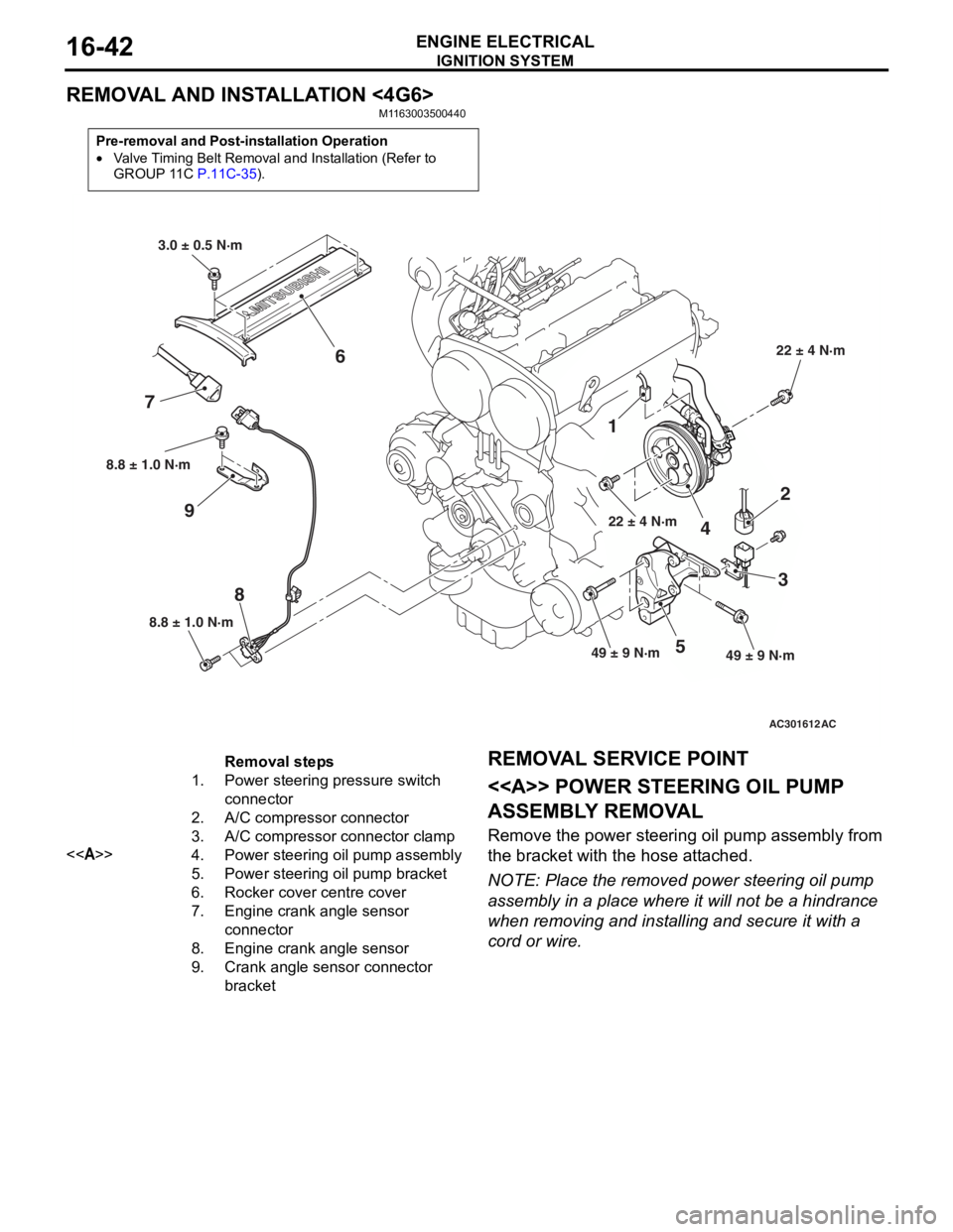
IGNITION SYSTEM
ENGINE ELECTRICAL16-42
REMOVAL AND INSTALLATION <4G6>
M1163003500440
Pre-removal and Post-installation Operation
•Valve Timing Belt Removal and Installation (Refer to
GROUP 11C P.11C-35).
AC301612
8.8 ± 1.0 N·m
8
8.8 ± 1.0 N·m
9
1
22 ± 4 N·m
4
2
3
49 ± 9 N·m49 ± 9 N·m5
22 ± 4 N·m
3.0 ± 0.5 N·m
6
7
AC
Removal steps
1.Power steering pressure switch
connector
2.A/C compressor connector
3.A/C compressor connector clamp
<>4.Power steering oil pump assembly
5.Power steering oil pump bracket
6.Rocker cover centre cover
7.Engine crank angle sensor
connector
8.Engine crank angle sensor
9.Crank angle sensor connector
bracket
REMOV A L SER VICE POINT
<> POWE R STEERING OIL PUMP
ASSEMBL
Y REMOV A L
Remove the p o wer st eering oil pump assembly from
the bra
cke t with th e hose att a ched.
NOTE: Place the remo ved power st eering oil pump
assembly in a place where it will not be a hindrance
wh
en removing an d inst a lling an d secure it with a
cord or wire.
Page 115 of 800
EMISSION CONTROL
ENGINE AND EMISSION CONTROL17-9
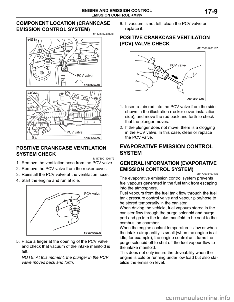
COMPONENT LOCATION (CRANKCASE
EMISSION CONTROL SYSTEM)
M1173007400208
AK300767
<4G1>
AB
PCV valve
AK204366
<4G6>
AC
PCV valve
POSITIVE CRANKCASE VENTILATION
SYSTEM CHECK
M11 7300 1 1 0017 9
1.Remove the ventilatio n hose from the PCV valve.
2.Remove the PCV valve from t he rocker cove r .
3.Reinst all the PCV valve at the ven t ila tion h o se.
4.S t art the engin e and run at idle .
AKX00336
PCV valve
AD
5.Pla c e a fing er at the open ing o f the PCV va lve
an d ch eck that vacu um o f the int a ke manifold is
fe lt.
NOTE: At this mo men t, the p l unge r in t he PCV
valve mo ves back an d forth.
6.If vacuum is not felt, clean t he PCV valve o r
re place it.
POSITIVE CRANKCASE VENTILA TION
(
P CV) V A L VE CHECK
M1173 0012 0018 7
AK100010
PCV valve
AC
1.In sert a thin rod in to the PCV valve from the side
shown in the illu strat i on (ro cke r cover in st allation
side) , and move the ro d back an d forth to ch eck
th at the plung er mo ves.
2.If the plunger does not move , there is a clo ggin g
in the PCV valve. In th is case, clean o r repla c e
th e PCV valve.
EVAPORA T IVE EMISSION CONTROL
SYSTEM
GENERAL INFORMA T ION (EV A PORA TIVE
EMISSION CONTROL SYSTEM)
M1173 0051 0040 5
The evaporat ive emission contro l syste m pre v ent s
f
uel vapours generat ed in t he fuel t ank from escaping
into t
he atmosp here.
Fuel vapours fro m the fuel t a n k flow throug h the f uel
t
a n k pre ssu re co ntrol valve an d vap our pipe/ho se to
be st
ored te mpora r ily in t he ca nister .
When dr iving the veh i cle, fue l va pours stor ed in the
canister
flow thro ugh th e purge solenoid and purge
port an
d go into the int a ke ma nifold to b e sen t to th e
combust
i on chamber .
When the eng ine co ola n t te mp eratu r e is low o r when
the int
a ke air q uantity is small (wh en the engine is at
idle
, for example), t he eng ine contro l unit turns the
purge sole
noid of f to shu t of f the fue l va pour flow to
the in
t a ke manif o ld.
This does not on ly insure the driveability when t he
engin
e is cold or runn ing und er low load b u t also st a
-
bilize the emissio n level.
Page 237 of 800

LUBRICANTS
POWER STEERING37-7
LUBRICANTS
M1372000400350
ItemSpecified lubricantQuantity
Power steering fluidATF DEXRON III or DEXRON IIApproximately 1.0 L
Steering gearBearingATF DEXRON III or DEXRON IIAs required
O-ring and seal ring
Oil seal
Special tool (MB991212,
MB991213)
Pinion and valve assembly
seal ring part
BellowsSilicon greaseAs required
Tie rod end ball jointMultipurpose grease SAE J310,
NLGI No.2 or equivalentAs required
Oil pumpFriction surface of rotor vane,
cam ring and pump coverATF DEXRON III or DEXRON IIAs required
O-ring
SEALANTS
M1372000500357
ItemSpecified sealant
Steering shaft cover assembly bolt hole on the toeboard3M ATD Part No.8513 or equivalent
Steering gearEnd plug3M ATD Part No.8661 or equivalent
Rack support cover
Page 245 of 800
ON-VEHICLE SERVICE
POWER STEERING37-15
6. Check whether or not the hydraulic pressure is the standard value when no-load conditions are
created by fully opening the shut-off valve of the
pressure gauge.
Standard value: 0.2 − 0.7 MPa
7. If it is not within the standard value, the probable cause is a malfunction of the oil line or steering
gear, so check these parts and repair as
necessary.
8. Turn the steering wheel all the way to the left or right; then check whether or not the retention
hydraulic pressure is the standard value.
Standard value: 8.8 − 9.5 MPa
9. If not the standard value, overhaul the steering gear. Remeasure fluid pressure.
10. Remove the special tools, and then tighten the
pressure hose to the specified torque.
Tightening torque: 57 ± 7 N⋅m
11. Bleed the system (Refer to P.37-14).
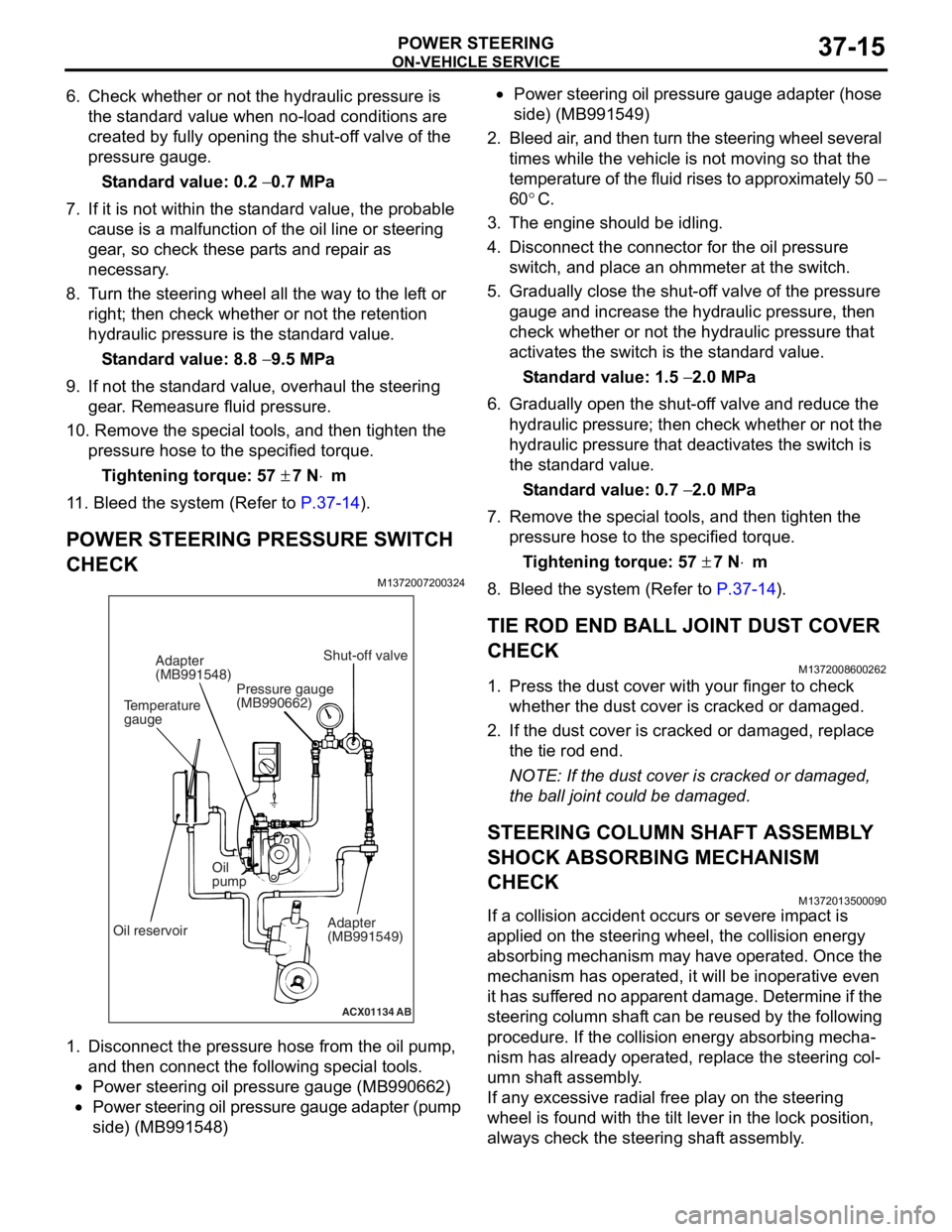
POWER STEERING PRESSURE SWITCH
CHECK
M1372007200324
ACX01134 AB
Temperature
gaugeAdapter
(MB991548)
Oil reservoir Oil
pump
Adapter
(MB991549)
Shut-off valve
Pressure gauge
(MB990662)
1. Disco nnect the pre s sure hose from the oil pump ,
an d then con nect the followin g sp ecial too l s.
•Power steering oil pressure gauge (MB990 662)
•Power steering oil pressure gauge ad apter (pump
side) (MB99154
8)
•Power steering oil pressure gaug e a dapte r (ho s e
side) (MB99154
9)
2. Bleed air , and the n turn t he steering wheel several
times while the vehicle is not moving so that the
tempe r atu r e o f th e flu i d rise s to approximately 50
−
60
°C.
3. Th e engine should be idling.
4.Disco nnect the conne ctor fo r the o il pr essure
switch , and p l ace an o h mmeter a t the switch .
5.Gradua lly close the shut-of f valve of the pressure
g auge a nd in crease the hyd r aulic pre ssu re, the n
check wheth e r or no t the h y drau lic pressure that
a c tivates the switch is the st a ndard valu e.
St andard va lue: 1.5 − 2.0 MPa
6.Gradua lly open the shut-of f va lve and re duce the
h y drau lic p r essure; then check whethe r o r n o t the
h y drau lic pressure that de activate s the switch is
th e st and ard va lue.
St andard va lue: 0.7 − 2.0 MPa
7.Remove the special tools, and then tighten the
p r essure hose to the specified torque .
Ti ghte n ing torque: 57 ± 7 N⋅m
8.Bleed the system (Refer to P.37-14).
TIE ROD END BALL JOINT DUST COVER
CHECK
M13720086 0026 2
1.Press th e dust co ver wit h you r fing er to check
whet her the dust cover is cra cke d or da mage d.
2.If the du st cover is cracked o r damaged, repla c e
th e tie rod end .
NOTE: If the dust cover is cra cke d or da mag ed,
th
e ball jo int could be da mage d.
STEERING COLUMN SHAFT ASSEMBL Y
SHOCK ABSORBING MECHANISM
CHECK
M13720135 0009 0
If a collision accid ent occu rs or seve re imp a ct is
applied on
the steering w heel, the collision energy
abso
r bing mechanism ma y h a ve opera t ed. Once the
mechanism
has o perate d , it will b e ino perative e v en
it has
suf f er ed no app a r en t d a mage . De termin e if the
steering colu
mn shaf t can b e reused b y th e following
proce
dure. If the collision en ergy a b sor b ing mecha
-
nism has already operated, rep l ace the steering col-
umn shaft assembly .
If any excessive radial fre e pla y on the steering
wh
eel is fo und with the tilt lever in the lock po sit i on,
always ch
eck the steering shaf t assembly .
Page 256 of 800
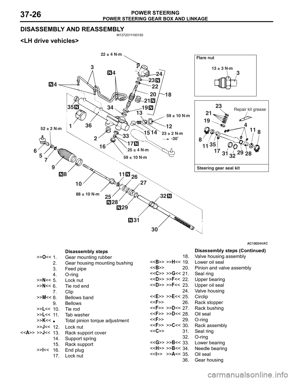
POWER STEERING GEAR BOX AND LINKAGE
POWER STEERING37-26
DISASSEMBLY AND REASSEMBLY
M1372011100193
AC100244AC
3
13 ± 3 N·m
Steering gear seal kit
Flare nut
Repair kit grease
23
21
19 4
11 8
28
29
32
31
17
35
11
8
22 ± 4 N·m
59 ± 10 N·m
23 ± 2 N·m
-30
12
14
15
33
17
59 ± 10 N·m 25 ± 4 N·m
18
24
23
20
19
21
22
13
34 4
4
3
1 36
216
30
31
32
27
29
28
25 26
1188 ± 10 N·m
10
8
9
7
5
6
52 ± 2 N·m
35
Disassembly steps
>>O<<1.Gear mounting rubber
2.Gear housing mounting bushing
3.Feed pipe
4.O-ring
>>N<<5.Lock nut
>>N<<6.Tie rod end
7.Clip
>>M<<8.Bellows band
9.Bellows
>>L<<10.Tie rod
>>L<<11 .Tab washer
>>K<<•Total pinion torque adjustment
>>J<<12.Lock nut
<>>>J<<13.Rack support cover
14.Support spring
15.Rack support
>>I<<16.End plug
17.Lock nut
18.Valve housing assembly
<>>>H<<19.Lower oil seal
<>20.Pinion and valve assembly
<
<
<
24.Valve housing
<
<
<
<
<
<
<
32.O-ring
<
<
<>>>A<<35.Oil seal
36.Gear housing
Disassembly steps (Continued)
Page 257 of 800
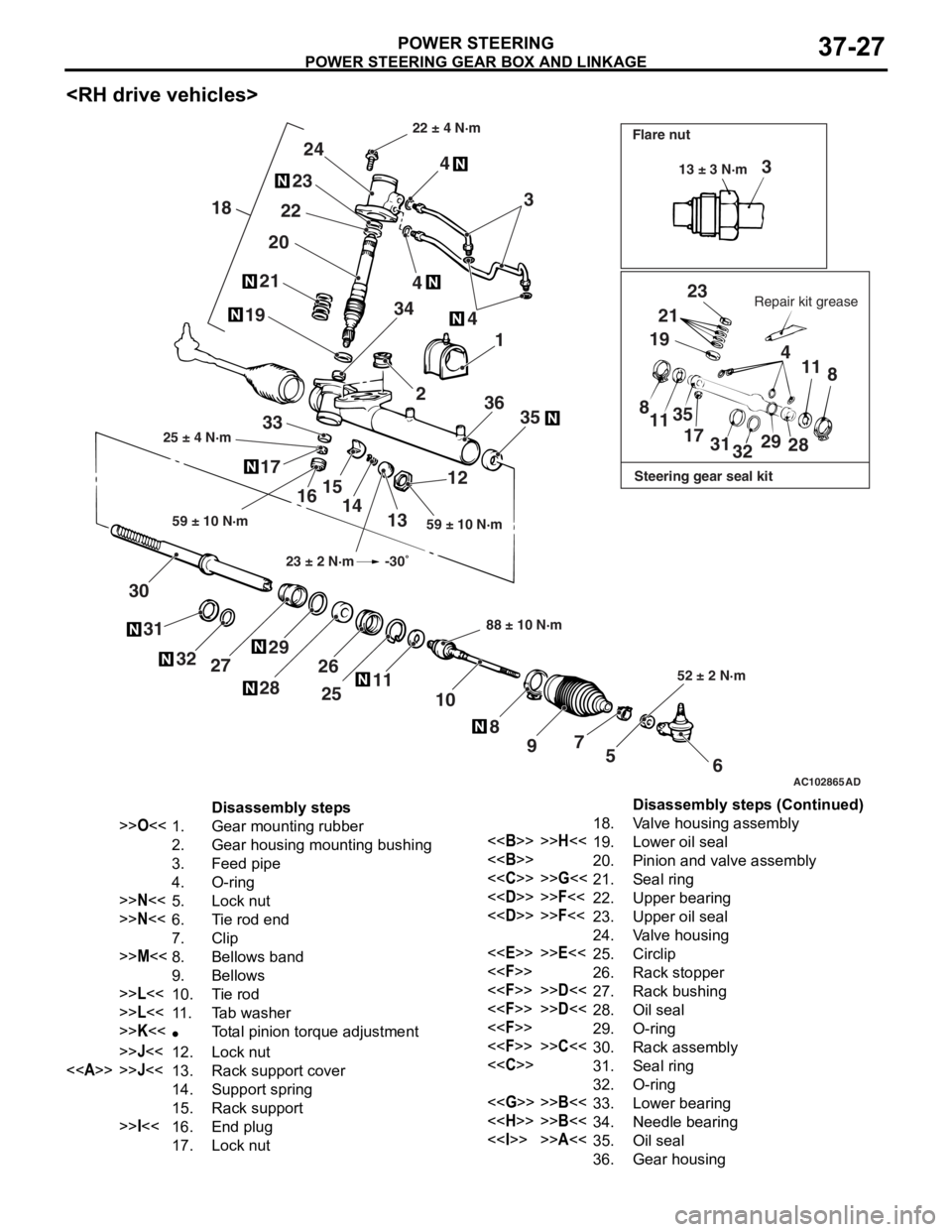
POWER STEERING GEAR BOX AND LINKAGE
POWER STEERING37-27
AC102865
3
23
21
19 4
11 8
8 11 35
17 3132 29
28
6
5
7
9
8
10
11
25
26
28 29
27
32
31
30 12
13
14
15
16
17 33
35
36 1
4
2
34
4 4
3
24
23
22
21 20
19
18
AD
Steering gear seal kit
Flare nut
Repair kit grease
22 ± 4 N·m
59 ± 10 N·m
25 ± 4 N·m
88 ± 10 N·m52 ± 2 N·m
59 ± 10 N·m 13 ± 3 N·m
23 ± 2 N·m -30
Disassembly steps
>>O<<1.Gear mounting rubber
2.Gear housing mounting bushing
3.Feed pipe
4.O-ring
>>N<<5.Lock nut
>>N<<6.Tie rod end
7.Clip
>>M<<8.Bellows band
9.Bellows
>>L<<10.Tie rod
>>L<<11 .Tab washer
>>K<<•Total pinion torque adjustment
>>J<<12.Lock nut
<>>>J<<13.Rack support cover
14.Support spring
15.Rack support
>>I<<16.End plug
17.Lock nut
18.Valve housing assembly
<>>>H<<19.Lower oil seal
<>20.Pinion and valve assembly
<
<
<
24.Valve housing
<
<
<
<
<
<
<
32.O-ring
<
<
<>>>A<<35.Oil seal
36.Gear housing
Disassembly steps (Continued)
Page 259 of 800
Page 261 of 800
POWER STEERING GEAR BOX AND LINKAGE
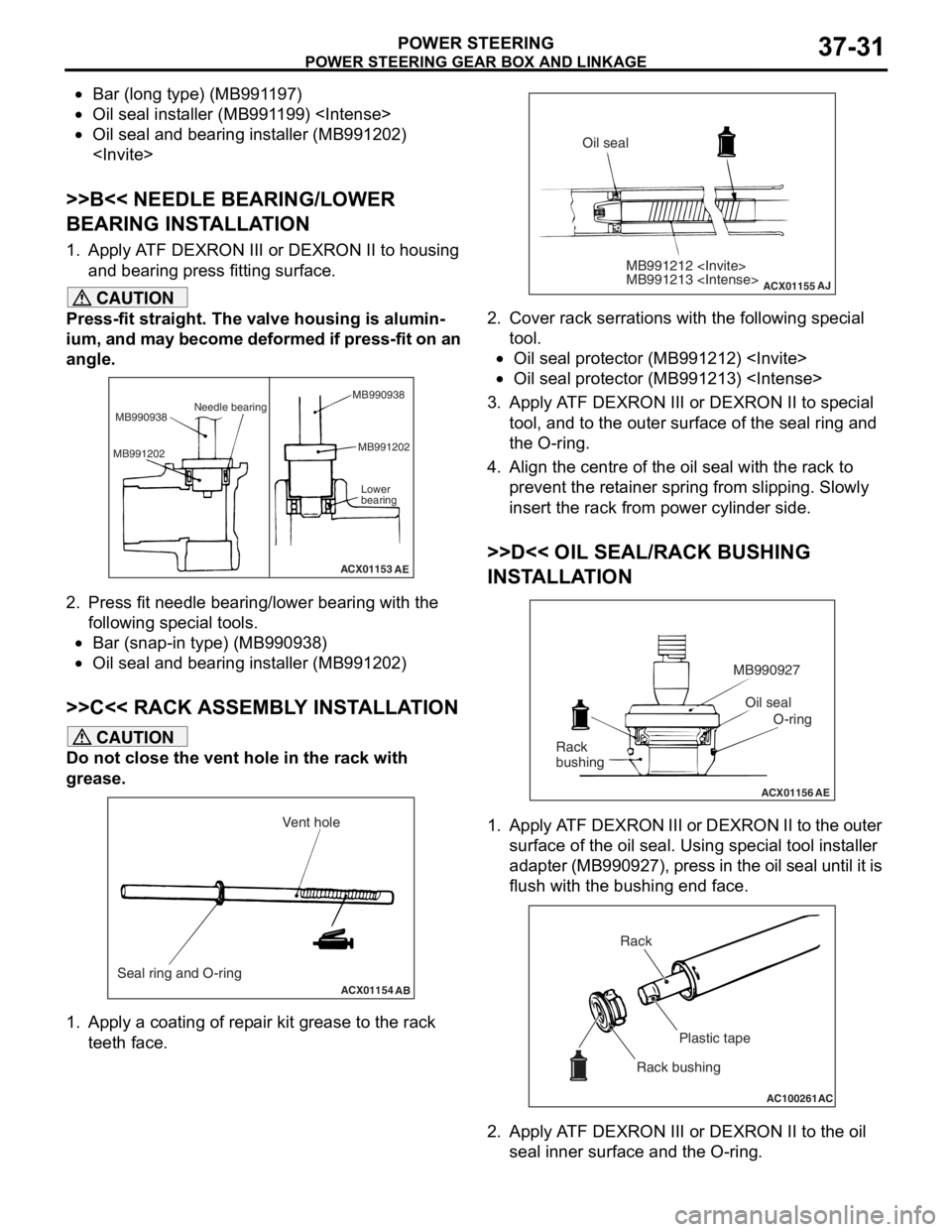
POWER STEERING37-31
•Bar (long type) (MB991197)
•Oil seal installer (MB991199)
•Oil seal and bearing installer (MB991202)
>>B<< NEEDLE BEARING/LOWER
BEARING INSTALLATION
1. Apply ATF DEXRON III or DEXRON II to housing and bearing press fitting surface.
CAUTION
Press-fit straight. The valve housing is alumin-
ium, and may become deformed if press-fit on an
angle.
ACX01153
Needle bearing
MB990938
MB991202 MB991202
Lower
bearing
AE
MB990938
2. Press fit needle bearing/lower bearing with the
following special tools.
•Bar (snap-in type) (MB990938)
•Oil seal and bearing installer (MB991202)
>>C<< RACK ASSEMBLY INSTALLATION
CAUTION
Do not close the vent hole in the rack with
grease.
ACX01154 AB
Seal ring and O-ring Vent hole
1. Apply a coating of repair kit grease to the rack
teeth face.
ACX01155
MB991212
MB991213
AJ
Oil seal
2. Cover rack serrations with the following special tool.
•Oil seal protector (MB991212)
•Oil seal protector (MB991213)
3. Apply ATF DEXRON III or DEXRON II to special
tool, and to the outer surface of the seal ring and
the O-ring.
4. Align the centre of the oil seal with the rack to prevent the retainer spring from slipping. Slowly
insert the rack from power cylinder side.
>>D<< OIL SEAL/RACK BUSHING
INSTALLATION
ACX01156 AE
Oil seal
O-ring
MB990927
Rack
bushing
1. Apply ATF DEXRON III or DEXRON II to the outer surface of the oil seal. Using special tool installer
adapter (MB990927), press in the oil seal until it is
flush with the bushing end face.
AC100261 AC
Rack
Plastic tape
Rack bushing
2. Apply ATF DEXRON III or DEXRON II to the oil seal inner surface and the O-ring.
Page 269 of 800
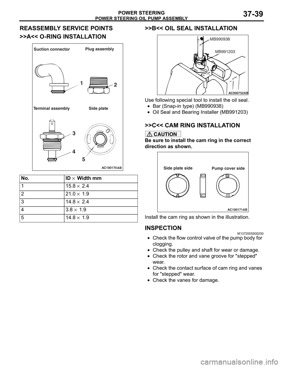
POWER STEERING OIL PUMP ASSEMBLY
POWER STEERING37-39
REASSEMBLY SERVICE POINTS
>>A<< O-RING INSTALLATION
AC100170AB
Suction connector Plug assembly
Terminal assembly Side plate
1 2
3
4 5
No.ID × Width mm
115.8 × 2.4
221.0 × 1.9
314.8 × 2.4
43.8 × 1.9
514.8 × 1.9
>>B<< OIL SEAL INST ALLA TION
AC000752
MB990938
AB
MB991203
Use following spe c ia l too l to inst all the oil seal.
•Bar (Snap-in type) (MB9909 38)
•Oil Seal and Bearin g Inst aller (MB9912 03)
>>C<< CAM RING INSTALLA TION
CAUTION
Be sure to install the cam ring in the correct
direction as shown.
AC100171AB
Side plate side
Pump cover side
Install the cam ring as shown in the illustration.
INSPECTION
M1372005500200
•Check the flow control valve of the pump body for
clogging.
•Check the pulley and shaft for wear or damage.
•Check the rotor and vane groove for "stepped"
wear.
•Check the contact surface of cam ring and vanes
for "stepped" wear.
•Check the vanes for damage.