warning light MITSUBISHI LANCER 2006 Workshop Manual
[x] Cancel search | Manufacturer: MITSUBISHI, Model Year: 2006, Model line: LANCER, Model: MITSUBISHI LANCER 2006Pages: 800, PDF Size: 45.03 MB
Page 64 of 800
CHARGING SYSTEM
ENGINE ELECTRICAL16-2
CHARGING SYSTEM
GENERAL INFORMATIONM1161000100522
The charging system uses the alternator output to
keep the battery charged at a constant level under
various electrical loads.
OPERATION
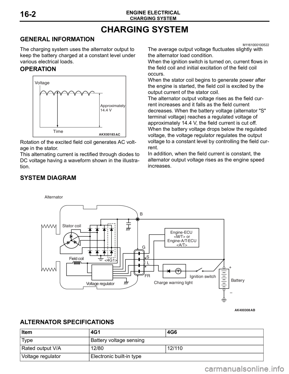
AKX00183
VoltageTime
Approximately
14.4 V
AC
Rota tion of the excited fi eld coil gene rates AC volt-
age in the sta t or .
This alternatin g cur r ent is rectified throu gh diodes to
DC volt
age h a ving a waveform sh own in t he illustra
-
tion.
The average outpu t volt a ge flu c tua t es slightly with
the alternato
r load con d ition.
When the ign i tion switch is t u rned on, current flows in
the field coil and initial e
x cit a tion of the field coil
occurs.
When the st ator coil beg ins to gen erate p o wer af ter
the eng
ine is st a r ted, th e fie l d coil is excited by th e
output
curren t of th e st ator coil.
The alternator outpu t volt a ge rises as th e fie l d cur-
rent increa ses and it falls a s the field cu rrent
decre
ases. Whe n the b a ttery volt a ge (alternato r "S"
terminal volt
ag e) reaches a regulated volt ag e of
approximately 14.4
V , the field current is cut o f f.
When th
e batte ry volt age drop s be low the regulated
volt
ag e, the volt ag e regulator re gulat es th e outp u t
volt
ag e to a const ant level by contro lling the field cur
-
rent.
In addition, when th e fie l d current is const a n t, the
altern
ator ou tput volt age rise s as the e ngine spe ed
increase
s .
SYSTEM DIAGRAM
AK400308
Alternator
B
Stator coil
Engine-ECU
Engine-A/T-ECU
G
SL
FR
<4G1>
Voltage regulator Charge warning lightIgnition switch
Battery
Field coil
+
–
AB
AL TERNA T O R SPECIFICA T IONS
Item4G14G6
Ty p eBattery voltage sensing
Rated output V/A12/8012/110
Voltage regulatorElectronic built-in type
Page 67 of 800
Page 183 of 800
33-1
GROUP 33
FRONT
SUSPENSION
CONTENTS
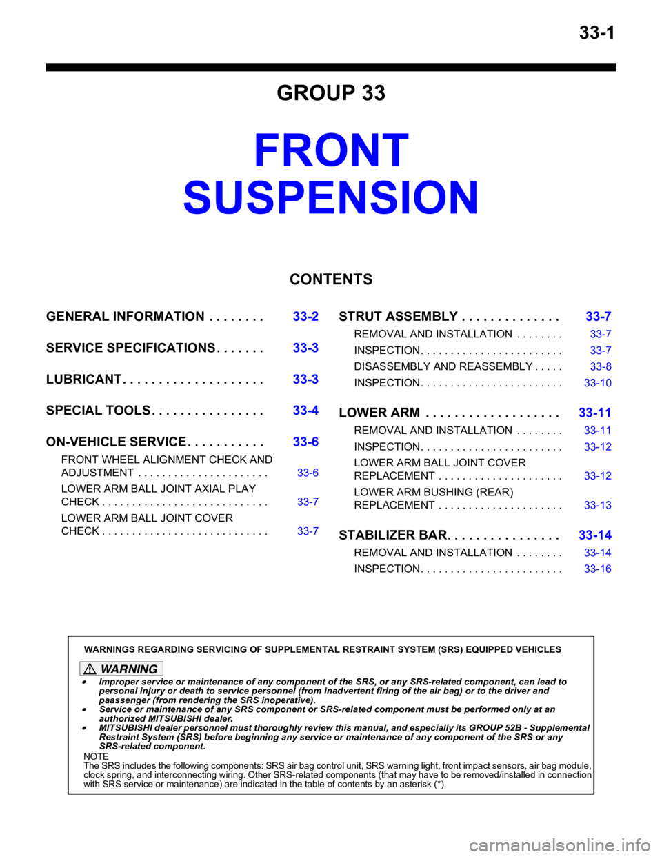
GENERAL INFORMATIO N . . . . . . . .33-2
SERVICE SPECIFICATIONS . . . . . . .33-3
LUBRICANT . . . . . . . . . . . . . . . . . . . .33-3
SPECIAL TOOLS . . . . . . . . . . . . . . . .33-4
ON-VEHICLE SERVICE . . . . . . . . . . .33-6
FRONT WHEEL ALIGNMENT CHECK AND
ADJUSTMENT . . . . . . . . . . . . . . . . . . . . . . 33-6
LOWER ARM BALL JOINT AXIAL PLAY
CHECK . . . . . . . . . . . . . . . . . . . . . . . . . . . . 33-7
LOWER ARM BALL JOINT COVER
CHECK . . . . . . . . . . . . . . . . . . . . . . . . . . . . 33-7
STRUT ASSEMBLY . . . . . . . . . . . . . .33-7
REMOVAL AND INSTALLATION . . . . . . . . 33-7
INSPECTION. . . . . . . . . . . . . . . . . . . . . . . . 33-7
DISASSEMBLY AND REASSEMBLY . . . . . 33-8
INSPECTION. . . . . . . . . . . . . . . . . . . . . . . . 33-10
LOWER ARM . . . . . . . . . . . . . . . . . . .33-11
REMOVAL AND INSTALLATION . . . . . . . . 33-11
INSPECTION. . . . . . . . . . . . . . . . . . . . . . . . 33-12
LOWER ARM BALL JOINT COVER
REPLACEMENT . . . . . . . . . . . . . . . . . . . . . 33-12
LOWER ARM BUSHING (REAR)
REPLACEMENT . . . . . . . . . . . . . . . . . . . . . 33-13
STABILIZER BAR. . . . . . . . . . . . . . . .33-14
REMOVAL AND INSTALLATION . . . . . . . . 33-14
INSPECTION. . . . . . . . . . . . . . . . . . . . . . . . 33-16
WARNINGS REGARDING SERVICING OF SUPPLEMENTAL RESTRAINT SYSTEM (SRS) EQUIPPED VEHICLES
WARNING
•Improper service or maintenance of any component of the SRS, or any SRS-related component, can lead to
personal injury or death to service personnel (from inad vertent firing of the air bag) or to the driver and
paassenger (from rendering the SRS inoperative).
•Service or maintenance of any SRS component or SRS-related component must be performed only at an
authorized MITSUBISHI dealer.
•MITSUBISHI dealer personnel must thoroughly review this manual, and especially its GROUP 52B - Supplemental
Restraint System (SRS) before beginning any service or maintenance of any component of the SRS or any
SRS-related component.
NOTE
The SRS includes the following components: SRS air bag control unit, SRS warning light, front impact sensors, air bag module,
clock spring, and interconnecting wiring. Other SRS-related components (that may have to be removed/installed in connection
with SRS service or maintenance) are indicated in the table of contents by an asterisk (*).
Page 231 of 800
37-1
GROUP 37
POWER STEERING
CONTENTS
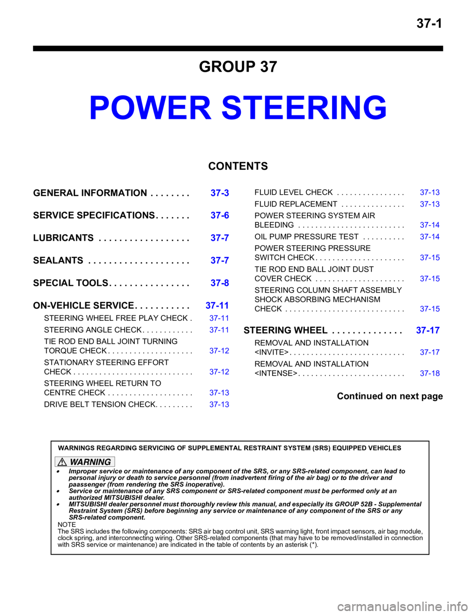
GENERAL INFORMATION . . . . . . . .37-3
SERVICE SPECIFICATIONS . . . . . . .37-6
LUBRICANTS . . . . . . . . . . . . . . . . . .37-7
SEALANTS . . . . . . . . . . . . . . . . . . . .37-7
SPECIAL TOOLS . . . . . . . . . . . . . . . .37-8
ON-VEHICLE SERVICE . . . . . . . . . . .37-11
STEERING WHEEL FREE PLAY CHECK . 37-11
STEERING ANGLE CHECK . . . . . . . . . . . . 37-11
TIE ROD END BALL JOINT TURNING
TORQUE CHECK . . . . . . . . . . . . . . . . . . . . 37-12
STATIONARY STEERING EFFORT
CHECK . . . . . . . . . . . . . . . . . . . . . . . . . . . . 37-12
STEERING WHEEL RETURN TO
CENTRE CHECK . . . . . . . . . . . . . . . . . . . . 37-13
DRIVE BELT TENSION CHECK. . . . . . . . . 37-13
FLUID LEVEL CHECK . . . . . . . . . . . . . . . . 37-13
FLUID REPLACEMENT . . . . . . . . . . . . . . . 37-13
POWER STEERING SYSTEM AIR
BLEEDING . . . . . . . . . . . . . . . . . . . . . . . . . 37-14
OIL PUMP PRESSURE TEST . . . . . . . . . . 37-14
POWER STEERING PRESSURE
SWITCH CHECK . . . . . . . . . . . . . . . . . . . . . 37-15
TIE ROD END BALL JOINT DUST
COVER CHECK . . . . . . . . . . . . . . . . . . . . . 37-15
STEERING COLUMN SHAFT ASSEMBLY
SHOCK ABSORBING MECHANISM
CHECK . . . . . . . . . . . . . . . . . . . . . . . . . . . . 37-15
STEERING WHEEL . . . . . . . . . . . . . .37-17
REMOVAL AND INSTALLATION
REMOVAL AND INSTALLATION
Continued on next page
WARNINGS REGARDING SERVICING OF SUPPLEMENTAL RESTRAINT SYSTEM (SRS) EQUIPPED VEHICLES
WARNING
•Improper service or maintenance of any component of the SRS, or any SRS-related component, can lead to
personal injury or death to service personnel (from inad vertent firing of the air bag) or to the driver and
paassenger (from renderin g the SRS inoperative).
•Service or maintenance of any SRS component or SRS-related component must be performed only at an
authorized MITSUBISHI dealer.
•MITSUBISHI dealer personnel must thoroughly review th is manual, and especially its GROUP 52B - Supplemental
Restraint System (SRS) before begi nning any service or maintenance of any component of the SRS or any
SRS-related component.
NOTE
The SRS includes the following components: SRS air bag control unit, SRS warning light, front impact sensors, air bag module,
clock spring, and interconnecting wiring. Other SRS-related components (that may have to be removed/installed in connection
with SRS service or maintenance) are indicated in the table of contents by an asterisk (*).
Page 329 of 800
ACX00571
M.U.T.-II connectedWithin 10 seconds
Hazard
warning
switch ON
OFF 1
23
45
6
AB
KEYLE SS ENTR Y SYSTEM
BOD Y42-57
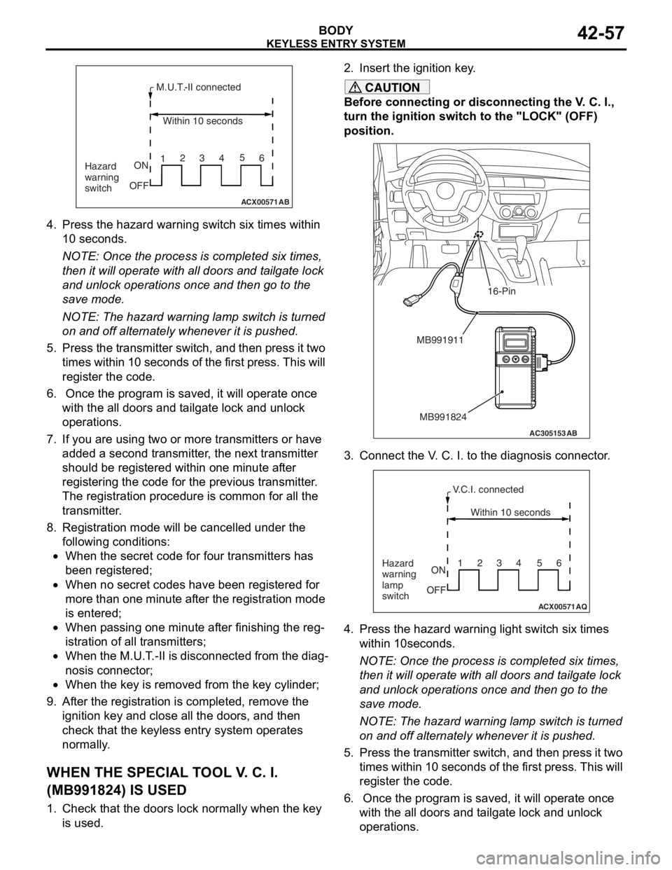
4.Press th e hazard warning switch six times within
10 seconds.
NOTE: Once th e process is comple ted six t i me s,
th
en it
will operate with al l do ors an d t a ilgate lock
an
d unlock opera t ions once and then go to th e
save
mode .
NOTE: The h a zard warnin g lamp switch is turned
on
and o ff alt e rnately when ever it is pushed.
5.Pre s s th e tr ansmitter switch, a nd then pre s s it two
t i mes within 10 second s of th e f i rst pre s s. This will
reg i st er the code.
6. Once the p r ogram is saved, it will opera t e once
wit h the a ll d oors a nd t a ilgate lock and unlo ck
op erations.
7.If you a r e using t w o or mo re transmitters or have
ad ded a second tra n smitter , the n e xt tra n smitter
should be re gistered within o ne minute af ter
reg i st ering the code fo r the pre v io us tra n smitter .
Th e registration pr oced ure is co mmo n for a ll th e
tra n smitter .
8.Registra tion mode will be ca ncelled under the
fo llowing condit i ons:
•When the secr et co de for fo ur transmitters has
bee
n registere d ;
•When no secre t cod e s h a ve b een re gist ered fo r
more tha
n one minute af ter the registration mode
is ente
r ed;
•When p a ssing o ne minute af ter fin i sh ing t he reg-
istration of all t r ansmitte rs;
•When the M.U.T . -II is d i sconne cted from th e dia g-
nosis connecto r;
•When the key is re moved fro m the key cylin der;
9.Af ter the registration is completed, remove the
ignition key a nd close all the d oors, and th en
check tha t the keyless entry syste m op erates
no rmally .
WH EN THE SPECIAL T O OL V . C. I.
(
M B991824) I S USED
1.Check t hat the doors lock n o rmally wh en the key
is used.
2. In sert t he ig nition ke y .
CAUTION
Before connecting or disconnecting the V. C. I.,
turn the ignition switch to the "LOCK" (OFF)
position.
AC305153AB
MB991911
MB991824
16-Pin
3. Connect the V. C. I. to the diagnosis connector.
ACX00571
Within 10 seconds
Hazard
warning
lamp
switch ON
OFF 1234 56
AQ
V.C.I. connected
4. Press the hazard warning
light switch six times
within 10seconds.
NOTE: Once the process is completed six times,
then it will operate with all doors and tailgate lock
and unlock operations once and then go to the
save mode.
NOTE: The hazard warning lamp switch is turned
on and off alternately whenever it is pushed.
5. Press the transmitter switch, and then press it two times within 10 seconds of the first press. This will
register the code.
6. Once the program is saved, it will operate once with the all doors and tailgate lock and unlock
operations.
Page 466 of 800
90-2
TAIL LAMP, POSITION LAMP,
LICENCE PLATE LAMP AND
LIGHTING MONITOR BUZZER
TAIL LAMP, POSITION LAMP, LICENCE
PLATE LAMP AND LIGHTING MONITOR
BUZZER
TAIL LAMP, POSITION LAMP, LICENCE
PLATE LAMP AND LIGHTING MONITOR
BUZZER
FRONT FOG LAMP
FRONT FOG LAMP
FRONT FOG LAMP
ROOM LAMP AND LUGGAGE
COMPARTMENT LAMP
ROOM LAMP AND LUGGAGE
COMPARTMENT LAMP
ROOM LAMP AND LUGGAGE
COMPARTMENT LAMP
ROOM LAMP,PERSONAL LAMP
AND LUGGAGE ROOM LAMP
ROOM LAMP, PERSONAL LAMP AND
LUGGAGE ROOM LAMP
ROOM LAMP, PERSONAL LAMP AND
LUGGAGE ROOM LAMP
REAR FOG LAMP
REAR FOG LAMP
REAR FOG LAMP
HEADLAMP LEVELLING SYSTEM
HEADLAMP LEVELLING SYSTEM
HEADLAMP LEVELLING SYSTEM
TURN-SIGNAL LAMP AND HAZARD
WARNING LAMP
TURN SIGNAL LAMP AND HAZARD
WARNING LAMP
TURN SIGNAL LAMP AND HAZARD
WARNING LAMP
BACK-UP LAMP
BACK-UP LAMP
BACK-UP LAMP
STOP LAMP
STOP LAMP
STOP LAMP
STOP LAMP
STOP LAMP
HORN . . . . . . . . . . . . . . . . . . . . . . . . .90-186
METER AND GAUGE
METER AND GAUGE
METER AND GAUGE
FUEL WARNING LAMP, OIL
PRESSURE WARNING LAMP AND
BRAKE WARNING LAMP
FUEL WARNING LAMP, OIL PRESSURE
WARNING LAMP AND BRAKE WARNING
LAMP
FUEL WARNING LAMP, OIL PRESSURE
WARNING LAMP AND BRAKE WARNING
LAMP
POWER WINDOWS
POWER WINDOWS
Continued on next page
Page 470 of 800
J/C
CIRCUIT DIAGRAMS90-6
J/C
J/C
NOTE: IN ACTUAL VEHICLES, ANY OF THE TERMINALS CONNECTED IN J/C
ARE USED. THE TERMINAL ARRANGEMENT DESCRIBED IN THE CIRCUIT
DIAGRAM MAY NOT BE IDENTICAL TO THOSE OF THE VEHICLES.
·CENTRAL DOOR
LOCKING SYSTEM
·FRONT FOG
LAMP
·HEADLAMP
·HEADLAMP
WASHER
·POWER WINDOWS
·REAR FOG LAMP
·ROOM LAMP AND
LUGGAGE
COMPARTMENT
LAMP
·ROOM LAMP
PERSONAL LAMP
AND LUGGAGE
ROOM LAMP ·TAIL LAMP,
POSITION LAMP,
LICENCE PLATE
LAMP AND
LIGHTING MONITOR
BUZZER
·TURN-SIGNAL
LAMP AND
HAZARD
WARNING LAMP
·WINDSHIELD
WIPER AND
WASHER
RELAY BOX
(FUSE )·FRONT FOG LAMP
·HEADLAMP
·HEADLAMP WASHER
·REAR FOG LAMP
·TAIL LAMP, POSITION
LAMP, LICENCE PLATE
LAMP AND LIGHTING
MONITOR BUZZER
·TURN-SIGNAL LAMP AND
HAZARD WARNING LAMP
·WINDSHIELD WIPER
AND WASHER
SPARE
CONNECTOR
(FOR AUDIO)CLOCK
·FUEL WARNING
LAMP
·INVECS-II
4A/T
·METER AND
GAUGE
RELAY BOX
(FUSE )
TURN-SIGNAL
LAMP AND
HAZARD WARNING
LAMP HEATED
SEAT
·AUTOMATIC AIR
CONDITIONER
·HEATER
·MANUAL AIR
CONDITIONER
·REAR WINDOW
DEFOGGER
AND DOOR
MIRROR HEATER CIGARETTE
LIGHTER AND
ASHTRAY
ILLUMINATION
LAMP RHEOSTAT
SPARE
CONNECTOR
(FOR AUDIO) HEADLAMP
LEVELLING
SYSTEM
·FRONT
FOG LAMP
·REAR
FOG LAMP
20
22
AUTOMATIC AIR
CONDITIONER
Page 471 of 800
J/C
CIRCUIT DIAGRAMS90-7
REAR WIPER
AND WASHER
·FRONT FOG LAMP
·HEADLAMP
·HEADLAMP WASHER
·REAR FOG LAMP
·TAIL LAMP, POSITION
LAMP, LICENCE PLATE
LAMP AND LIGHTING
MONITOR BUZZER
·WINDSHIELD WIPER
AND WASHERINVECS-II
4A/T POWER
WINDOWSSTOP
LAMP·INVECS-II
4A/T
·REAR WIPER
AND WASHER
·STOP LAMP
·FRONT FOG LAMP
·HEADLAMP
·HEADLAMP WASHER
·REAR FOG LAMP
·REAR WIPER
AND WASHER
·TAIL LAMP, POSITION
LAMP, LICENCE PLATE
LAMP AND LIGHTING
MONITOR BUZZER
·TURN-SIGNAL LAMP
AND HAZARD
WARNING LAMP
·WINDSHIELD WIPER
AND WASHER·FRONT FOG LAMP
·HEADLAMP
·HEADLAMP WASHER
·POWER WINDOWS
·REAR FOG LAMP
·REAR WIPER
AND WASHER
·TAIL LAMP, POSITION
LAMP, LICENCE PLATE
LAMP AND LIGHTING
MONITOR BUZZER
·TURN-SIGNAL LAMP
AND HAZARD
WARNING LAMP
·WINDSHIELD WIPER
AND WASHER·FRONT FOG LAMP
·HEADLAMP
·HEADLAMP LEVELLING
SYSTEM
·HEADLAMP WASHER
·REAR FOG LAMP
·TAIL LAMP, POSITION
LAMP, LICENCE PLATE
LAMP AND LIGHTING
MONITOR BUZZER
·WINDSHIELD WIPER
AND WASHER
·AUTOMATIC AIR
CONDITIONER
·HEATER
·MANUAL AIR
CONDITIONER
J/B (FUSE ) HEATED
SEAT ·HEADLAMP
LEVELLING
SYSTEM
·WINDSHIELD
WIPER AND
WASHER
REMOTE
CONTROLLED
MIRROR ·HEADLAMP
·HEADLAMP
WASHER
5
Page 472 of 800
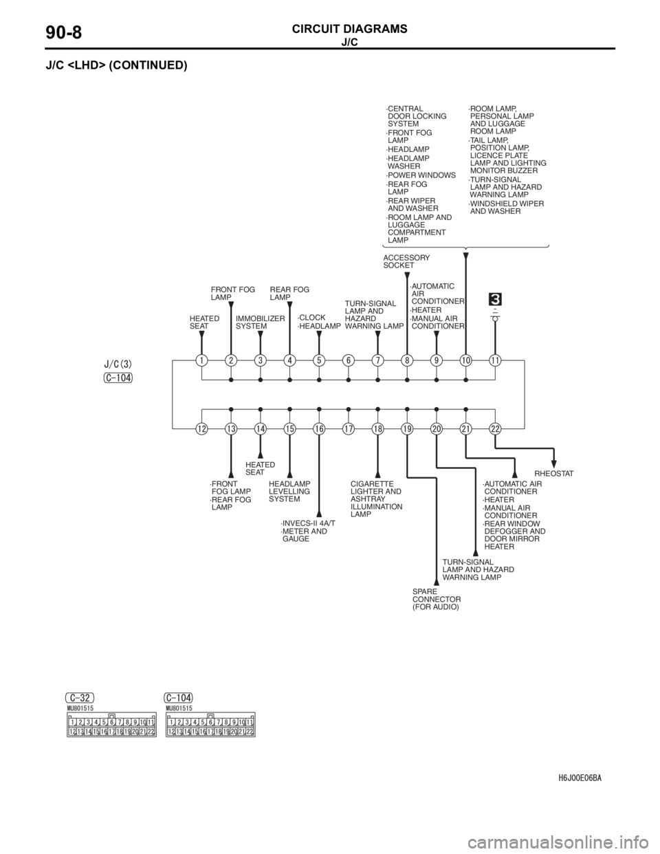
J/C
CIRCUIT DIAGRAMS90-8
J/C
FRONT FOG
LAMP
·FRONT
FOG LAMP·FRONT FOG
LAMP
REAR FOG
LAMP
·REAR FOG
LAMP·REAR FOG
LAMP
HEATED
SEAT
HEATED
SEAT IMMOBILIZER
SYSTEM·CLOCK·HEATER TURN-SIGNAL
LAMP AND
HAZARD
WARNING LAMP·TURN-SIGNAL
LAMP AND HAZARD
WARNING LAMP
TURN-SIGNAL
LAMP AND HAZARD
WARNING LAMP ·MANUAL AIR
CONDITIONER
·HEATER
·MANUAL AIR
CONDITIONER ·HEADLAMP·HEADLAMP
·HEADLAMP
WASHER
ACCESSORY
SOCKET·CENTRAL
DOOR LOCKING
SYSTEM
·POWER WINDOWS
·REAR WIPER
AND WASHER
·ROOM LAMP AND
LUGGAGE
COMPARTMENT
LAMP·ROOM LAMP,
PERSONAL LAMP
AND LUGGAGE
ROOM LAMP
·TAIL LAMP,
POSITION LAMP,
LICENCE PLATE
LAMP AND LIGHTING
MONITOR BUZZER
·WINDSHIELD WIPER
AND WASHER
HEADLAMP
LEVELLING
SYSTEM
·INVECS-II 4A/T
·METER AND
GAUGECIGARETTE
LIGHTER AND
ASHTRAY
ILLUMINATION
LAMP
SPARE
CONNECTOR
(FOR AUDIO)·REAR WINDOW
DEFOGGER AND
DOOR MIRROR
HEATERRHEOSTAT ·AUTOMATIC
AIR
CONDITIONER
·AUTOMATIC AIR
CONDITIONER
Page 473 of 800
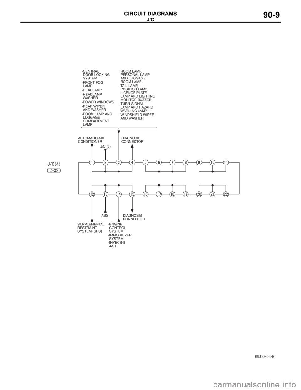
J/C
CIRCUIT DIAGRAMS90-9
·FRONT FOG
LAMP
·TURN-SIGNAL
LAMP AND HAZARD
WARNING LAMP ·HEADLAMP
·HEADLAMP
WASHER ·CENTRAL
DOOR LOCKING
SYSTEM
·POWER WINDOWS
·REAR WIPER
AND WASHER
·ROOM LAMP AND
LUGGAGE
COMPARTMENT
LAMP·ROOM LAMP,
PERSONAL LAMP
AND LUGGAGE
ROOM LAMP
·TAIL LAMP,
POSITION LAMP,
LICENCE PLATE
LAMP AND LIGHTING
MONITOR BUZZER
·WINDSHIELD WIPER
AND WASHER
J/C (6)DIAGNOSIS
CONNECTOR
DIAGNOSIS
CONNECTOR
SUPPLEMENTAL
RESTRAINT
SYSTEM (SRS)ABS
·ENGINE
CONTROL
SYSTEM
·IMMOBILIZER
SYSTEM
·INVECS-II
4A/T AUTOMATIC AIR
CONDITIONER