wheel alignment MITSUBISHI LANCER 2006 Workshop Manual
[x] Cancel search | Manufacturer: MITSUBISHI, Model Year: 2006, Model line: LANCER, Model: MITSUBISHI LANCER 2006Pages: 800, PDF Size: 45.03 MB
Page 165 of 800
TROUBLESHOOTING
WHEEL AND TYRE31-3
TROUBLESHOOTING
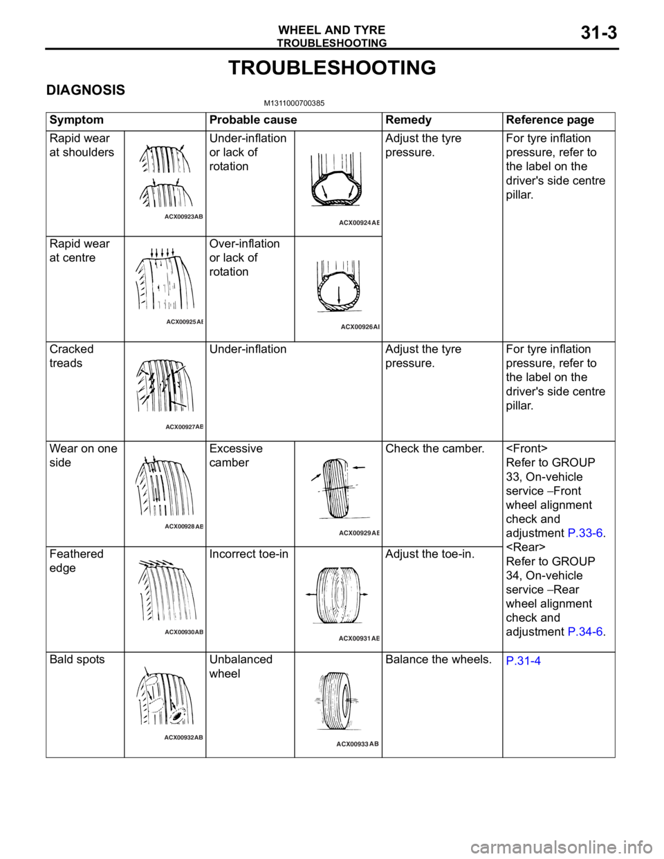
DIAGNOSISM1311000700385
SymptomProbable causeRemedyReference page
Rapid wear
at shoulders
ACX00923AB
Unde
r-inflation
or lack
of
rot
a tion
ACX00924 AB
Adjust the tyre
pre
ssu re.For tyre inflation
pressure, refer to
th
e lab e l on the
driver'
s side centre
pi
lla r .
Rapi d wear
at ce
ntre
ACX00925 AB
Over-infla
tion
or lack
of
rot
a tion
ACX00926 AB
Cra
cke d
treads
ACX00927 AB
Unde
r-inflationAdjust th e tyre
pre
ssu re.For tyre inflation
pressure, refer to
th
e lab e l on the
driver'
s side centre
pi
lla r .
Wear o n one
side
ACX00928
AB
Excessive
cam
b er
ACX00929 AB
Check the camber .
Refer to GROUP
33
, On -vehicle
serv
ic e
− Front
whee
l alignment
check and
ad
justmen t
P.33-6.
Refer to GROUP
34
, On -vehicle
serv
ic e
− Rear
whee
l alignment
check and
ad
justmen t
P.34-6.
Feather ed
edge
ACX00930 AB
In
correct toe- in
ACX00931
AB
Adjust the toe-in.
Bald spot s
ACX00932 AB
Unba
lanced
whee
l
ACX00933 AB
Balance
the whee ls.P.31-4
Page 166 of 800
TROUBLESHOOTING
WHEEL AND TYRE31-4
WHEEL BALANCE ACCURACY
M1311001700247
PURPOSE
This section contains tips and procedures for achiev-
ing accurate wheel balance. Steering wheel vibration
and/or body shake can result if any of these proce
-
dures are not carefully observed.
1. Wheels and tyres must be properly mounted on a balancer in order to achieve correct balance.
Centring the wheel on the shaft of the balancer is
essential for proper mounting.
2. Off-the-car wheel balancers must be calibrated periodically to ensure good balancing results. An
inaccurately calibrated balancer could cause
unnecessary replacement of tyres, shocks,
suspension components, or steering components.
Check your balancer's calibration approximately
every 100 balances. Your wheel balancer's instruc
-
tion manual should include calibration procedures. If
the calibration procedures specifically for your bal
-
ancer are missing, use the generic steps in this sec-
tion for zero calibration, static balance, and dynamic
balance checks. The wheel balancer calibration
checks are also described in the flowchart. (Refer to
P.31-6).
PROCEDURE
1. Confirm that the balancer's cone and the wheel
mounting cone are undamaged and free of dirt
and rust.
2. On this vehicle, the wheel's centre hole on the hub side has a chamfered edge. Use a
back-mounting cone on your wheel balancer to
centre the wheel on the balancer shaft.
3. Install a wheel mounting cone. The appropriate size cone for this vehicle is 67.0 mm.
4. Before balancing the wheel, remove any wheel weights from both sides. Also check both sides for
any damage.
5. When installing wheel weights, hammer them at a straight (not diagonal) angle.
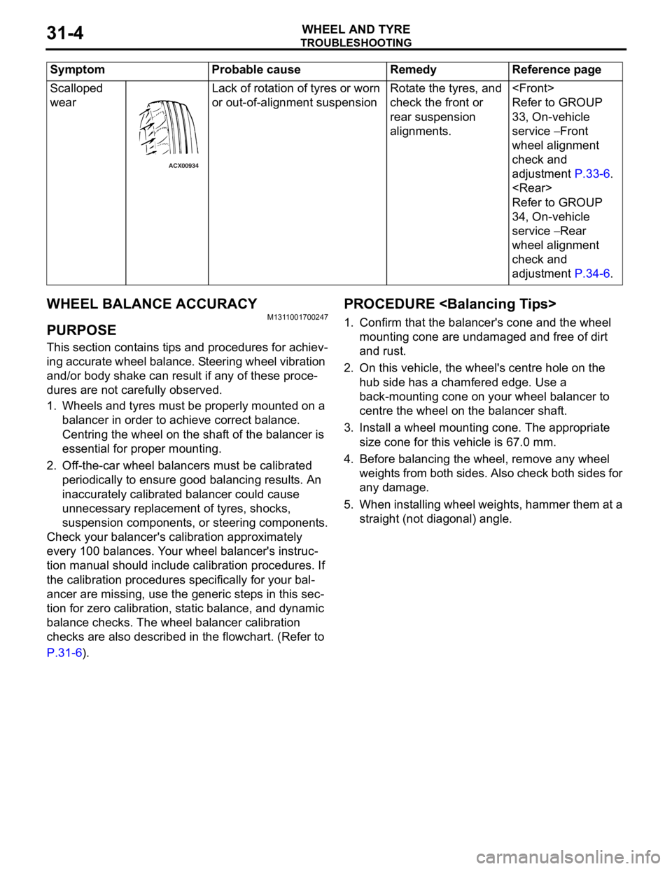
Scalloped
wear
ACX00934
Lack of rot a tio n of tyres or worn
or out-of-a
lign m ent suspensionRota te th e tyre s, an d
check the f
r ont or
rea
r suspension
alignment
s.
Refer to GROUP
33
, On -vehicle
serv
ic e
− Front
whee
l alignment
check and
ad
justmen t
P.33-6.
Refer to GROUP
34
, On -vehicle
serv
ic e
− Rear
whee
l alignment
check and
ad
justmen t
P.34-6.
Sy mptom P robable cause Reme dy Referen ce p a g e
Page 178 of 800
CROSSMEMBER
POWER PLANT MOUNT32-8
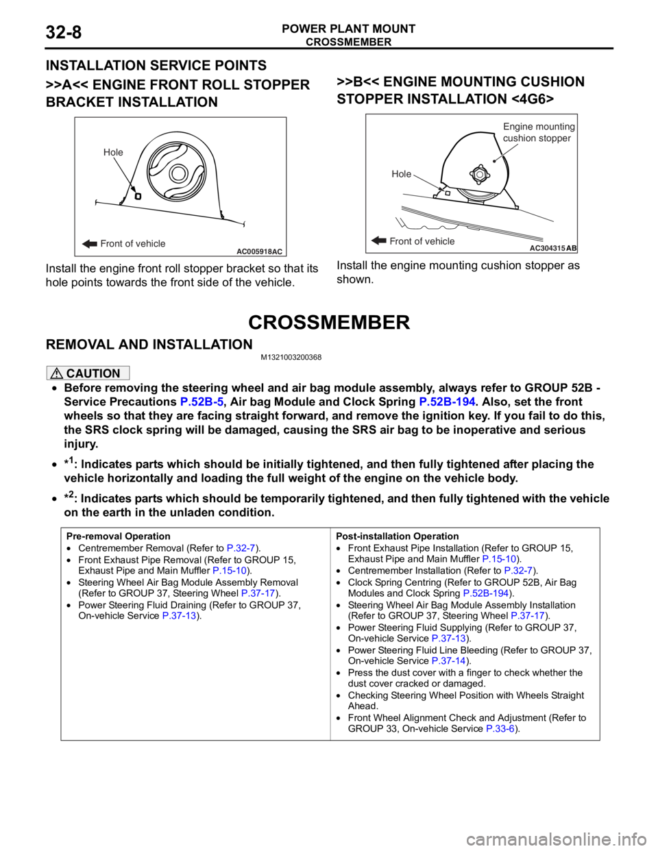
INSTALLATION SERVICE POINTS
>>A<< ENGINE FRONT ROLL STOPPER
BRACKET INSTALLATION
AC005918Front of vehicleHoleAC
Inst
all th e en gine fron t roll stop per b r acket so that it s
hole
point s towards the fro n t side of the vehicle.
>>B<< ENGINE MOUNTING CUSHION
ST
OPPER INST ALLA TION <4G6>
AC304315ABFront of vehicle
Hole Engine mounting
cushion stopper
Inst
all the e ngin e mo untin g cushio n sto pper a s
shown.
CROSSMEMBER
REMOVA L AND INST ALLA TIONM13210032 0036 8
CAUTION
•Before removing the steering wheel and air bag module assembly, always refer to GROUP 52B -
Service Precautions
P.52B-5, Air bag Module and Clock Spring P.52B-194. Also, set the front
wheels so that they are facing straight forward, and remove the ignition key. If you fail to do this,
the SRS clock spring will be damaged, causing the SRS air bag to be inoperative and serious
injury.
•*1: Indicates parts which should be initially tightened, and then fully tightened after placing the
vehicle horizontally and loading the full weight of the engine on the vehicle body.
•
Pre-removal Operation
•Centremember Removal (Refer to P.32-7).
•Front Exhaust Pipe Remova l (Refer to GROUP 15,
Exhaust Pipe and Main Muffler P.15-10).
•Steering Wheel Air Bag Mo dule Assembly Removal
(Refer to GROUP 37, Steering Wheel P.37-17).
•Power Steering Fluid Draining (Refer to GROUP 37,
On-vehicle Service P.37-13).
Post-installation Operation
•Front Exhaust Pipe Installation (Refer to GROUP 15,
Exhaust Pipe and Main Muffler
P.15-10).
•Centremember Installation (Refer to P.32-7).
•Clock Spring Centring (Refer to GROUP 52B, Air Bag
Modules and Clock Spring P.52B-194).
•Steering Wheel Air Bag Module Assembly Installation
(Refer to GROUP 37, Steering Wheel P.37-17).
•Power Steering Fluid Supplying (Refer to GROUP 37,
On-vehicle Service P.37-13).
•Power Steering Fluid Line Bleeding (Refer to GROUP 37,
On-vehicle Service P.37-14).
•Press the dust cover with a finger to check whether the
dust cover cracked or damaged.
•Checking Steering Wheel Position with Wheels Straight
Ahead.
•Front Wheel Alignment Check and Adjustment (Refer to
GROUP 33, On-vehicle Service P.33-6).
*2: Indicates parts which should be temporarily tightened, and then fully tightened with the vehicle
on the earth in the unladen condition.
Page 183 of 800
33-1
GROUP 33
FRONT
SUSPENSION
CONTENTS
GENERAL INFORMATIO N . . . . . . . .33-2
SERVICE SPECIFICATIONS . . . . . . .33-3
LUBRICANT . . . . . . . . . . . . . . . . . . . .33-3
SPECIAL TOOLS . . . . . . . . . . . . . . . .33-4
ON-VEHICLE SERVICE . . . . . . . . . . .33-6
FRONT WHEEL ALIGNMENT CHECK AND
ADJUSTMENT . . . . . . . . . . . . . . . . . . . . . . 33-6
LOWER ARM BALL JOINT AXIAL PLAY
CHECK . . . . . . . . . . . . . . . . . . . . . . . . . . . . 33-7
LOWER ARM BALL JOINT COVER
CHECK . . . . . . . . . . . . . . . . . . . . . . . . . . . . 33-7
STRUT ASSEMBLY . . . . . . . . . . . . . .33-7
REMOVAL AND INSTALLATION . . . . . . . . 33-7
INSPECTION. . . . . . . . . . . . . . . . . . . . . . . . 33-7
DISASSEMBLY AND REASSEMBLY . . . . . 33-8
INSPECTION. . . . . . . . . . . . . . . . . . . . . . . . 33-10
LOWER ARM . . . . . . . . . . . . . . . . . . .33-11
REMOVAL AND INSTALLATION . . . . . . . . 33-11
INSPECTION. . . . . . . . . . . . . . . . . . . . . . . . 33-12
LOWER ARM BALL JOINT COVER
REPLACEMENT . . . . . . . . . . . . . . . . . . . . . 33-12
LOWER ARM BUSHING (REAR)
REPLACEMENT . . . . . . . . . . . . . . . . . . . . . 33-13
STABILIZER BAR. . . . . . . . . . . . . . . .33-14
REMOVAL AND INSTALLATION . . . . . . . . 33-14
INSPECTION. . . . . . . . . . . . . . . . . . . . . . . . 33-16
WARNINGS REGARDING SERVICING OF SUPPLEMENTAL RESTRAINT SYSTEM (SRS) EQUIPPED VEHICLES
WARNING
•Improper service or maintenance of any component of the SRS, or any SRS-related component, can lead to
personal injury or death to service personnel (from inad vertent firing of the air bag) or to the driver and
paassenger (from rendering the SRS inoperative).
•Service or maintenance of any SRS component or SRS-related component must be performed only at an
authorized MITSUBISHI dealer.
•MITSUBISHI dealer personnel must thoroughly review this manual, and especially its GROUP 52B - Supplemental
Restraint System (SRS) before beginning any service or maintenance of any component of the SRS or any
SRS-related component.
NOTE
The SRS includes the following components: SRS air bag control unit, SRS warning light, front impact sensors, air bag module,
clock spring, and interconnecting wiring. Other SRS-related components (that may have to be removed/installed in connection
with SRS service or maintenance) are indicated in the table of contents by an asterisk (*).
Page 188 of 800
ON-VEHICLE SERVICE
FRONT SUSPENSION33-6
ON-VEHICLE SERVICE
FRONT WHEEL ALIGNMENT CHECK AND
ADJUSTMENT
M1331000900886
Measure wheel alignment with alignment equipment
on a level surface. The front suspension, steering
system, wheels, and tyres should be serviced to nor
-
mal condition before measuring wheel alignment.
TOE-IN
Standard value:
At the centre of tyre tread: 1 ± 2 mm
Toe angle (per wheel): 0°03' ± 0°06'
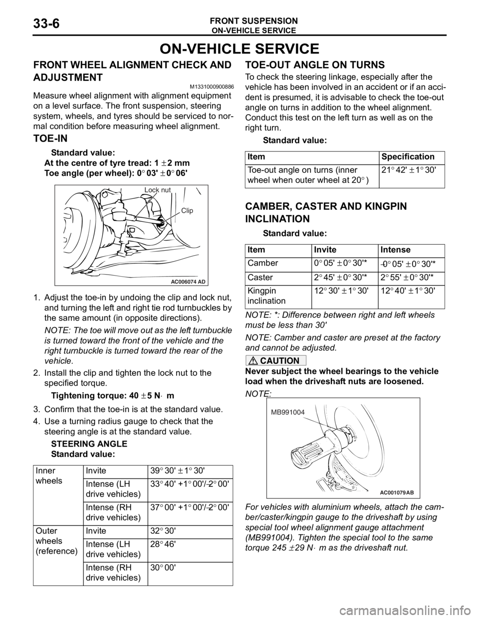
AC006074 AD
Lock nut
Clip
1.Adjust the to e-in by undoing th e clip and lock nut,
and turning th e lef t and rig h t tie rod turnbu ckles by
th e same amount (in op posite direct ions).
NOTE: The toe will move out as th e lef t turnbuckle
is turn
ed toward the fro n t of th e ve hicle an d the
right tu
rnbuckle is turned t o ward the rear of the
vehicle.
2. In st all the clip and tighten the lock nut to the
specifie d torqu e .
Ti ghte n ing torque: 40 ± 5 N⋅m
3.Conf irm t hat the toe-in is at the st anda rd value.
4.Use a turn ing ra dius gaug e to check tha t the
steering ang le is at the st an dard value .
STEE R I N G AN G L E
St andard va lue:
Inner
wheelsInvite39°30' ± 1°30'
Intense (LH
drive vehicles)33°40' +1°00'/−2°00'
Intense (RH
drive vehicles)37°00' +1°00'/−2°00'
Outer
wheels
(reference)Invite32°30'
Intense (LH
drive vehicles)28°46'
Intense (RH
drive vehicles)30°00'
TO E-OUT ANGLE ON TURNS
To check the stee ring linkage, e s pe cially af ter the
vehicle has been invo
lve d in an accid ent or if an a cci
-
dent is pres umed, it is advisab le to check th e toe-ou t
angle
on tu rns in addition to the wh eel a lig nmen t.
Conduct this test on th e lef t tu rn as we ll a s on the
right turn.
St andard va lue:
ItemSpecification
Toe-out angle on turns (inner
wheel when outer wheel at 20
°)
21°42' ± 1°30'
CAMBER, CASTER AND KINGPIN
INCLINA
T ION
St andard va lue:
ItemInviteIntense
Camber0°05' ± 0°30'*−0°05' ± 0°30'*
Caster2°45' ± 0°30'*2°55' ± 0°30'*
Kingpin
inclination12°30' ± 1°30'12°40' ± 1°30'
NOTE: *: Diffe rence between right and lef t wheels
must be less than 30'
NOTE: Camber and caster are prese t at th e factory
and cannot be adjust ed.
CAUTION
Never subject the wheel bearings to the vehicle
load when the driveshaft nuts are loosened.
NOTE:
AC001079
MB991004
AB
For vehicles with aluminium wheels, attach the cam-
ber/caster/kingpin gauge to the driveshaft by using
special tool wheel alignment gauge attachment
(MB991004). Tighten the special tool to the same
torque 245
± 29 N⋅m as the driveshaft nut.
Page 189 of 800
STRUT ASSEMBLY
FRONT SUSPENSION33-7
LOWER ARM BALL JOINT AXIAL PLAY
CHECK
M1332011300074
1. Raise the vehicle.
2. Remove the stabilizer link from the lower arm.
3. Move the lower arm up and down with your hands to check for an excessive play in the axial
direction of the ball joint. If there is an excessive
play, replace the lower arm assembly.
LOWER ARM BALL JOINT COVER
CHECK
M1332008600321
1. Press the lower arm ball joint cover with your finger to check that there are no cracks or
damage in the lower arm ball joint cover.
2. If the lower arm ball joint cover is cracked or damaged, replace the lower arm assembly.
NOTE: If the lower arm ball joint cover is cracked
or damaged, it is possible that there may also be
damage to the ball joint.
STRUT ASSEMBLY
REMOVAL AND INSTALLATION
M1332001100325
Post-installation Operation
•Front Wheel Alignment Adjustment (Refer to P.33-6).
AC304153
44 ± 5 N·m
1 2
3
4
N
AB
167 ± 9 N·m
5
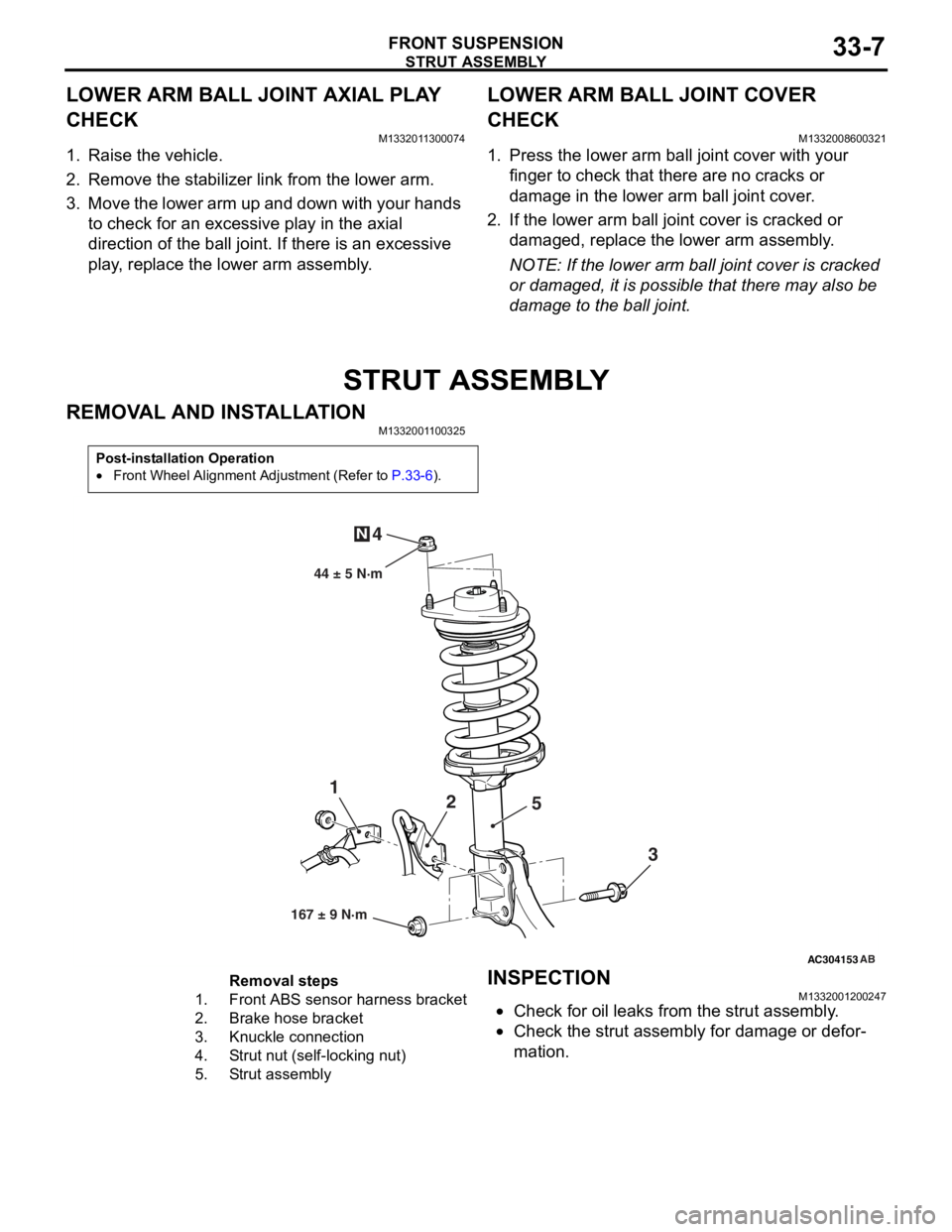
Removal steps
1.Front ABS sensor
harness bracket
2.Brake hose bracket
3.Knuckle connection
4.Strut nut (self-locking nut)
5.Strut assembly
INSPECTION
M13320012 0024 7
•Check for oil leaks fro m the stru t assemb ly .
•Check the stru t assemb ly for damage o r defor-
mation.
Page 193 of 800
LOWER ARM
FRONT SUSPENSION33-11
LOWER ARM
REMOVAL AND INSTALLATIONM1332001600331
CAUTION
*: Indicates parts which should be temporarily tightened, and then fully tightened with the vehicle on
the earth in an unladen condition.
Post-installation Operation
•Check the lower arm ball join t cover for cracks or damage
by pushing it with your finger.
•Front Wheel Alignment Check and Adjustment (Refer to
P.33-6).
AC006097 AD
7
1
3 4
5
108 ± 10 N·m
186 ± 10 N·m*
7
3
6
N
Specified grease :
Multipurpose grease SAE J310,
NLGI No.2 or equivalent
167 ± 9 N·m
6
2
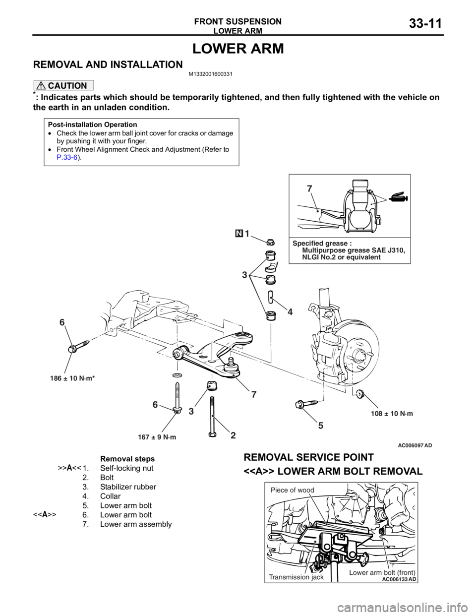
Removal steps
>>A<<1.Self-locking nut
2.Bolt
3.Stabilizer rubber
4.Collar
5.Lower arm bolt
<>6.Lower arm bolt
7.Lower arm assembly
REMOVAL SERVICE POINT
<> LOWER ARM BOLT REMOVAL
AC006133
ADLower arm bolt (front)Transmission jackPiece of wood
Page 196 of 800
STABILIZER BAR
FRONT SUSPENSION33-14
STABILIZER BAR
REMOVAL AND INSTALLATIONM1332004000673
CAUTION
•Before removing the steering wheel and air bag module assembly, refer to GROUP 52B, Service
Precautions
P.52B-5 and Air Bag Module and Clock Spring P.52B-194. Also, put the front wheels in
straight-ahead position. Failure to do so may damage the SRS clock spring and render the SRS air
bag inoperative, which results serious driver injury.
•
Pre-removal Operation
•Steering Wheel and Air Bag Module Assembly Removal
(Comfort: refer to GROUP 37, Steering Wheel
P.37-17/Sport: refer to GROUP 37, Steering Wheel P.37-18).•Clock Spring Removal (Refer to GROUP 52B, Air Bag
Modules and Clock Spring P.52B-194).
•Centermember Removal (Ref er to GROUP 32, Engine
Roll Stopper, Centermember P.32-7).
•Front Exhaust Pipe Remova l (Refer to GROUP 15,
Exhaust Pipe and Main Muffler P.15-10).
Post-installation Operation
•Front Exhaust Pipe Installation (Refer to GROUP 15,
Exhaust Pipe and Main Muffler P.15-10).•Centermember Installation (Refer to GROUP 32, Engine
Roll Stopper, Centermember P.32-7).
•Clock Spring Installation (Refer to GROUP 52B, Air Bag
Modules and Clock Spring P.52B-194).
•Steering Wheel and Air Bag Module Assembly Installation
(Comfort: refer to GROUP 37, Steering Wheel
P.37-17/Sport: refer to GROUP 37, Steering Wheel P.37-18).•Check the dust covers for cracks or damage by pushing it
with your finger.
•Checking Steering Wheel Position with Wheels Straight
Ahead
•Front Wheel Alignment Check and Adjustment (Refer to P.33-6).
AC006139 AE
49 ± 10 N·m 108 ± 10 N·m
167 ± 9 N·m
167 ± 9 N·m
52 ± 7 N·m* 25 ± 5 N·m
21 ± 4 N·m
18 ± 2 N·m
10
9
4
5 1
2
2
3
7
6
2
11
8
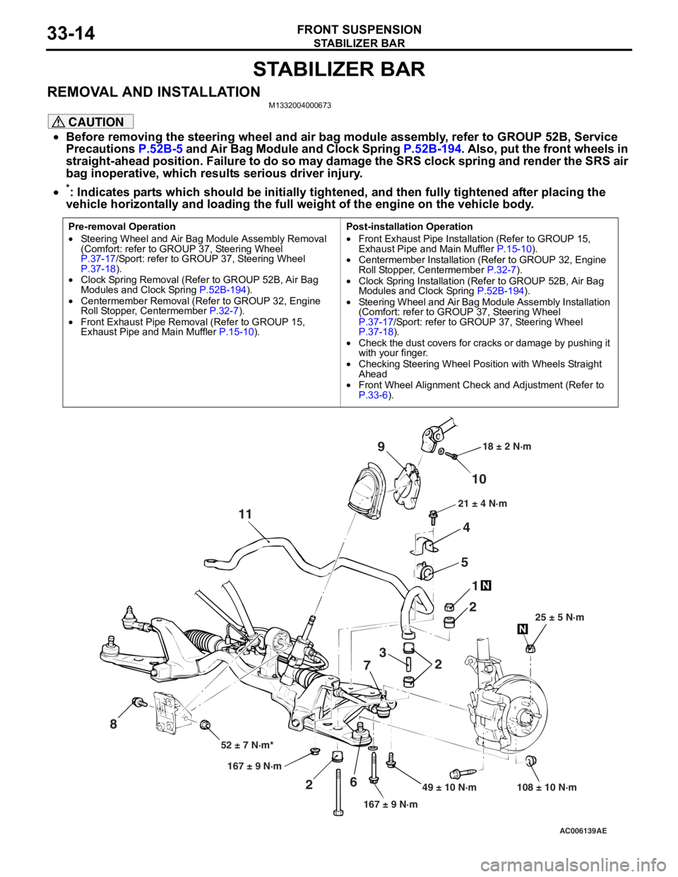
*: Indicates parts which should be initially tightened, and then fully tightened after placing the
vehicle horizontally and loading the full weight of the engine on the vehicle body.
Page 199 of 800
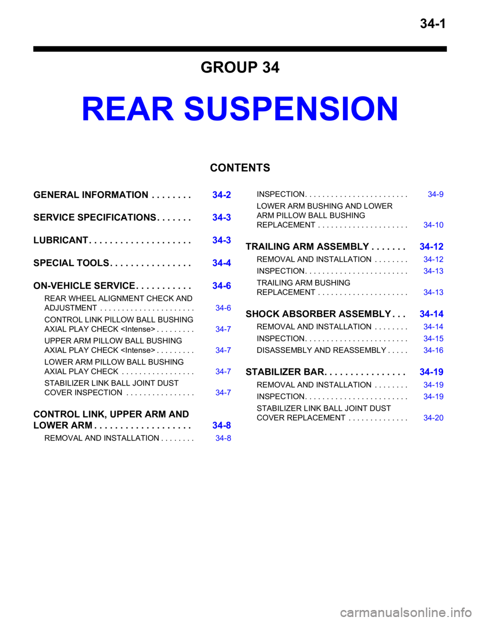
34-1
GROUP 34
REAR SUSPENSION
CONTENTS
GENERAL INFORMATION . . . . . . . .34-2
SERVICE SPECIFICATIONS . . . . . . .34-3
LUBRICANT . . . . . . . . . . . . . . . . . . . .34-3
SPECIAL TOOLS . . . . . . . . . . . . . . . .34-4
ON-VEHICLE SERVICE . . . . . . . . . . .34-6
REAR WHEEL ALIGNMENT CHECK AND
ADJUSTMENT . . . . . . . . . . . . . . . . . . . . . . 34-6
CONTROL LINK PILLOW BALL BUSHING
AXIAL PLAY CHECK
UPPER ARM PILLOW BALL BUSHING
AXIAL PLAY CHECK
LOWER ARM PILLOW BALL BUSHING
AXIAL PLAY CHECK . . . . . . . . . . . . . . . . . 34-7
STABILIZER LINK BALL JOINT DUST
COVER INSPECTION . . . . . . . . . . . . . . . . 34-7
CONTROL LINK, UPPER ARM AND
LOWER ARM . . . . . . . . . . . . . . . . . . .34-8
REMOVAL AND INSTALLATION . . . . . . . . 34-8
INSPECTION. . . . . . . . . . . . . . . . . . . . . . . . 34-9
LOWER ARM BUSHING AND LOWER
ARM PILLOW BALL BUSHING
REPLACEMENT . . . . . . . . . . . . . . . . . . . . . 34-10
TRAILING ARM ASSEMBLY . . . . . . .34-12
REMOVAL AND INSTALLATION . . . . . . . . 34-12
INSPECTION. . . . . . . . . . . . . . . . . . . . . . . . 34-13
TRAILING ARM BUSHING
REPLACEMENT . . . . . . . . . . . . . . . . . . . . . 34-13
SHOCK ABSORBER ASSEMBLY . . .34-14
REMOVAL AND INSTALLATION . . . . . . . . 34-14
INSPECTION. . . . . . . . . . . . . . . . . . . . . . . . 34-15
DISASSEMBLY AND REASSEMBLY . . . . . 34-16
STABILIZER BAR. . . . . . . . . . . . . . . .34-19
REMOVAL AND INSTALLATION . . . . . . . . 34-19
INSPECTION. . . . . . . . . . . . . . . . . . . . . . . . 34-19
STABILIZER LINK BALL JOINT DUST
COVER REPLACEMENT . . . . . . . . . . . . . . 34-20
Page 204 of 800
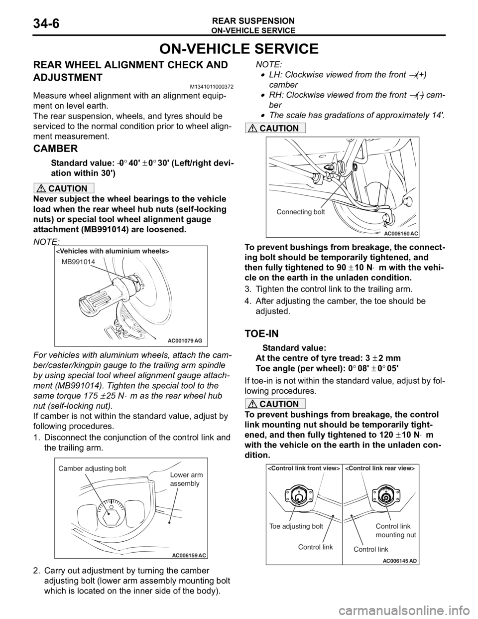
ON-VEHICLE SERVICE
REAR SUSPENSION34-6
ON-VEHICLE SERVICE
REAR WHEEL ALIGNMENT CHECK AND
ADJUSTMENT
M1341011000372
Measure wheel alignment with an alignment equip-
ment on level earth.
The rear suspension, wheels, and tyres should be
serviced to the normal condition prior to wheel align
-
ment measurement.
CAMBER
Standard value: −0°40' ± 0°30' (Left/right devi-
ation within 30')
CAUTION
Never subject the wheel bearings to the vehicle
load when the rear wheel hub nuts (self-locking
nuts) or special tool wheel alignment gauge
attachment (MB991014) are loosened.
NOTE:
AC001079
MB991014
AG
For vehicles with aluminium wheels, attach the cam-
ber/caster/kingpin gauge to the trailing arm spindle
by using special tool wheel alignment gauge attach
-
ment (MB991014). Tighten the special tool to the
same torque 175
± 25 N⋅m as the rear wheel hub
nut (self-locking nut).
If camber is not within the standard value, adjust by
following procedures.
1. Disconnect the conjunction of the control link and the trailing arm.
AC006159 AC
Camber adjusting bolt
Lower arm
assembly
2. Carry out adjustment by turning the camber
adjusting bolt (lower arm assembly mounting bolt
which is located on the inner side of the body).
NOTE: .
•LH: Clockwise viewed from the front → (+)
camber
•RH: Clockwise viewed from the front → (−) cam-
ber
•
AC006160 AC
Connecting bolt
The scale has gradations of approximately 14'.
CAUTION
To prevent bushings from breakage, the connect-
ing bolt should be temporarily tightened, and
then fully tightened to 90
± 10 N⋅m with the vehi-
cle on the earth in the unladen condition.
3. Tighten the control link to the trailing arm.
4. After adjusting the camber, the toe should be
adjusted.
TOE-IN
Standard value:
At the centre of tyre tread: 3 ± 2 mm
Toe angle (per wheel): 0°08' ± 0°05'
If toe-in is not within the standard value, adjust by fol-
lowing procedures.
CAUTION
To prevent bushings from breakage, the control
link mounting nut should be temporarily tight
-
ened, and then fully tightened to 120 ± 10 N⋅m
with the vehicle on the earth in the unladen con
-
dition.
AC006145 AD
Control link
Toe adjusting boltControl link
Control link
mounting nut