clock MITSUBISHI LANCER 2014 8.G Owner's Manual
[x] Cancel search | Manufacturer: MITSUBISHI, Model Year: 2014, Model line: LANCER, Model: MITSUBISHI LANCER 2014 8.GPages: 434, PDF Size: 57.5 MB
Page 338 of 434
General information about your radio
Comfort controls 7-63
7
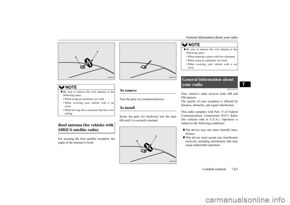
For securing the best satellite reception, the angle of the antenna is fixed.
Turn the pole (A) counterclockwise. Screw the pole (A) clockwise into the base (B) until it is securely retained.
N00733901478
Your vehicle’s radio receives both AM andFM stations.The quality of your reception is affected by distance, obstacles, and signal interference. This radio complies with Part 15 of Federal Communications Commission (FCC) Rules(for vehicles sold in U.S.A.). Operation is subject to the following conditions: The device may not cause harmful inter- ference. This device must accept any interference recieved, including interference that may cause undesirable operation.
NOTE
Be sure to remove the roof antenna in the following cases: • When using an automatic car wash• When covering your vehicle with a car cover • When driving into a structure that has a low ceiling
Roof antenna (for vehicles with SIRIUS satellite radio)
To remove To install
NOTE
Be sure to remove the roof antenna in the following cases: • When entering a place with low clearance • When using an automatic car wash • When covering your vehicle with a car cover
General information about your radio
Page 346 of 434
Tools and jack
For emergencies 8-5
8
5. If you do not see steam or spray coming from under the hood, leave the engine on until the bar graph for the engine coolant temperature warning display on the multi-information display goes down. When it is in the middle of the normal zone, you can start driving again. If the bar graphstays in the red zone, turn off the engine. 6. When you do not see any more steam or spray, open the hood. Look for obvious leaks, such as a split radiator hose. Be careful as components will be hot. Anyleak source must be repaired. 7. If there is no obvious leak source, check the coolant level in the reserve tank. Ifthere is none, or if it is too low, slowly add coolant.
8. If the reserve tank needs coolant, you will probably also need to add coolant to the radiator. Do not loosen or remove the radiator cap until the engine has cooleddown. 9. Start the engine, and slowly add coolant, up to the bottom of the filler neck. Useplain water if you have to (and replace it with the right coolant as soon as possible).
10. Replace the radiator cap and tighten it
fully. Check the engine coolant tempera- ture display on the multi-information dis- play. You can start driving again when thebar graph for the engine coolant tempera- ture display returns to the normal zone.
11. Have your vehicle checked by your autho-
rized Mitsubishi Motors dealer or a repair facility of your choice.
N00836600265
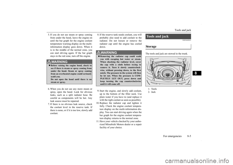
The tools and jack are stowed in the trunk.
WA R N I N G Before raising the engine hood, check to see if there is steam or spray coming fromunder the hood. Steam or spray coming from an overheated engine could seriously scald you.Do not open the hood until there is no steam or spray.
WA R N I N G Removing the radiator cap could scald you with escaping hot water or steam.When checking the radiator level, cover the cap with a cloth before trying to remove it. Turn it slowly counterclock-wise, without pressing down, to the first notch. The pressure in the system will then be let out. When the pressure is COM-PLETELY LET OUT, press down and keep turning the cap counterclockwise until it will come off.
Tools and jack Storage 1- Tools 2- Jack
Page 349 of 434
How to change a tire 8-8 For emergencies
8
N00849701300
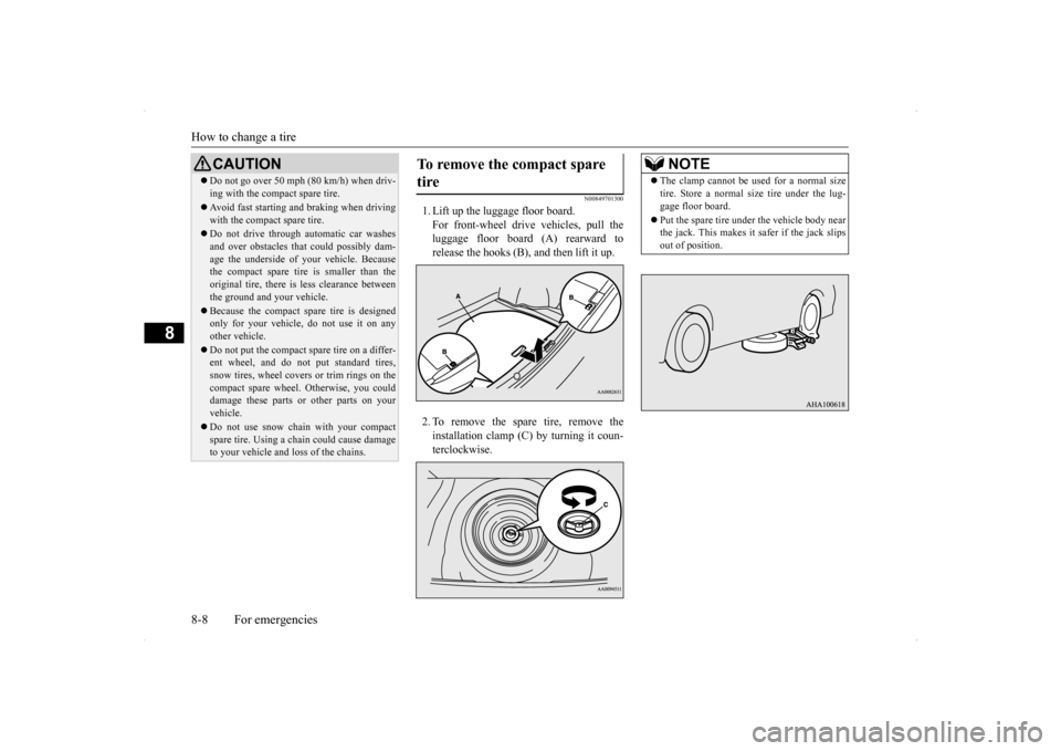
1. Lift up the luggage floor board. For front-wheel drive vehicles, pull the luggage floor board (A) rearward to release the hooks (B), and then lift it up. 2. To remove the spare tire, remove the installation clamp (C) by turning it coun-terclockwise.
Do not go over 50 mph (80 km/h) when driv- ing with the compact spare tire. Avoid fast starting and braking when driving with the compact spare tire. Do not drive through automatic car washes and over obstacles that could possibly dam-age the underside of your vehicle. Because the compact spare tire is smaller than the original tire, there is less clearance betweenthe ground and your vehicle. Because the compact spare tire is designed only for your vehicle, do not use it on any other vehicle. Do not put the compact spare tire on a differ- ent wheel, and do not put standard tires, snow tires, wheel covers or trim rings on thecompact spare wheel. Otherwise, you could damage these parts or other parts on your vehicle. Do not use snow chain with your compact spare tire. Using a chain could cause damageto your vehicle and loss of the chains.CAUTION
To remove the compact spare tire
NOTE
The clamp cannot be used for a normal size tire. Store a normal size tire under the lug- gage floor board. Put the spare tire under the vehicle body near the jack. This makes it safer if the jack slips out of position.
Page 352 of 434
![MITSUBISHI LANCER 2014 8.G Owners Manual How to change a tire
For emergencies 8-11
8
7. [Vehicle with steel wheels] • Normal wheels and compact spare wheel Install the wheel nuts (tapered nuts) with their tapered ends facing inward, thent MITSUBISHI LANCER 2014 8.G Owners Manual How to change a tire
For emergencies 8-11
8
7. [Vehicle with steel wheels] • Normal wheels and compact spare wheel Install the wheel nuts (tapered nuts) with their tapered ends facing inward, thent](/img/19/7460/w960_7460-351.png)
How to change a tire
For emergencies 8-11
8
7. [Vehicle with steel wheels] • Normal wheels and compact spare wheel Install the wheel nuts (tapered nuts) with their tapered ends facing inward, thentighten by hand until the wheel is no lon- ger loose. [Vehicle with aluminum wheels] • Normal wheelsTemporarily tighten the wheel nuts(flange nuts) until their flange section comes in contact with the wheel and it is no longer loose.
• Compact spare wheel Install the wheel nuts with their taperedends facing inward, then tighten by hand until the wheel is no longer loose.
8. Lower the vehicle slowly by rotating the wheel nut wrench counterclockwise until the tire touches the ground.
CAUTION Never apply oil to either the wheel bolts or the nuts or they will tighten too much.
NOTE
Flange nuts can be temporarily used on the compact spare or steel wheel, but return them to the original wheel and tire as soon as possible. If all four wheels are changed to steel wheels, use tapered nuts.
Page 373 of 434
Power steering fluid (if so equipped) 9-14 Vehicle care and maintenance
9
N00939000388
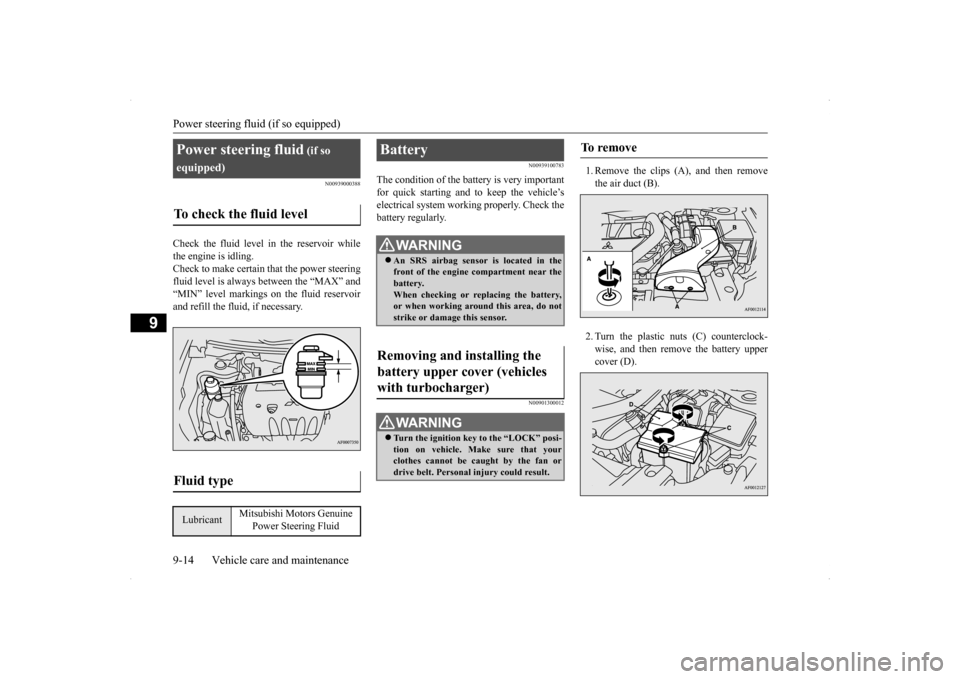
Check the fluid level in the reservoir while the engine is idling. Check to make certain that the power steering fluid level is always between the “MAX” and“MIN” level markings on the fluid reservoirand refill the fluid, if necessary.
N00939100783
The condition of the battery is very importantfor quick starting and to keep the vehicle’selectrical system working properly. Check the battery regularly.
N00901300012
1. Remove the clips (A), and then removethe air duct (B). 2. Turn the plastic nuts (C) counterclock- wise, and then remove the battery uppercover (D).
Power steering fluid
(if so
equipped)To check the fluid level
Fluid type
Lubricant
Mitsubishi Motors Genuine
Power Steering Fluid
Battery
WA R N I N G An SRS airbag sensor is located in the front of the engine compartment near the battery. When checking or replacing the battery,or when working around this area, do not strike or damage this sensor.
Removing and installing the battery upper cover (vehicles with turbocharger)
WA R N I N G Turn the ignition key to the “LOCK” posi- tion on vehicle. Make sure that your clothes cannot be caught by the fan or drive belt. Personal injury could result.
To remove
Page 395 of 434
Replacement of light bulbs 9-36 Vehicle care and maintenance
9
N00943100872
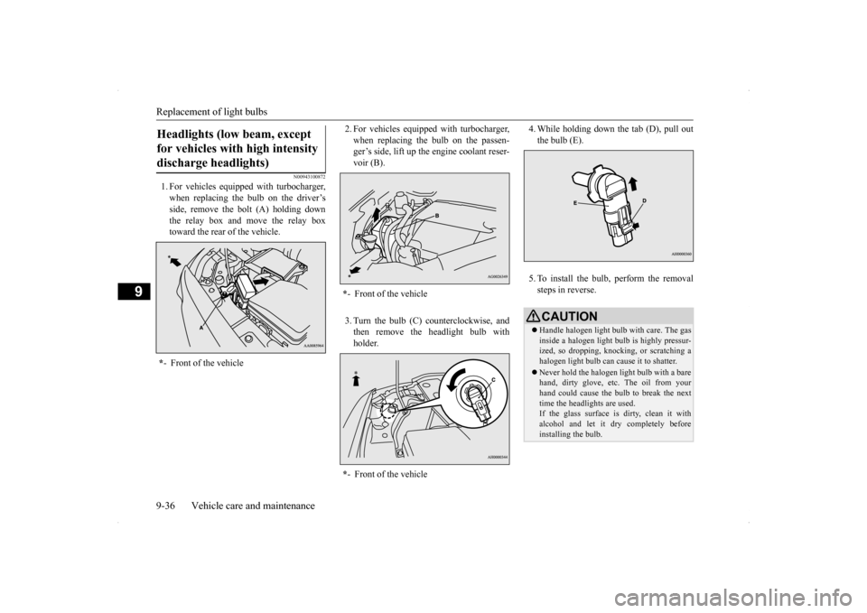
1. For vehicles equipped with turbocharger, when replacing the bulb on the driver’s side, remove the bolt (A) holding downthe relay box and move the relay box toward the rear of the vehicle.
2. For vehicles equipped with turbocharger, when replacing the bulb on the passen- ger’s side, lift up the engine coolant reser- voir (B). 3. Turn the bulb (C) counterclockwise, and then remove the headlight bulb with holder.
4. While holding down
the tab (D), pull out
the bulb (E). 5. To install the bulb, perform the removal steps in reverse.
Headlights (low beam, except for vehicles with high intensity discharge headlights) * - Front of the vehicle
*- Front of the vehicle * - Front of the vehicle
CAUTIONHandle halogen light bulb with care. The gas inside a halogen light bulb is highly pressur- ized, so dropping, knocking, or scratching ahalogen light bulb can cause it to shatter. Never hold the halogen light bulb with a bare hand, dirty glove, etc. The oil from your hand could cause the bulb to break the next time the headlights are used. If the glass surface is dirty, clean it with alcohol and let it dry completely before installing the bulb.
Page 396 of 434
Replacement of light bulbs
Vehicle care and maintenance 9-37
9
N00943100885
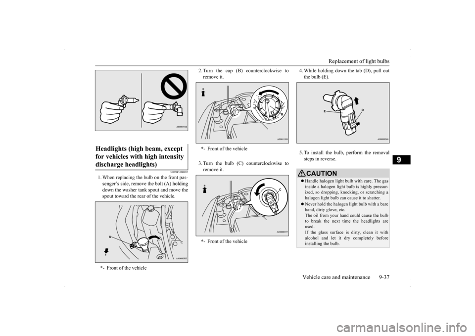
1. When replacing the bulb on the front pas- senger’s side, remove the bolt (A) holdingdown the washer tank spout and move thespout toward the rear of the vehicle.
2. Turn the cap (B) counterclockwise to remove it. 3. Turn the bulb (C) counterclockwise to remove it.
4. While holding down
the tab (D), pull out
the bulb (E). 5. To install the bulb, perform the removal steps in reverse.
Headlights (high beam, except for vehicles with high intensity discharge headlights) * - Front of the vehicle
*- Front of the vehicle * - Front of the vehicle
CAUTIONHandle halogen light bulb with care. The gas inside a halogen light bulb is highly pressur- ized, so dropping, knocking, or scratching ahalogen light bulb can cause it to shatter. Never hold the halogen light bulb with a bare hand, dirty glove, etc. The oil from your hand could cause the bulb to break the next time the headlights areused. If the glass surface is dirty, clean it with alcohol and let it dry completely beforeinstalling the bulb.
Page 397 of 434
Replacement of light bulbs 9-38 Vehicle care and maintenance
9
N00900300103
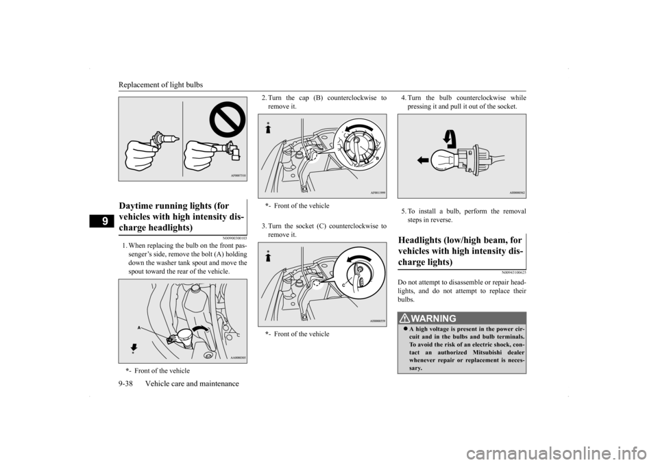
1. When replacing the bulb on the front pas- senger’s side, remove the bolt (A) holdingdown the washer tank spout and move thespout toward the rear of the vehicle.
2. Turn the cap (B) counterclockwise to remove it. 3. Turn the socket (C) counterclockwise to remove it.
4. Turn the bulb counterclockwise while pressing it and pull it out of the socket. 5. To install a bulb, perform the removal steps in reverse.
N00943100625
Do not attempt to disassemble or repair head- lights, and do not attempt to replace their bulbs.
Daytime running lights (for vehicles with high intensity dis- charge headlights) * - Front of the vehicle
*- Front of the vehicle * - Front of the vehicle
Headlights (low/high beam, for vehicles with high intensity dis- charge lights)
WA R N I N G A high voltage is present in the power cir- cuit and in the bulbs and bulb terminals. To avoid the risk of an electric shock, con-tact an authorized Mitsubishi dealer whenever repair or replacement is neces- sary.
Page 398 of 434
Replacement of light bulbs
Vehicle care and maintenance 9-39
9
N00943200121
The alignment of the headlights should be checked by an authorized Mitsubishi Motorsdealer or a repair facility of your choice.
N00917300512
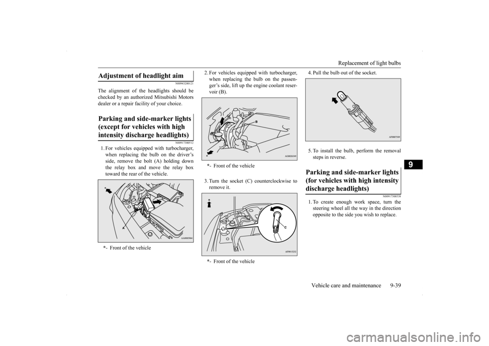
1. For vehicles equipped with turbocharger, when replacing the bulb on the driver’s side, remove the bolt (A) holding downthe relay box and move the relay box toward the rear of the vehicle.
2. For vehicles equipped with turbocharger, when replacing the bulb on the passen- ger’s side, lift up the engine coolant reser- voir (B). 3. Turn the socket (C) counterclockwise to remove it.
4. Pull the bulb out of the socket. 5. To install the bulb, perform the removal steps in reverse.
N00917300538
1. To create enough work space, turn the steering wheel all the way in the direction opposite to the side you wish to replace.
Adjustment of headlight aim Parking and side-marker lights (except for vehicles with high intensity discharge headlights) * - Front of the vehicle
*- Front of the vehicle * - Front of the vehicle
Parking and side-marker lights (for vehicles with high intensity discharge headlights)
Page 399 of 434
Replacement of light bulbs 9-40 Vehicle care and maintenance
9
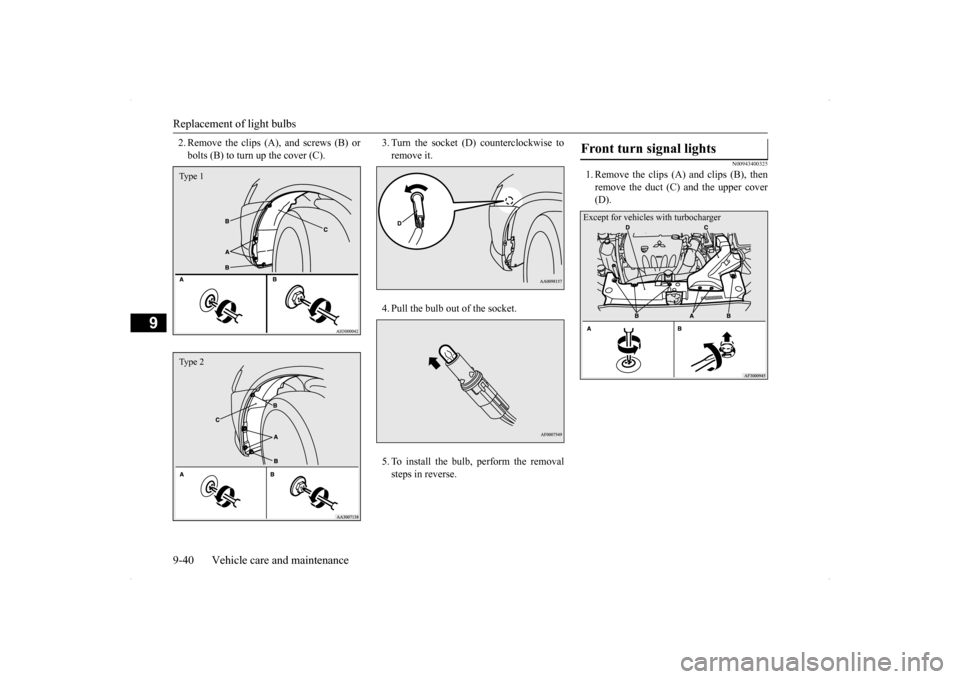
2. Remove the clips (A), and screws (B) or bolts (B) to turn up the cover (C).
3. Turn the socket (D) counterclockwise to remove it. 4. Pull the bulb out of the socket.5. To install the bulb, perform the removal steps in reverse.
N00943400325
1. Remove the clips (A) and clips (B), thenremove the duct (C) and the upper cover(D).
Type 1Type 2
Front turn signal lights Except for vehicles with turbocharger