turn signal MITSUBISHI LANCER 2014 8.G Owner's Manual
[x] Cancel search | Manufacturer: MITSUBISHI, Model Year: 2014, Model line: LANCER, Model: MITSUBISHI LANCER 2014 8.GPages: 434, PDF Size: 57.5 MB
Page 221 of 434
Headlight leveling switch (if so equipped) 5-154 Features and controls
5
3. Within 60 seconds of turning the ignition switch to the “LOCK” position, pull the turn signal lever toward you. 4. The headlights will come on in the low beam setting for about 30 seconds. Afterthe headlights go off, the headlights can be turned on again in the low beam setting for about 30 seconds by pulling the turnsignal lever toward you within 60 secondsof turning the ignition switch to the “LOCK” position. To turn on the head- lights again after 60 seconds of turningthe ignition switch to the “LOCK” posi- tion, repeat the process from step 1.
N00537100088
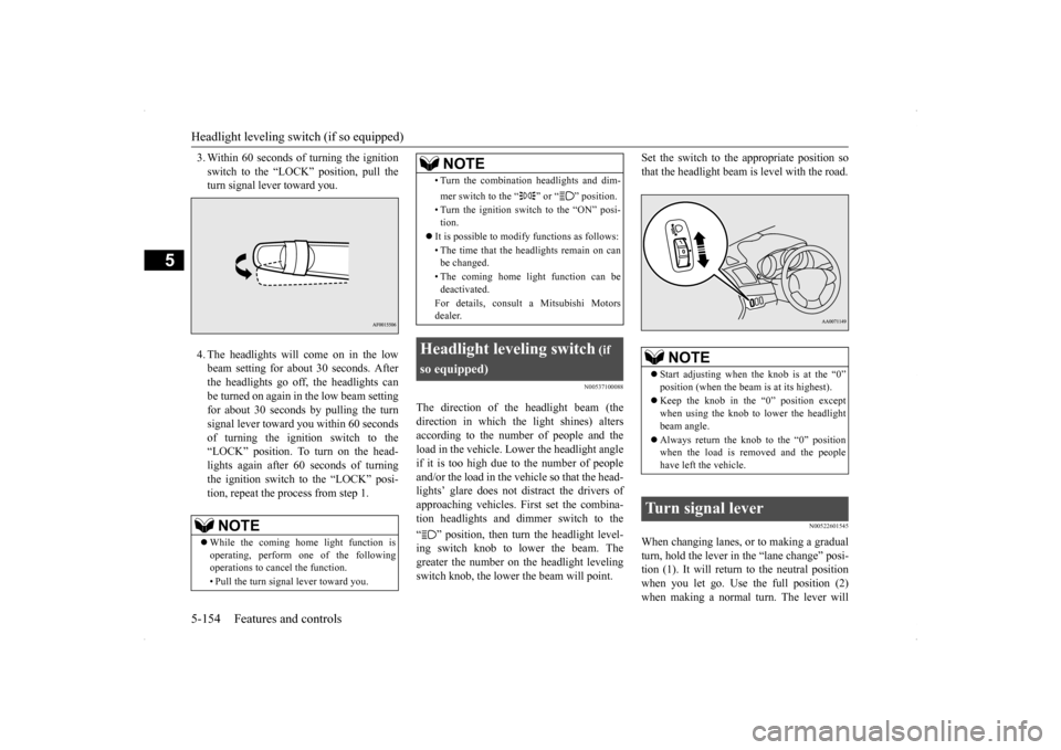
The direction of the headlight beam (the direction in which the light shines) alters according to the number of people and the load in the vehicle. Lower the headlight angleif it is too high due to the number of peopleand/or the load in the vehicle so that the head- lights’ glare does not distract the drivers of approaching vehicles. First set the combina-tion headlights and di
mmer switch to the
“ ” position, then turn the headlight level- ing switch knob to lower the beam. Thegreater the number on the headlight levelingswitch knob, the lower the beam will point.
Set the switch to the appropriate position so that the headlight beam is level with the road.
N00522601545
When changing lanes, or to making a gradual turn, hold the lever in the “lane change” posi- tion (1). It will return to the neutral positionwhen you let go. Use the full position (2) when making a normal turn. The lever will
NOTE
While the coming home light function is operating, perform one of the followingoperations to cancel the function. • Pull the turn signal lever toward you.
• Turn the combination headlights and dim- mer switch to the “ ” or “ ” position. • Turn the ignition switch to the “ON” posi- tion.
It is possible to modify functions as follows: • The time that the headlights remain on can be changed. • The coming home light function can be deactivated. For details, consult a Mitsubishi Motors dealer.
Headlight leveling switch
(if
so equipped)
NOTE
NOTE
Start adjusting when the knob is at the “0” position (when the beam is at its highest). Keep the knob in the “0” position except when using the knob to lower the headlightbeam angle. Always return the knob to the “0” position when the load is removed and the people have left the vehicle.
Turn signal lever
Page 222 of 434
Hazard warning flasher switch Features and controls 5-155
5
return to the neutral position when the turn is complete. There may be times when the lever does not return to the neutral position. This usually happens when the steering wheel isturned only slightly. You can easily return the lever by hand. Also, when you move the lever to (1) slightlythen release it, the turn signal lights and indi- cator light in the instrument cluster will flash three times.
N00522700217
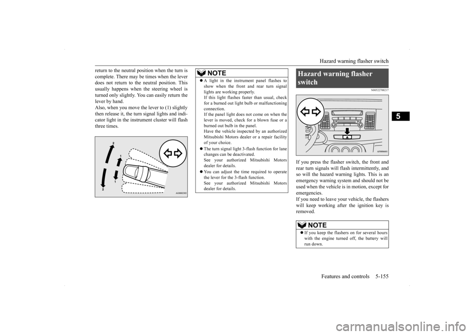
If you press the flasher switch, the front andrear turn signals will flash intermittently, and so will the hazard warning lights. This is an emergency warning system and should not beused when the vehicle is in motion, except foremergencies. If you need to leave your vehicle, the flashers will keep working afte
r the ignition key is
removed.
NOTE
A light in the instrument panel flashes to show when the front and rear turn signal lights are working properly. If this light flashes faster than usual, check for a burned out light bulb or malfunctioningconnection. If the panel light does not come on when the lever is moved, check for a blown fuse or aburned out bulb in the panel. Have the vehicle inspected by an authorized Mitsubishi Motors dealer or a repair facilityof your choice. The turn signal light 3-flash function for lane changes can be deactivated. See your authorized Mitsubishi Motors dealer for details. You can adjust the time required to operate the lever for the 3-flash function.See your authorized Mitsubishi Motors dealer for details.
Hazard warning flasher switch
NOTE
If you keep the flashers on for several hours with the engine turned off, the battery will run down.
Page 265 of 434
Safe driving techniques 6-4 Driving safety
6
Replace your tires before they are heavily worn out. As your vehicle is equipped with a tire pres- sure monitoring system, there is a risk ofdamage to the tire inflation pressure sensors when the tire is replaced on the rim. Tire replacement should, therefore, be performedonly by an authorized Mitsubishi Motors dealer. Have someone watch while you turn all the exterior lights on and off. Also check the turn signal indicators and high-beam indicators on the instrument panel. Check the ground under the vehicle after parking overnight, for fuel, water, oil, orother leaks. Make sure all the fluid levels are correct. Also, if you can smell fuel, you need to find out why immediately and have itfixed.
N00629200111
Even this vehicle’s safety equipment, andyour safest driving, cannot guarantee that you
can avoid an accident or injury. However, if you give extra attention to the following areas, you can better protect yourself and your passengers: Drive defensively. Be aware of traffic, road and weather conditions. Leave plenty of stopping distance between your vehicle and the vehicle ahead. Before changing lanes, check your mir- rors and use your turn signal light. While driving, watch the behavior of other drivers, bicyclists, and pedestrians. Always obey applicable laws and regula- tions. Be a polite and alert driver. Always leave room for unexpected events, such assudden braking. If you plan to drive in another country, obey their vehicle registration laws andmake sure you will be able to get the right fuel.
N00629400429
Check the battery, including terminals and cables. During extremely cold weather,the battery will not be as strong. Also, the battery power level may drop because more power is used for cold starting anddriving. Before driving the vehicle, check to see if the engine runs at the proper speed and ifthe headlights are as bright as normally.Charge or replace the battery if necessary. During extreme cold weather, it is possi- ble that a very low battery could freeze. Warm the engine sufficiently. After start- ing the engine, allow a short warm-up time to distribute oil
to all cylinders and
turbocharger. Then drive your vehicleslowly.
Lights Fluid leaks Safe driving techniques
Driving during cold weather
WA R N I N G The battery gives off explosive hydrogen gas. Any spark or flame can cause the bat-tery to explode, which could cause serious injury or death. Always wear protective clothes and a facemask when working with your battery, or let a skilled mechanic do it.
Page 317 of 434
Listen to Radio 7-42 Comfort controls
7
N00716900027
This explains how to listen to AM and FM radio broadcasts. Press the RADIO key to switch the band. Switch between AM and FM bands. The selected band is indicated on the display. *: When a satellite tuner is connected Turn the /SEL key to the frequency to lis- ten to.
Collective search for stations that can be received. Press the SCAN key.When a station is received, this is played for 5 seconds, then the product searches for the next station.
Register the broadcast station in advance, and select this at a later time. 1. Tune in to the frequency to register. 2. Hold down any of the keys from the 1RPT key to the 6 key. A “Beep” sounds, and the preset key is registered.
During RBDS broadcast reception, select PTY (program content), and automatically scan for stations. 1. During FM reception, press the PTY key. This switches to the PTY selection mode. 2. Press the PTY key to select PTY.
*2: Requires a separately-purchased Blue- tooth-capable audio device (vehicles with a Bluetooth
® 2.0 interface).
*3: Requires a satellite tuner connection.
Listen to Radio To Listen to the Radio
NOTE
Bands switch in the order AM, FM1, FM2, SIR1*, SIR2*, SIR3*, and SIR4*. If no signal is received, bands will not be switched to SIR2, SIR3, or SIR4.
Manual/Seek Station Selection
/SEL key (counter- clockwise)
Reduces the frequency being received.
/SEL key (clockwise)
Increases the frequency being received.
key
(hold down)
Release the button to start seek station selection, and when a station is received, scanning stops.
key
(hold down)Scan Station Selection
NOTE
Press this button again while receiving the station to return to normal reception.
Preset Memory
NOTE
The preset memory can register a maximum of 6 stations for each band. If a preset key that already has a station reg- istered is selected, then this is overwritten with the new preset. Pressing the preset key will select the previ- ously registered frequency.
PTY Search
Page 318 of 434
Listen to Satellite Radio (if so equipped)
Comfort controls 7-43
7
3. Press the key or key. The PTY (program content) indicator willflash, and station selection will automati- cally start. When a station is received, the frequencyis displayed.
During RBDS broadcast reception, select PTY (program content) to perform a collec-tive search for stations. 1. During FM reception, press the PTY key. This switches to the PTY selection mode. 2. Press the PTY key to select PTY. 3. Press the SCAN key.When a broadcast station is received, this is played for 5 seconds, then the product searches for the next station.
N00717000025
This section explains ho
w to listen to satellite
radio. Press the RADIO key to switch the band. Switches between SIR1, SIR2, SIR3, and SIR4 bands. The selected band is indicated on the display.
Press the key or key to select the sta- tion.
NOTE
This receives the station detected first. 10 seconds after reception, PTY search mode will be cancelled. To receive a different station, press the key or key again.
PTY Scan
NOTE
Press this key again while receiving the sta- tion to return to normal reception.
Listen to Satellite Radio
(if so
equipped)
NOTE
A subscription is required to listen to satel- lite radio. Satellite radio cannot be receivedafter the free trial period has expired. If no subscription has been made when the free trial period expires, the display will alternate between “CALL” and “888-539- SIRI”.
To listen to Satellite Radio
NOTE
Bands switch in the order AM, FM1, FM2, SIR1, SIR2*, SIR3*, and SIR4*. Switch satellite radio bands by holding down the key or key on the steering remote control switch.*:If no signal is received, bands will not be switched.
Select a Station
key
Go down one step from the channel being received.
key
Go up one step from the channel being received.
key
(Hold down)
While the key is held down, it will cycle down through the channels being received.
key
(Hold down)
While the key is held down, it will cycle up through the channels being received.
Page 338 of 434
General information about your radio
Comfort controls 7-63
7
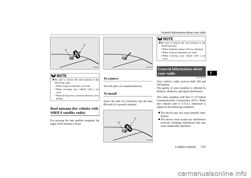
For securing the best satellite reception, the angle of the antenna is fixed.
Turn the pole (A) counterclockwise. Screw the pole (A) clockwise into the base (B) until it is securely retained.
N00733901478
Your vehicle’s radio receives both AM andFM stations.The quality of your reception is affected by distance, obstacles, and signal interference. This radio complies with Part 15 of Federal Communications Commission (FCC) Rules(for vehicles sold in U.S.A.). Operation is subject to the following conditions: The device may not cause harmful inter- ference. This device must accept any interference recieved, including interference that may cause undesirable operation.
NOTE
Be sure to remove the roof antenna in the following cases: • When using an automatic car wash• When covering your vehicle with a car cover • When driving into a structure that has a low ceiling
Roof antenna (for vehicles with SIRIUS satellite radio)
To remove To install
NOTE
Be sure to remove the roof antenna in the following cases: • When entering a place with low clearance • When using an automatic car wash • When covering your vehicle with a car cover
General information about your radio
Page 348 of 434
How to change a tire
For emergencies 8-7
8
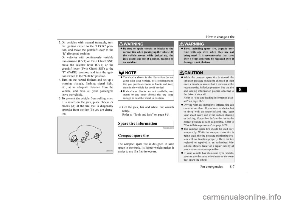
3. On vehicles with manual transaxle, turn the ignition switch to the “LOCK” posi- tion, and move the gearshift lever to the “R” (Reverse) position.On vehicles with continuously variable transmission (CVT) or Twin Clutch SST, move the selector lever (CVT) or thegearshift lever (Twin Clutch SST) to the “P” (PARK) position, and turn the igni- tion switch to the “LOCK” position.4. Turn on the hazard flashers and set up awarning triangle, flashing signal light, etc., at an adequate distance from the vehicle, and have all your passengersleave the vehicle. 5. To prevent the vehicle from rolling when it is raised on the jack, place chocks orblocks (A) at the tire that is diagonally opposite from the tire (B) you are chang- ing.
6. Get the jack, bar and wheel nut wrench ready.Refer to “Tools and jack” on page 8-5.
N00849600298
The compact spare tire is designed to savespace in the trunk. Its lighter weight makes it easier to use if a flat tire occurs.
WA R N I N G Be sure to apply chocks or blocks to the correct tire when jacking up the vehicle. If the vehicle moves while jacked up, the jack could slip out of position, leading to an accident.NOTE
The chocks shown in the illustration do not come with your vehicle. It is recommended that you purchase chocks or blocks and keepthem in the vehicle for use if needed. If chocks or blocks are not available, use stones or any other objects that are large enough to hold the wheel in position.
Spare tire information Compact spare tire
WA R N I N G Tires, including spare tire, degrade over time with age even when they are not being used. It is recommended that tires over 6 years generally be replaced even if damage is not obvious.CAUTION While the compact spare tire is stowed, the inflation pressure should be checked at least once a month to assure that it remains at therecommended inflation pressure. See the tire and loading information placard attached to the driver’s door sill.Refer to “Tire and loading information plac- ard” on page 11-3. Driving with an improperly inflated tire can cause an accident. If you have no choice but to drive with an under-inflated tire, keepyour speed down and avoid sudden steering or braking, if possible. Inflate the tire to the correct pressure as soon as possible. Refer to“Tire inflation pressures” on page 9-21. The compact spare tire should be used only temporarily. While the compact spare tire is being used, the tire pressure monitoring sys- tem will not function properly. Have the tire replaced or repaired at an authorized Mit- subishi Motors dealer or a repair facility ofyour choice as soon as possible. If your vehicle has aluminum type wheels, you can use the same wheel nuts on the com- pact spare tire wheel.
Page 393 of 434
Replacement of light bulbs 9-34 Vehicle care and maintenance
9
N00943000099
The bulb should only be replaced with a new bulb with the same ra
ting and type. The type
and rating are listed on the base of the bulb.
N00950300805
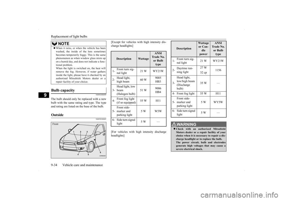
[Except for vehicles with high intensity dis-charge headlights] [For vehicles with high intensity discharge headlights]
When it rains, or when the vehicle has been washed, the inside of the lens sometimes becomes temporarily foggy. This is the same phenomenon as when window glass mists up on a humid day, and does not indicate a func-tional problem. When the light is switched on, the heat will remove the fog. However, if water gathersinside the light, please have it checked by an authorized Mitsubishi Motors dealer or a repair facility of your choice.
Bulb capacity Outside
NOTE
Front
Description
Wattage
ANSI Trade No. or Bulb type
1-
Front turn sig- nal light
21 W WY21W
2-
Head light, high beam
60 W
9005 HB3
3-
Head light, low beam (Halogen bulb)
51 W
9006 HB4
4-
Front fog light (if so equipped)
55 W H11
5-
Front side- marker and parking light
5 W W5W
6- Side turn signal
light
5 W —
Description
Wattage or Can- dle power
ANSI Trade No. or Bulb type
1-
Front turn sig- nal light
21 W WY21W
2-
Daytime run- ning light
27 W
1156
32 cp
3-
Head light, low/high beam (Discharge bulb)
35 W —
4- Front fog light 55 W H11 5-
Front side- marker and parking light
5 W WY5W
6- Side turn signal
light
5 W —
WA R N I N G Check with an authorized Mitsubishi Motors dealer or a repair facility of yourchoice when it is necessary to repair a dis- charge headlight or to replace the bulb. The power circuit, bulb and electrodesgenerate high voltages that may cause a severe electrical shock.
Page 394 of 434
Replacement of light bulbs
Vehicle care and maintenance 9-35
9
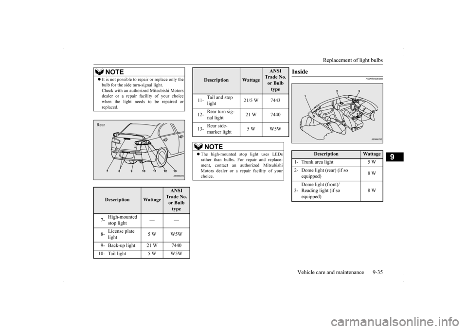
N00950400460
NOTE
It is not possible to re
pair or replace only the
bulb for the side turn-signal light. Check with an authorized Mitsubishi Motors dealer or a repair
facility of your choice
when the light needs to be repaired orreplaced.Description
Wattage
ANSI Trade No. or Bulb type
7-
High-mounted stop light
——
8-
License plate light
5 W W5W
9- Back-up light 21 W 7440 10- Tail light 5 W W5WRear
11-
Tail and stop light
21/5 W 7443
12-
Rear turn sig- nal light
21 W 7440
13-
Rear side- marker light
5 W W5W
NOTE
The high-mounted stop light uses LEDs rather than bulbs. For repair and replace- ment, contact an authorized Mitsubishi Motors dealer or a repair facility of yourchoice.Description
Wattage
ANSI Trade No. or Bulb type
Inside
Description
Wattage
1- Trunk area light 5 W2- Dome light (rear) (if so
equipped)
8 W
3-
Dome light (front)/ Reading light (if so equipped)
8 W
Page 399 of 434
Replacement of light bulbs 9-40 Vehicle care and maintenance
9
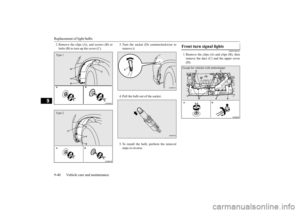
2. Remove the clips (A), and screws (B) or bolts (B) to turn up the cover (C).
3. Turn the socket (D) counterclockwise to remove it. 4. Pull the bulb out of the socket.5. To install the bulb, perform the removal steps in reverse.
N00943400325
1. Remove the clips (A) and clips (B), thenremove the duct (C) and the upper cover(D).
Type 1Type 2
Front turn signal lights Except for vehicles with turbocharger