stop start MITSUBISHI LANCER 2014 8.G Owners Manual
[x] Cancel search | Manufacturer: MITSUBISHI, Model Year: 2014, Model line: LANCER, Model: MITSUBISHI LANCER 2014 8.GPages: 434, PDF Size: 57.5 MB
Page 40 of 434
Seat belts
Seat and restraint systems 4-11
4
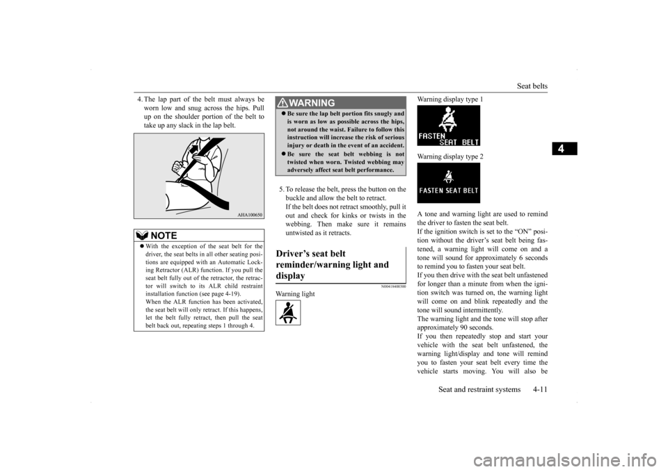
4. The lap part of the belt must always be worn low and snug across the hips. Pull up on the shoulder portion of the belt to take up any slack in the lap belt.
5. To release the belt, press the button on the buckle and allow the belt to retract. If the belt does not retract smoothly, pull itout and check for kinks or twists in the webbing. Then make sure it remains untwisted as it retracts.
N00418400300
Warning light
Warning display type 1 Warning display type 2 A tone and warning light are used to remind the driver to fasten the seat belt.If the ignition switch is set to the “ON” posi- tion without the driver’s seat belt being fas- tened, a warning light will come on and atone will sound for approximately 6 seconds to remind you to fasten your seat belt. If you then drive with
the seat belt unfastened
for longer than a minute from when the igni- tion switch was turned on, the warning light will come on and blink repeatedly and thetone will sound intermittently.The warning light and the tone will stop after approximately 90 seconds. If you then repeatedly stop and start yourvehicle with the seat belt unfastened, the warning light/display and tone will remind you to fasten your seat belt every time thevehicle starts moving. You will also be
NOTE
With the exception of the seat belt for the driver, the seat belts in all other seating posi- tions are equipped with an Automatic Lock- ing Retractor (ALR) function. If you pull theseat belt fully out of the retractor, the retrac- tor will switch to its ALR child restraint installation function (see page 4-19).When the ALR function has been activated, the seat belt will only retract. If this happens, let the belt fully retract, then pull the seatbelt back out, repeating steps 1 through 4.
WA R N I N G Be sure the lap belt portion fits snugly and is worn as low as possible across the hips, not around the waist. Failure to follow this instruction will increase the risk of serious injury or death in the
event of an accident.
Be sure the seat belt webbing is not twisted when worn. Twisted webbing mayadversely affect seat belt performance.
Driver’s seat belt reminder/warning light and display
Page 68 of 434
5
Features and controlsBreak-in recommendation
s ...............................................................5-3
Keys .....................................................
.............................................5-3
Electronic immobilizer (Anti-theft starting system) .........................5-4 Keyless entry system (if so equipped) ..............................................5-7Free-hand Advanced Security Transmitter (F.A.S.T.-key) (if so equipped)................................
.....................................................5-12
Door locks........................
...............................................................5-36
Power door locks .............
...............................................................5-38
“Child safety locks” for
rear door...................................................5-40
Trunk lid ....................................
.....................................................5-40
Inside emergency trunk lid
release .................................................5-42
Theft-alarm system ..........
...............................................................5-42
Power windows................
...............................................................5-45
Sunroof (if so equipped
) .........................................
........................5-47
Parking brake ...................
...............................................................5-49
Steering wheel tilt lock lever ..........................................................5-51Inside day/night rearview
mirror ....................................................5-51
Outside rearview mirr
ors ................................................................5-53
Ignition switch .................
...............................................................5-54
Steering wheel lock..........
...............................................................5-56
Starting and stopping the e
ngine ....................................................5-56
Turbocharger operation (if so equipped) ........................................5-60Manual transaxle (if so equipped) ..................................................5-60Continuously variable transmissi
on (CVT) (if so equipped)..........5-62
Twin Clutch SST (Sportronic Shif
t Transmission) (if so equipped)
...................................................................
..................................5-71
ACD (Active center differential system) (if so equipped)..............5-83 Electronically controlled 4WD system (if so equipped).................5-85
All-wheel driving opera
tion ........................................................... 5-87
Cautions on handling of all-wheel drive vehicles ......................... 5-89 Limited-slip differential (i
f so equipped) ....................................... 5-90
Service brake ..................
.................................................
............... 5-90
Brake assist system
................................................
......................... 5-91
Hill start assist (vehicles with
Twin Clutch SST) ........................... 5-91
Anti-lock braking syst
em ......................................
......................... 5-92
Active Stability Control (ASC
) (if so equipped) ............................ 5-95
Power steering system
...........................................
......................... 5-98
Cruise control (if so eq
uipped) ....................................................... 5-99
Tire pressure monitoring
system .................................................. 5-104
Rear-view camera (if so
equipped)..............
................................. 5-108
Instrument cluster ..........
.............................................................. 5-110
Multi-information display ............................................................ 5-112 Indicator light, warning light, and information screen display list
.................................................................
................................. 5-133
Indicators ..................................
.................................................... 5-145
Warning lights.................
.................................................
............. 5-146
Information screen disp
lay ....................................
....................... 5-147
Combination headlights and dimmer switch ................................ 5-149 Headlight leveling switch (if
so equipped)................................... 5-154
Turn signal lever ...
.................................................
....................... 5-154
Hazard warning flasher
switch ..................................................... 5-155
Front fog light switch (if so
equipped) ......................................... 5-156
Wiper and washer swit
ch ......................................
....................... 5-156
Electric rear window def
ogger switch .......................................... 5-160
Horn switch ..............................
.................................................... 5-161
Link System (if so equi
pped) ....................................................... 5-161
Page 84 of 434
Free-hand Advanced Security Transmit
ter (F.A.S.T.-key) (if so equipped)
Features and controls 5-17
5
N00513600021
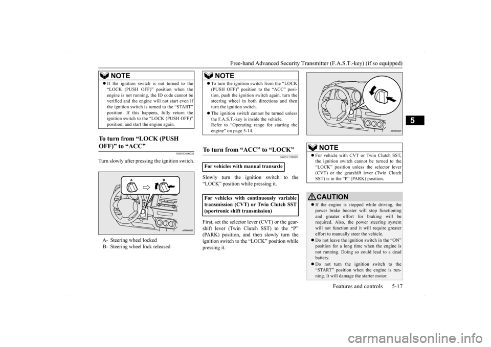
Turn slowly after pressing the ignition switch.
N00513700051
Slowly turn the ignition switch to the “LOCK” position while pressing it. First, set the selector lever (CVT) or the gear- shift lever (Twin Clutch SST) to the “P” (PARK) position, and then slowly turn the ignition switch to the “LOCK” position whilepressing it.
If the ignition switch is not turned to the “LOCK (PUSH OFF)” position when the engine is not running, the ID code cannot be verified and the engine will not start even if the ignition switch is turned to the “START”position. If this happens, fully return the ignition switch to the “LOCK (PUSH OFF)” position, and start the engine again.
To turn from “LOCK (PUSH OFF)” to “ACC”
A- Steering wheel locked B- Steering wheel lock released
NOTE
NOTE
To turn the ignition switch from the “LOCK (PUSH OFF)” position to the “ACC” posi- tion, push the ignition switch again, turn the steering wheel in both directions and then turn the ignition switch. The ignition switch cannot be turned unless the F.A.S.T.-key is inside the vehicle.Refer to “Operating range for starting the engine” on page 5-14.
To turn from “ACC” to “LOCK”
For vehicles with manual transaxle For vehicles with continuously variable transmission (CVT) or Twin Clutch SST(sportronic shift transmission)
NOTE
For vehicle with CVT or Twin Clutch SST, the ignition switch cannot be turned to the “LOCK” position unless the selector lever (CVT) or the gearshift lever (Twin ClutchSST) is in the “P” (PARK) position.CAUTION If the engine is stopped while driving, the power brake booster will stop functioningand greater effort for braking will be required. Also, the power steering system will not function and it will require greatereffort to manually steer the vehicle. Do not leave the ignition switch in the “ON” position for a long time when the engine is not running. Doing so could lead to a dead battery. Do not turn the ignition switch to the “START” position when the engine is run-ning. It will damage the starter motor.
Page 92 of 434
Free-hand Advanced Security Transmit
ter (F.A.S.T.-key) (if so equipped)
Features and controls 5-25
5
2. Install the cover of the ignition switch. 3. Reinsert the emergency key into theF. A . S . T. - k e y.
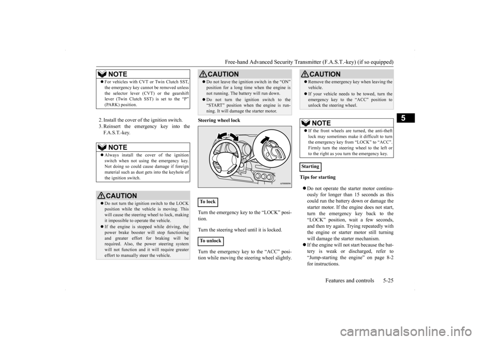
Steering wheel lock Turn the emergency key to the “LOCK” posi- tion. Turn the steering wheel until it is locked. Turn the emergency key to the “ACC” posi- tion while moving the steering wheel slightly.
Tips for starting Do not operate the starter motor continu- ously for longer than 15 seconds as this could run the battery down or damage the starter motor. If the engine does not start,turn the emergency key back to the “LOCK” position, wait a few seconds, and then try again. Trying repeatedly withthe engine or starter motor still turning will damage the starter mechanism. If the engine will not start because the bat- tery is weak or discharged, refer to “Jump-starting the engine” on page 8-2 for instructions.
NOTE
For vehicles with CVT or Twin Clutch SST, the emergency key cannot be removed unless the selector lever (CVT) or the gearshift lever (Twin Clutch SST) is set to the “P” (PARK) position.NOTE
Always install the cover of the ignition switch when not using the emergency key. Not doing so could cause damage if foreignmaterial such as dust
gets into the keyhole of
the ignition switch.CAUTION Do not turn the ignition switch to the LOCK position while the vehicle is moving. This will cause the steering wheel to lock, making it impossible to operate the vehicle. If the engine is stopped while driving, the power brake booster will stop functioning and greater effort for braking will be required. Also, the power steering systemwill not function and it will require greater effort to manually steer the vehicle.
Do not leave the ignition switch in the “ON” position for a long time when the engine is not running. The battery will run down. Do not turn the ignition switch to the “START” position when the engine is run- ning. It will damage the starter motor.
To l o c k To u n l o c k
CAUTION
CAUTION Remove the emergency key when leaving the vehicle. If your vehicle needs to be towed, turn the emergency key to the “ACC” position tounlock the steering wheel.NOTE
If the front wheels are turned, the anti-theft lock may sometimes make it difficult to turnthe emergency key from “LOCK” to “ACC”. Firmly turn the steering wheel to the left or to the right as you turn the emergency key.
Starting
Page 123 of 434
![MITSUBISHI LANCER 2014 8.G Owners Manual Steering wheel lock 5-56 Features and controls
5
N00512500195
[For vehicles equipped with the F.A.S.T.-key] For information on operations for vehiclesequipped with the F.A.S.T.-key, refer to “F.A.S. MITSUBISHI LANCER 2014 8.G Owners Manual Steering wheel lock 5-56 Features and controls
5
N00512500195
[For vehicles equipped with the F.A.S.T.-key] For information on operations for vehiclesequipped with the F.A.S.T.-key, refer to “F.A.S.](/img/19/7460/w960_7460-122.png)
Steering wheel lock 5-56 Features and controls
5
N00512500195
[For vehicles equipped with the F.A.S.T.-key] For information on operations for vehiclesequipped with the F.A.S.T.-key, refer to “F.A.S.T.-key: Steering wheel lock” on page 5-20. [Except for vehicles equipped with the F. A . S . T. - k e y ]
Remove the key at the “LOCK” position. Turn the steering wheel until it is locked. Turn the key to the “ACC” position while moving the steering wheel slightly.
N00542100060
Do not operate the starter motor continu- ously for longer than 15 seconds as thiscould run the battery down or damage the starter motor. If the engine does not start, turn the ignition switch back to the“LOCK” position, wait a few seconds, and then try again. Trying repeatedly with the engine or starter motor still turningwill damage the starter mechanism. If the engine will not start because the bat- tery is weak or discharged, refer to“Jump-starting the engine” (on page 8-2) for instructions.
If the engine is turned off while driving, the power brake booster will stop functioning and braking efficiency will be reduced. Also, the power steering system will not function and it will require greater effort to manuallysteer the vehicle. Do not leave the key in the “ON” position for a long time when the engine is not running. This will cause the battery to run down. Do not turn the key to the “START” position when the engine is running. It will damage the starter motor.
Steering wheel lock
CAUTION
To l o c k To u n l o c k
CAUTION Remove the key when leaving the vehicle.
NOTE
If the front wheels are turned, the anti-theft lock may sometimes make it difficult to turn the key from “LOCK” position to “ACC” position. Firmly turn the steering wheel to the left or to the right as you turn the key.
Starting and stopping the engine Tips for starting
Page 124 of 434
![MITSUBISHI LANCER 2014 8.G Owners Manual Starting and stopping the engine Features and controls 5-57
5
[Except for vehicles equipped with the turbocharger] The engine is warmed up enough for driv- ing when the bar graph of engine coolant MITSUBISHI LANCER 2014 8.G Owners Manual Starting and stopping the engine Features and controls 5-57
5
[Except for vehicles equipped with the turbocharger] The engine is warmed up enough for driv- ing when the bar graph of engine coolant](/img/19/7460/w960_7460-123.png)
Starting and stopping the engine Features and controls 5-57
5
[Except for vehicles equipped with the turbocharger] The engine is warmed up enough for driv- ing when the bar graph of engine coolanttemperature display starts to move. A lon- ger warm up period will only consume extra fuel. [For vehicles equipped with the turbo- charger] The engine is warmed up enough for driv-ing when the bar graph of engine coolanttemperature display starts to move. Driv- ing before the bar graph moves may cause deterioration of turbocharger performanceand driveability. A longer warm up period will only consume extra fuel. On vehicles equipped with the Twin Clutch SST, the following may occur after the engine is started, but they do not indi- cate an abnormality.• You may hear operational sounds of the Twin Clutch SST and you may feel vibration in the vehicle body.• If you shift the gearshift lever into the “N” (NEUTRAL) position and depress the accelerator pedal, increases in theengine speed will be limited.
N00542200146
[For vehicles equipped with the F.A.S.T.-key.]For information on operation for vehicles equipped with the F.A.S.T.-key, refer to “F.A.S.T.-key: Starting the engine” on page5-20. [Except for vehicles equipped with the F. A . S . T. - k e y. ]Your vehicle is equipped with an electroni- cally controlled fuel injection system, which automatically controls the release of fuel.
There is usually no need to depress the accel- erator pedal when starting the engine. The starter should not be run for more than 15 seconds at a time.To prevent battery drain, wait a few seconds between attempts to restart the engine. 1. Make sure all occupants are properly seated with seat belts fastened 2. Insert the ignition key. 3. Make sure the parking brake is applied.4. Press and hold the brake pedal down withyour right foot. 5. Press and hold the clutch pedal all the way down (manual transaxle).
WA R N I N G Never run the engine in a closed or poorly ventilated area any longer than is needed to move your vehicle out of the area. Car- bon monoxide gas, which is odorless and extremely poisonous, could build up andcause serious injury or death.CAUTION Do not push-start the vehicle.Do not run the engine
at high rpms or drive
at high speeds until the engine has had a chance to warm up. Release the ignition switch as soon as the engine starts. Otherwise, the starter motorwill be damaged.
Starting the engine
NOTE
For models equipped with a manual trans- axle, the starter will not operate unless the clutch pedal is fully depressed (Clutch inter-lock). This is a safety feature.
Page 125 of 434

Starting and stopping the engine 5-58 Features and controls
5
6. On vehicles with manual transaxle, place the gearshift lever in the “N” (Neutral) position. On vehicles with continuously variabletransmission (CVT) or Twin Clutch SST, make sure the selector lever (CVT) or gearshift lever (Twin Clutch SST) is in the“P” (PARK) position. 7. Turn the ignition switch to the “ON” posi- tion and make certain that all warning lights are functioning properly beforestarting the engine. 8. Turn the ignition switch to the “START” position without pressing the acceleratorpedal. Release the key when the engine starts.
After several attempts, you may experience that the engine still does not start. 1. Make sure that all electric devices, such as lights, air conditioning blower and rear window defogger, are turned off. 2. While depressing the brake pedal on vehi-cles equipped with continuously variable transmission (CVT) or Twin Clutch SST or the clutch pedal on the vehiclesequipped with manual transaxle, press the accelerator pedal halfway and hold it there, then crank the engine. Release theaccelerator pedal, immediately after the engine starts.
3. If the engine still will not start, the engine could be flooded with too much gasoline. While depressing the brake pedal on vehi- cles equipped with CVT or Twin ClutchSST or the clutch pedal on the vehicles equipped with manual transaxle, push the accelerator pedal all the way down andhold it there, then crank the engine for 5 to 6 seconds. Return the ignition switch to the “LOCK” position and release theaccelerator pedal. Wait a few seconds, andthen crank the engine again for 5 to 6 sec- onds while depressing the brake pedal or the clutch pedal, but do not push theaccelerator pedal. Release the ignition key if the engine starts. If the engine fails to start, repeat these procedures. If theengine still will not start, contact your local Mitsubishi Motors dealer or a repair facility of your choice for assistance.
When the ambient temperature is -4 °F (-20 °C) or lower on vehicles with CVT, or -22 °F (-30 °C) or lower on vehicles with TwinClutch SST, it may not be possible to start
NOTE
On vehicles with CVT, the starter will not operate unless the selector lever is in the “P”(PARK) or “N” (NEUTRAL) position. On vehicles with Twin Clutch SST, the starter will not operate unless the gearshiftlever is in the “P” (PARK) position or the gearshift lever is in the “N” (NEUTRAL) position with the brake pedal depressed.For safety reasons, start the engine in the “P” (PARK) position so that the wheels are locked.
NOTE
Minor noises may be heard on engine start- up. These will disappear as the engine warms up.
When the engine is hard to start
Startability of continuously vari- able transmission (CVT) vehicles or Twin Clutch SST vehicles at extremely cold ambient tempera- ture
Page 126 of 434

Starting and stopping the engine Features and controls 5-59
5
from a standstill even with the selector lever (CVT) or the gearshift lever (Twin Clutch SST) in the “D” (DRIVE) position. This phenomenon occurs because the trans-axle has not warmed up sufficiently; it does not indicate a problem. If it occurs, place the selector lever (CVT) or the gearshift lever(Twin Clutch SST) in the “P” (PARK) posi- tion and let the engine idle for at least 10 min- utes.The transaxle will warm up, and you will beable to start normally. Do not leave the vehicle during warm-up operation.
N00547600015
At high altitude locations, the idle speed maybe higher. This is done in order to stabilizethe idle speed when the power steering sys- tem and other systems operate. It does not indicate a malfunction.
N00542300088
1. Bring the vehicle to a complete stop. 2. Fully engage the parking brake whiledepressing the brake pedal.
3. For vehicles with a manual transaxle, turn the ignition switch to the “LOCK” posi- tion to stop the engine, and then move the gearshift lever to the 1st (on a uphill) or“R” (Reverse) (on a downhill) position. For vehicles with continuously variable transmission (CVT) or Twin Clutch SST,place the selector lever (CVT) or the gear- shift lever (Twin Clutch SST) in the “P” (PARK) position, and then turn the igni-tion switch to the “LOCK” position tostop the engine.
Idle speed in high altitude area Stopping the engine
NOTE
For vehicles with Twin Clutch SST, the engine will stop and the vehicle power will turn off approximately 1 second after the ignition switch is turned to the “LOCK”; position. The reason for this is that, in the time from when the ignition switch is turned to the“LOCK” position until the engine stops, the gears inside the Twin Clutch SST disengage so that the engine will start smoothly thenext time it is started. Two clutches installed in the Twin Clutch SST alternately engage and disengage toachieve smooth shifting. In addition, the gear on the side with the free clutch is engaged, therefore, quick shifting isperformed. If the engine was stopped with the gear engaged like this, it would provide resistancethe next time the engine is started. Therefore, the gear disengages in the approximately 1- second period until the engine stops. For vehicles with Twin Clutch SST, do not operate the gearshift lever or the acceleratorpedal for approximately 1 second until the engine stops.
Page 127 of 434
Turbocharger operation (if so equipped) 5-60 Features and controls
5
N00537300051
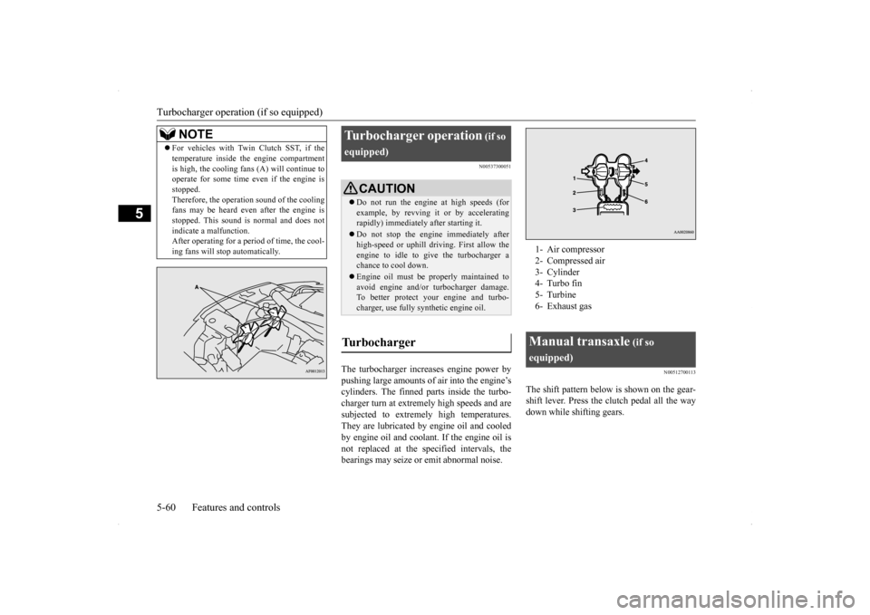
The turbocharger increases engine power by pushing large amounts of air into the engine’s cylinders. The finned parts inside the turbo-charger turn at extremely high speeds and are subjected to extremely high temperatures. They are lubricated by
engine oil and cooled
by engine oil and coolan
t. If the engine oil is
not replaced at the specified intervals, the bearings may seize or emit abnormal noise.
N00512700113
The shift pattern below is shown on the gear-shift lever. Press the clutch pedal all the waydown while shifting gears.
For vehicles with Twin Clutch SST, if the temperature inside the engine compartment is high, the cooling fans (A) will continue to operate for some time even if the engine is stopped.Therefore, the operation sound of the cooling fans may be heard even after the engine is stopped. This sound is normal and does notindicate a malfunction. After operating for a period of time, the cool- ing fans will stop automatically.NOTE
Turbocharger operation
(if so
equipped)
CAUTION Do not run the engine at high speeds (for example, by revving it or by acceleratingrapidly) immediately after starting it. Do not stop the engine immediately after high-speed or uphill driving. First allow the engine to idle to give the turbocharger a chance to cool down. Engine oil must be properly maintained to avoid engine and/or turbocharger damage.To better protect your engine and turbo- charger, use fully synthetic engine oil.
Turbocharger
1- Air compressor 2- Compressed air3- Cylinder 4- Turbo fin 5- Turbine6- Exhaust gasManual transaxle
(if so
equipped)
Page 133 of 434
Continuously variable transm
ission (CVT) (if so equipped)
5-66 Features and controls
5
N00514000194
Ty p e 1
or
Ty p e 2
or
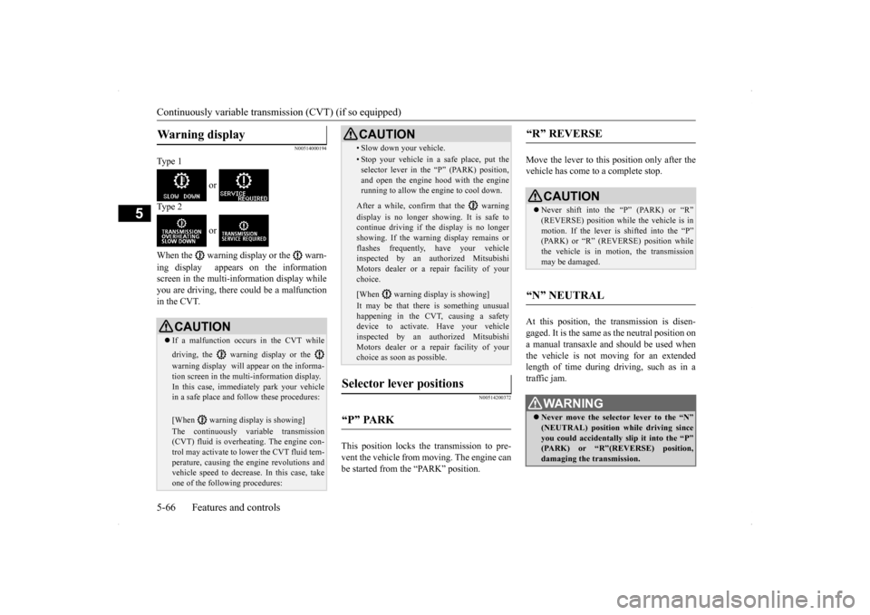
When the warning display or the warn- ing display appears on the information screen in the multi-information display whileyou are driving, there could be a malfunctionin the CVT.
N00514200372
This position locks the transmission to pre-vent the vehicle from moving. The engine canbe started from the “PARK” position.
Move the lever to this position only after the vehicle has come to a complete stop. At this position, the transmission is disen- gaged. It is the same as the neutral position ona manual transaxle and should be used when the vehicle is not moving for an extended length of time during driving, such as in atraffic jam.
Warning display
CAUTION If a malfunction occurs in the CVT while driving, the warning display or the warning display will appear on the informa- tion screen in the multi-information display. In this case, immediately park your vehiclein a safe place and follow these procedures: [When warning display is showing] The continuously variable transmission (CVT) fluid is overheating. The engine con- trol may activate to lower the CVT fluid tem- perature, causing the engine revolutions andvehicle speed to decrease. In this case, take one of the following procedures:
• Slow down your vehicle.• Stop your vehicle in a safe place, put theselector lever in the “P” (PARK) position, and open the engine hood with the enginerunning to allow the engine to cool down.After a while, confirm that the warning display is no longer showing. It is safe to continue driving if the display is no longershowing. If the warning display remains or flashes frequently, have your vehicle inspected by an authorized MitsubishiMotors dealer or a repair facility of your choice. [When warning display is showing] It may be that there is something unusual happening in the CVT, causing a safety device to activate. Have your vehicleinspected by an authorized Mitsubishi Motors dealer or a repair facility of your choice as soon as possible.
Selector lever positions
“P” PARK
CAUTION
“R” REVERSE
CAUTION Never shift into the “P” (PARK) or “R” (REVERSE) position whil
e the vehicle is in
motion. If the lever is shifted into the “P” (PARK) or “R” (REVERSE) position while the vehicle is in motion, the transmissionmay be damaged.
“N” NEUTRAL
WA R N I N G Never move the selector lever to the “N” (NEUTRAL) position while driving since you could accidentally slip it into the “P”(PARK) or “R”(REVERSE) position, damaging the transmission.