Ignition MITSUBISHI LANCER 2015 8.G Owners Manual
[x] Cancel search | Manufacturer: MITSUBISHI, Model Year: 2015, Model line: LANCER, Model: MITSUBISHI LANCER 2015 8.GPages: 434, PDF Size: 16.59 MB
Page 384 of 434
General maintenance
Vehicle care and maintenance 9-27
9
high heat sources such as the exhaust mani- fold.
N00941400116
If the fuel-vapor vent line is clogged or dam- aged, the fuel-vapor mixture will escape, pol- luting the air.Have the system checked at an authorized Mitsubishi Motors dealer at the mileage spec- ified in the “WARRANTY AND MAINTE-NANCE MANUAL”.
N00941500159
The next pages list the maintenance servicerecommended by Mitsubishi Motors Corpo- ration. In addition to the general maintenance that needs to be perfor
med at the times listed,
there are other parts which do not usually need regular maintenance. But, if any of these parts stops working prop- erly, your vehicle performance could suffer.Have these items checked if you notice a problem with them. See your authorized Mitsubishi Motors dealer for assistance, if you have any questions.
N00941600033
Good brakes are essen
tial to safe driving.
Check the brake pads and brake linings for wear and check the rear wheel cylinders for leaks. For good braking performance, replacethe brake pads with the
same type pads as the
originals.
N00941700047
Brake hoses and tubing should be checkedfor:
Severe surface cracking, scuffing or worn spots. If the fabric casing of the hose is showing through any cracks or worn spots in the rubber hose cover, the hose shouldbe replaced. The brakes can fail if the hose wears through. Improper installation may cause twisting, or wheel, tire or chassis interference.
N00941800077
Check the following parts for damage andgrease leaks: Ball joint boots of the front suspension and steering linkage Bellows on both ends of the drive shaft
N00942200108
The best way to keep carbon monoxide gas from entering inside your vehicle is to have the engine exhaust system properly serviced.
WA R N I N G If you see a fuel leak or if you smell fuel, do not run the engine. Any spark (includ- ing from the ignition), flame or smokingmaterial could cause an explosion or fire. Call an authorized Mitsubishi Motors dealer or a repair facility of your choicefor assistance.
Evaporative emission control system (except evaporative emission canister) General maintenance
Disc brake pads, rear drum brake linings and rear wheel cylinders Brake hoses
Ball joint, steering linkage seals and drive shaft boots Exhaust system
WA R N I N G Carbon monoxide gas from your vehicle’s exhaust is poisonous. Breathing these fumes can cause unconsciousness or death.
BK0210300US.bo
ok 27 ページ 2014年4月8日 火曜日 午前10時46分
Page 387 of 434
Fuses 9-30 Vehicle care and maintenance
9
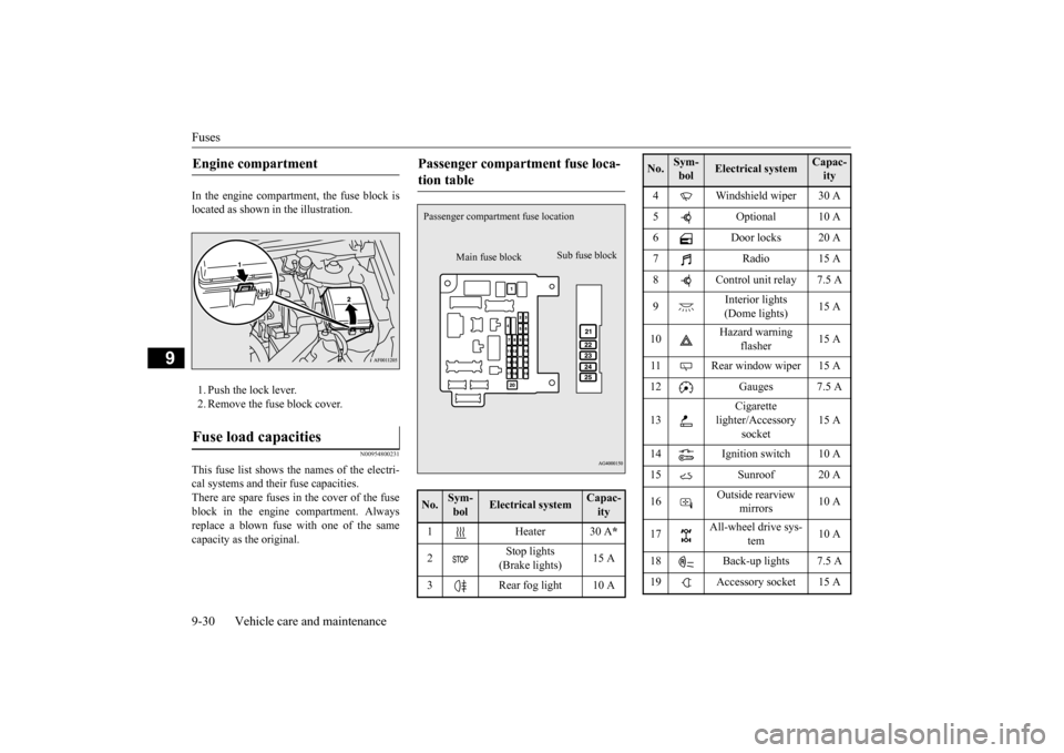
In the engine compartment, the fuse block is located as shown in the illustration. 1. Push the lock lever. 2. Remove the fuse block cover.
N00954800231
This fuse list shows the names of the electri- cal systems and their fuse capacities. There are spare fuses in the cover of the fuseblock in the engine compartment. Always replace a blown fuse with one of the same capacity as the original. Engine compartment Fuse load capacities
Passenger compartment fuse loca- tion table No.
Sym- bol
Electrical system
Capac-ity
1 Heater 30 A
*
2
Stop lights (Brake lights)
15 A
3 Rear fog light 10 A
Main fuse block
Sub fuse block
Passenger compartme
nt fuse location
4 Windshield wiper 30 A 5 Optional 10 A 6 Door locks 20 A 7Radio15 A8 Control unit relay 7.5 A 9
Interior lights (Dome lights)
15 A
10
Hazard warning
flasher
15 A
11 Rear window wiper 15 A 12 Gauges 7.5 A 13
Cigarette
lighter/Accessory
socket
15 A
14 Ignition switch 10 A 15 Sunroof 20 A 16
Outside rearview
mirrors
10 A
17
All-wheel drive sys-
tem
10 A
18 Back-up lights 7.5 A 19 Accessory socket 15 ANo.
Sym- bol
Electrical system
Capac-ity
BK0210300US.bo
ok 30 ページ 2014年4月8日 火曜日 午前10時46分
Page 389 of 434
Fuses 9-32 Vehicle care and maintenance
9
* - Fusible link Some fuses may not be installed on your vehicle, depending on the vehicle modelor specifications. The table above shows the main equip- ment corresponding to each fuse.
There are no 7.5 A, 25 A or 30 A spare fuses. If a fuse of one of these capacities blows,replace it temporarily by borrowing one of the fuses indicated below. 7.5 A: 10 A spare fuse25 A: 20 A spare fuse 30 A: 30 A audio amplifier fuse
16
Head- light (low/high beam) (left)
Dis- charge
20 A
17
Head- light (low/high beam) (right)
Dis- charge
20 A
18
Headlight (low beam) (left)
Halogen 10 A
19
Headlight (low beam) (right)
Halogen 10 A
20
ENG/ POWER
Except for vehi- cles with turbo- charger
10 A
I/C SPRAY
Vehicles with tur-bocharger
21 Ignition coil 10 ANo.
Sym- bol
Electrical system
Capac-ity
22
ENG/ POWER
Vehicles with tur-bocharger
20 A
ENG/ POWER
Except for vehi- cles with turbo- charger
20 A
Fuel line heater
25 A
23
Fuel pump
Except for vehi-cles with turbo- charger
15 A
Vehicles with tur- bocharger
20 A
24 Starter 30 A
*
25
Va l v e l i f t control
Except for vehi- cles with turbo- charger
40 A
*
——
Vehicles with tur-bocharger
—
26
Anti-lock braking
system
40 A
*
No.
Sym- bol
Electrical system
Capac-ity
27
Anti-lock braking
system
30 A
*
28
Air conditioning con- denser fan motor
30 A
*
29 Radiator fan motor 40 A
*
30 IOD IOD 30 A31 Audio amplifier 30 A 32 Diesel 30 A 33 — Spare fuse 10 A 34 — Spare fuse 15 A35 — Spare fuse 20 ANo.
Sym- bol
Electrical system
Capac-ity
BK0210300US.bo
ok 32 ページ 2014年4月8日 火曜日 午前10時46分
Page 390 of 434
Fuses
Vehicle care and maintenance 9-33
9
Replace the borrowed fuse with a fuse that has the correct capacity as soon as possible.
N00954900027
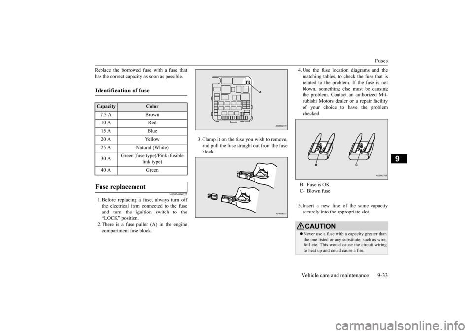
1. Before replacing a fuse, always turn offthe electrical item connected to the fuseand turn the ignition switch to the“LOCK” position. 2. There is a fuse puller (A) in the engine compartment fuse block.
3. Clamp it on the fuse you wish to remove, and pull the fuse straight out from the fuse block.
4. Use the fuse location diagrams and the matching tables, to check the fuse that is related to the problem. If the fuse is not blown, something else must be causingthe problem. Contact an authorized Mit- subishi Motors dealer or a repair facility of your choice to have the problemchecked. 5. Insert a new fuse of the same capacity securely into the appropriate slot.
Identification of fuse Capacity
Color
7.5 A Brown10 A Red15 A Blue20 A Yellow25 A Natural (White) 30 A
Green (fuse type)/Pink (fusible
link type)
40 A Green
Fuse replacement
B- Fuse is OK C- Blown fuseCAUTION Never use a fuse with a capacity greater than the one listed or any substitute, such as wire, foil etc. This would cause the circuit wiringto heat up and could cause a fire.
BK0210300US.bo
ok 33 ページ 2014年4月8日 火曜日 午前10時46分
Page 428 of 434
Alphabetical index
12-3
12
Front turn signal lights
Replacement
.................
.................
9-40
Front turn signal, parking and side-marker lightsBulb capacity
................
.................
9-34
Replacement
.........................
9-39
, 9-40
Fuel
Fuel economy
...................
................
6-2
Fuel hoses
.....................
.................
9-26
Modification/alterations to the electrical orfuel systems
...................
................
3-6
Tank capacity
..........................
3-4
, 11-6
Fuel Pump Shut-off System
.................
8-15
Fuel selection
....................
...................
3-2
Fuses
.........................
........................
9-29
Fusible links
..................
.....................
9-28
G
General maintenance
...........................
9-27
General vehicle data
............................
11-4
Genuine parts
....................
...................
3-6
Glove compartment
...........................
5-188
H
Hazard warning flasher switch
...........
5-153
Hazard warning lights
.......................
5-143
Head restraints
...................
...................
4-6
Headlight leveling switch
...................
5-152
Headlights
Bulb capacity
..................
...............
9-34
Dimmer
...................
.....................
5-150
Headlight flasher
...........................
5-150
Leveling switch
.............................
5-152
Replacement
...................
...............
9-36
Switch
.....................
.....................
5-147
Heater without air conditioning function
.7-4
High beam indicator
..........................
5-143
Hill start assist (vehicles with Twin Clutch SST)
.........................
......................
5-90
Hood lock release mechanism and safety catch
.........................
......................
9-28
Horn switch
.....................
.................
5-159
I
If the vehicle breaks down
.....................
8-2
Ignition switch
...........................
5-16
, 5-53
Important facts to know in case of an accident 10-4 Indicators
....................
.....................
5-143
Information screen display
.................
5-145
Inside day/night rearview mirror
..........
5-50
Inside emergency trunk lid release
.......
5-41
Interior lights
...................
.................
5-185
J
Jack
...........................
..........................
8-5
Storage
.........................
...................
8-5
Jump-starting the engine
........................
8-2
K
Key reminder buzzer
...........................
5-36
Keyless entry system
.............................
5-7
Keys
..........................
..........................
5-3
L
Labeling
........................
.....................
11-2
License plate light
Bulb capacity
................
.................
9-34
Replacement
..................
.................
9-45
Limited-slip differential
.......................
5-88
Link System
..................
...................
5-159
Loading information
..............................
6-6
Lubricants
.....................
.....................
11-6
Luggage floor boxes
..........................
5-190
M
Malfunction indicator
........................
5-144
Manual air conditioning
.......................
7-12
Manual transaxle
................
.................
5-59
Oil
.....................
...................
9-11
, 11-6
BK0210300US.bo
ok 3 ページ 2014年4月8日 火曜日 午前10時46分