door MITSUBISHI LANCER 2016 8.G Workshop Manual
[x] Cancel search | Manufacturer: MITSUBISHI, Model Year: 2016, Model line: LANCER, Model: MITSUBISHI LANCER 2016 8.GPages: 392, PDF Size: 13.12 MB
Page 232 of 392
Storage spaces 5-170 Features and controls
5
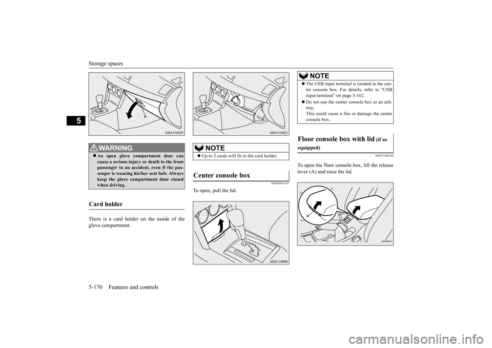
There is a card holder on the inside of the glove compartment.
N00546401101
To open, pull the lid.
N00551600188
To open the floor console box, lift the releaselever (A) and raise the lid.
WA R N I N G An open glove compartment door can cause a serious injury
or death to the front
passenger in an accident, even if the pas-senger is wearing his/her seat belt. Always keep the glove compartment door closed when driving.
Card holder
NOTE
Up to 2 cards will fit in the card holder.
Center console box
NOTE
The USB input terminal is located in the cen- ter console box. For details, refer to “USB input terminal” on page 5-162. Do not use the center console box as an ash- tray. This could cause a fire or damage the center console box.
Floor console box with lid
(if so
equipped)
BK0230300US.book
170 ページ 2015年7月30日 木曜日 午後8時38分
Page 239 of 392
Vehicle preparation before driving
Driving safety 6-3
6
N00629001741
For a safer and more enjoyable trip, always observe the following: Before starting the vehicle, make certain that you and all passengers are seated and wearing their seat belts properly (with children in the rear seat, in appropriaterestraints), and that all the doors are locked.
Move the driver’s seat as far backward as possible, while still keeping good visibil- ity, and good control of the steering wheel, brakes, accelerator, and controls.Check the instrument panel indicators and multi-information display for any possible problem. Move the front passenger seat as far back as possible. Make sure that infants and small children are properly restrained in accordance withall laws and regulations.
Check these by selecting the defroster mode, and set the blower switch on high. You should be able to feel the air blowing against the windshield. (Refer to “Defrosting or defogging the wind- shield and door windows” on page 7-7, 7-12, 7-17.) Check all the tires for heavy tread wear or uneven wear patterns. Look for stones, nails,glass, or other objects stuck in the tread. Look for any tread cuts or sidewall cracks. Check the wheel nuts for tightness, and the tires(including spare tire) for proper pressures.
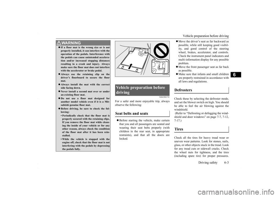
WA R N I N G If a floor mat is the wrong size or is not properly installed, it can interfere with the operation of the pedals. Interference with the pedals can cause unintended accelera- tion and/or increased stopping distancesresulting in a crash and injury. Always make sure the floor mat does not interfere with the accelerator or brake pedal. Always use the retaining clip on the driver’s floorboard to secure the floormat. Always install the mat with the correct side facing down. Never install a second mat over or under an existing floor mat. Do not use a floor mat designed for another model vehicle ev
en if it is a Mit-
subishi genuine floor mat. Before driving, be sure to check the fol- lowing:• Periodically check that the floor mat isproperly secured with the retaining clips. If you remove the floor mat while clean-ing the inside of your vehicle or for any other reason, always check the condition of the floor mat after it has been rein-stalled.• While the vehicle is stopped with the engine off, check that the floor mat is not interfering with the pedals by depressingthe pedals fully.
Vehicle preparation before driving Seat belts and seats
Defrosters Tires
BK0230300US.bo
ok 3 ページ 2015年7月30日 木曜日 午後8時38分
Page 242 of 392
Loading information 6-6 Driving safety
6
Your front bumper can be damaged if you scrape it over curbs or parking stop blocks.Be careful when traveling up or down steep slopes where your bumper can scrape the road. When leaving the vehicle unattended, always carry the key and lock all doors.Always try to park your vehicle in a well lit area.
N00629900349
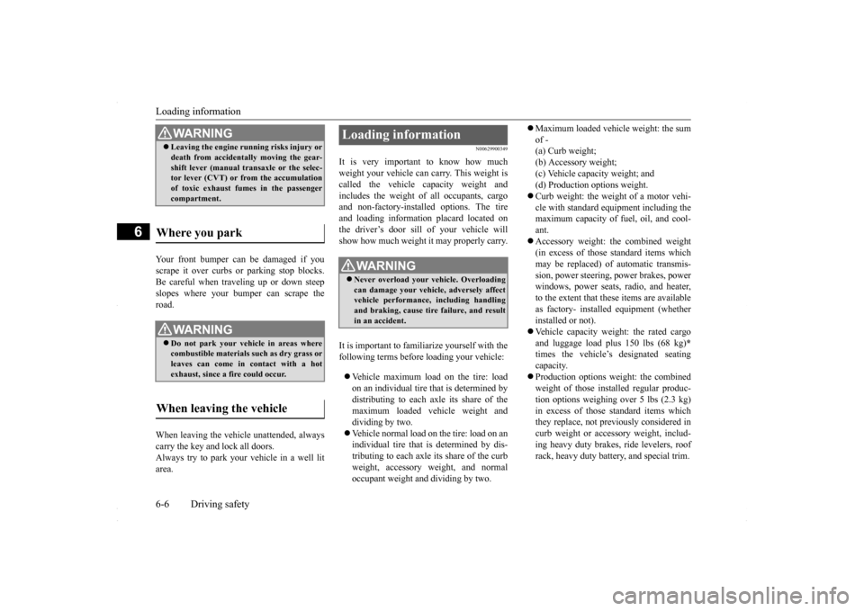
It is very important to know how much weight your vehicle can carry. This weight iscalled the vehicle capacity weight and includes the weight of all occupants, cargo and non-factory-installed options. The tireand loading information placard located on the driver’s door sill of your vehicle will show how much weight it may properly carry. It is important to familiarize yourself with the following terms before loading your vehicle: Vehicle maximum load on the tire: load on an individual tire that is determined by distributing to each axle its share of the maximum loaded vehicle weight anddividing by two. Vehicle normal load on the tire: load on an individual tire that is determined by dis-tributing to each axle its share of the curb weight, accessory weight, and normal occupant weight and dividing by two.
Maximum loaded vehicle weight: the sum of - (a) Curb weight; (b) Accessory weight;(c) Vehicle capacity weight; and (d) Production options weight. Curb weight: the weight of a motor vehi- cle with standard equipment including the maximum capacity of fuel, oil, and cool- ant. Accessory weight: the combined weight (in excess of those standard items which may be replaced) of automatic transmis- sion, power steering, power brakes, powerwindows, power seats, radio, and heater, to the extent that these items are available as factory- installed equipment (whetherinstalled or not). Vehicle capacity weight: the rated cargo and luggage load plus 150 lbs (68 kg)
*
times the vehicle’s designated seating capacity. Production options weight: the combined weight of those installed regular produc- tion options weighing over 5 lbs (2.3 kg) in excess of those standard items whichthey replace, not previously considered in curb weight or accessory weight, includ- ing heavy duty brakes, ride levelers, roofrack, heavy duty battery, and special trim.
WA R N I N G Leaving the engine running risks injury or death from accidentally moving the gear- shift lever (manual transaxle or the selec- tor lever (CVT) or from the accumulation of toxic exhaust fumes in the passengercompartment.
Where you park
WA R N I N G Do not park your vehicle in areas where combustible materials such as dry grass or leaves can come in contact with a hotexhaust, since a fire could occur.
When leaving the vehicle
Loading information
WA R N I N G Never overload your vehicle. Overloading can damage your vehicle, adversely affectvehicle performance, including handling and braking, cause tire failure, and result in an accident.
BK0230300US.bo
ok 6 ページ 2015年7月30日 木曜日 午後8時38分
Page 243 of 392
Loading information Driving safety 6-7
6
Normal occupant weight: 150 lbs (68 kg)
*
times the number of specified occupants. (In your vehicle the number is 3) Occupant distribution: distribution of occupants in a vehicle as specified. (In your vehicle the distribution is 2 in front, 1 in second row seat)
N00630100309
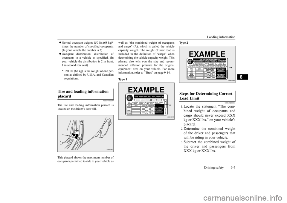
The tire and loading information placard islocated on the driver’s door sill. This placard shows the maximum number of occupants permitted to ride in your vehicle as
well as “the combined weight of occupants and cargo” (A), which is called the vehicle capacity weight. The weight of roof road is included in the definition of “cargo” whendetermining the vehicle capacity weight. This placard also tells you the size and recom- mended inflation pressure for the originalequipment tires on your vehicle. For more information, refer to “Tires” on page 9-14. Ty p e 1
Ty p e 2
N00630201235
1.Locate the statement “The com- bined weight of occupants and cargo should never exceed XXX kg or XXX lbs.” on your vehicle’splacard.2.Determine the combined weightof the driver and passengers thatwill be riding in your vehicle.3.Subtract the combined weight ofthe driver and passengers fromXXX kg or XXX lbs.
* :150 lbs (68 kg) is the weight of one per- son as defined by U.S.A. and Canadian regulations.
Tire and loading information placard
Steps for Determining Correct Load Limit
BK0230300US.bo
ok 7 ページ 2015年7月30日 木曜日 午後8時38分
Page 246 of 392
Cargo loads 6-10 Driving safety
6
N00629700464
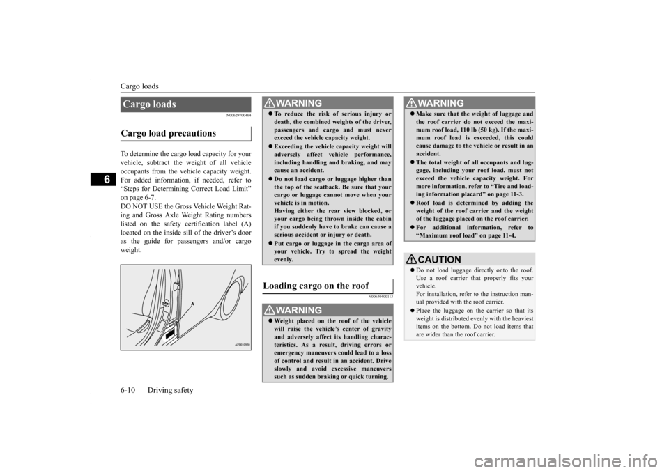
To determine the cargo load capacity for your vehicle, subtract the weight of all vehicleoccupants from the vehicle capacity weight. For added information, if needed, refer to “Steps for Determining Correct Load Limit”on page 6-7.DO NOT USE the Gross Vehicle Weight Rat- ing and Gross Axle Weight Rating numbers listed on the safety certification label (A)located on the inside sill of the driver’s door as the guide for passengers and/or cargo weight.
N00630400113
Cargo loads Cargo load precautions
WA R N I N G To reduce the risk of serious injury or death, the combined weights of the driver, passengers and cargo and must never exceed the vehicle capacity weight. Exceeding the vehicle capacity weight will adversely affect vehicle performance, including handling and braking, and maycause an accident. Do not load cargo or luggage higher than the top of the seatback. Be sure that your cargo or luggage cannot move when your vehicle is in motion.Having either the rear view blocked, or your cargo being thrown inside the cabin if you suddenly have to brake can cause aserious accident or injury or death. Put cargo or luggage in the cargo area of your vehicle. Try to spread the weight evenly.
Loading cargo on the roof
WA R N I N G Weight placed on the roof of the vehicle will raise the vehicle’s center of gravity and adversely affect its handling charac-teristics. As a result, driving errors or emergency maneuvers could lead to a loss of control and result in an accident. Driveslowly and avoid excessive maneuvers such as sudden braking or quick turning.
Make sure that the weight of luggage and the roof carrier do not exceed the maxi- mum roof load, 110 lb (50 kg). If the maxi- mum roof load is exceeded, this could cause damage to the ve
hicle or result in an
accident. The total weight of all occupants and lug- gage, including your roof load, must not exceed the vehicle capacity weight. For more information, refer to “Tire and load-ing information placard” on page 11-3. Roof load is determined by adding the weight of the roof carrier and the weight of the luggage placed on the roof carrier. For additional information, refer to “Maximum roof load” on page 11-4.CAUTION Do not load luggage directly onto the roof. Use a roof carrier th
at properly fits your
vehicle. For installation, refer to the instruction man- ual provided with the roof carrier. Place the luggage on the carrier so that its weight is distributed evenly with the heaviest items on the bottom. Do not load items that are wider than the roof carrier.WA R N I N G
BK0230300US.bo
ok 10 ページ 2015年7月30日 木曜日 午後8時38分
Page 253 of 392
Vents
Comfort controls 7-3
7
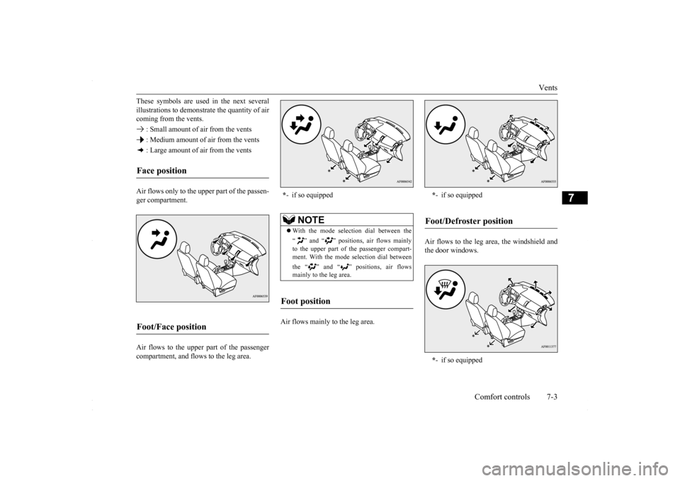
These symbols are used in the next several illustrations to demonstr
ate the quantity of air
coming from the vents. : Small amount of air from the vents : Medium amount of air from the vents : Large amount of air from the vents Air flows only to the upper part of the passen- ger compartment. Air flows to the upper part of the passenger compartment, and flows to the leg area.
Air flows mainly to the leg area.
Air flows to the leg area, the windshield and the door windows.
Face position Foot/Face position
* - if so equipped
NOTE
With the mode selection dial between the “ ” and “ ” positions, air flows mainly to the upper part of the passenger compart- ment. With the mode selection dial between the “ ” and “ ” positions, air flows mainly to the leg area.
Foot position
* - if so equipped
Foot/Defroster position *- if so equipped
BK0230300US.bo
ok 3 ページ 2015年7月30日 木曜日 午後8時38分
Page 254 of 392
Heater without air conditioni
ng function (if so equipped)
7-4 Comfort controls
7
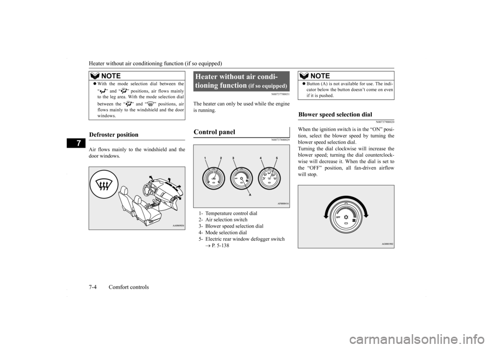
Air flows mainly to the windshield and the door windows.
N00737700031
The heater can only be used while the engineis running.
N00737800029
N00737900020
When the ignition switch is in the “ON” posi- tion, select the blower speed by turning theblower speed selection dial. Turning the dial clockwise will increase the blower speed; turning the dial counterclock-wise will decrease it. When the dial is set to the “OFF” position, all fan-driven airflow will stop.
NOTE
With the mode selection dial between the “ ” and “ ” positions, air flows mainly to the leg area. With the mode selection dial between the “ ” and “ ” positions, air flows mainly to the windshield and the door windows.
Defroster position
Heater without air condi- tioning function
(if so equipped)
Control panel
1- Temperature control dial 2- Air selection switch 3- Blower speed selection dial 4- Mode selection dial5- Electric rear window defogger switch
P. 5-138
NOTE
Button (A) is not available for use. The indi- cator below the button doesn’t come on even if it is pushed.
Blower speed selection dial
BK0230300US.bo
ok 4 ページ 2015年7月30日 木曜日 午後8時38分
Page 257 of 392
Automatic air conditioning with
Fahrenheit scale (if so equipped)
Comfort controls 7-7
7
N00738500065
Set the mode selection dial (between “ ” or “ ”) to remove frost or mist from the wind- shield and door window. Use this setting to keep the windshield and door windows clear of mist, and to keep the leg area heated (when driving in rain orsnow). 1. Set the mode selection dial to the “ ”
2. Select your desired blower speed by turn- ing the blower speed selection dial. 3. Select your desired temperature by turn- ing the temperature control dial.
For quick defrosting 1. Set the mode selection dial to the “ ” 2. Set your blower to the maximum speed. 3. Set the temperature to the highest posi-tion.
N00731500226
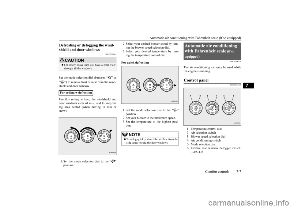
The air conditioning can only be used whilethe engine is running.
N00711801565
Defrosting or defogging the wind- shield and door windows
CAUTION For safety, make sure you have a clear view through all the windows.
For ordinary defrosting
NOTE
To defog quickly, direct
the air flow from the
side vents toward the door windows.
Automatic air conditioning with Fahrenheit scale
(if so
equipped)Control panel
1- Temperature control dial 2- Air selection switch 3- Blower speed selection dial4- Air conditioning switch 5- Mode selection dial 6- Electric rear window defogger switch
P.5-138
BK0230300US.bo
ok 7 ページ 2015年7月30日 木曜日 午後8時38分
Page 262 of 392
Automatic air conditioning with
Celsius scale (if so equipped)
7-12 Comfort controls
7
operation, set the dials to the “AUTO” posi- tion.
N00732400280
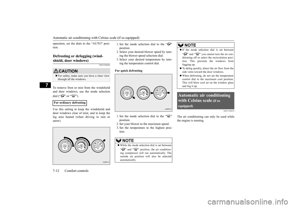
To remove frost or mist from the windshield and door windows, use
the mode selection
dial (“ ” or “ ”). Use this setting to keep the windshield and door windows clear of mist, and to keep the leg area heated (when driving in rain or snow).
1. Set the mode selection dial to the “ ”2. Select your desired
blower speed by turn-
ing the blower speed selection dial. 3. Select your desired temperature by turn-ing the temperature control dial.
For quick defrosting 1. Set the mode selection dial to the “ ” 2. Set your blower to the maximum speed. 3. Set the temperature to the highest posi-tion.
N00731500239
The air conditioning can only be used whilethe engine is running.
Defrosting or defogging (wind- shield, door windows)
CAUTION For safety, make sure you have a clear view through all the windows.
For ordinary defrosting
NOTE
While the mode selection dial is set between “ ” and “ ” position, the air condition- ing compressor will run automatically. The outside air position will also be selected automatically.
If the mode selection dial is set between “ ” and “ ” you cannot turn the air con- ditioning off or select the recirculation posi- tion. This prevents the windows fromfogging up. To defog quickly, direct
the air flow from the
side vents toward the door windows. When defrosting, do not set the temperature control dial to the maximum cool position. This will blow cool air on the window glass and fog it up.
Automatic air conditioning with Celsius scale
(if so
equipped)
NOTE
BK0230300US.bo
ok 12 ページ 2015年7月30日 木曜日 午後8時38分
Page 267 of 392
Automatic air conditioning with
Celsius scale (if so equipped)
Comfort controls 7-17
7
selection dial and the mode selection dial to the desired positions. To return to automatic operation, set the dials to the “AUTO” posi- tion.
N00732400440
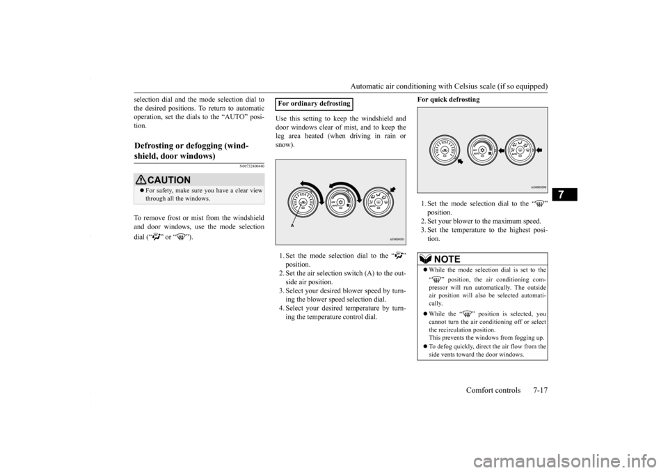
To remove frost or mist from the windshieldand door windows, use
the mode selection
dial (“ ” or “ ”).
Use this setting to keep the windshield and door windows clear of mist, and to keep the leg area heated (when driving in rain or snow). 1. Set the mode selection dial to the “ ”2. Set the air selection switch (A) to the out- side air position. 3. Select your desired blower speed by turn-ing the blower speed selection dial. 4. Select your desired temperature by turn- ing the temperature control dial.
For quick defrosting 1. Set the mode selection dial to the “ ” 2. Set your blower to the maximum speed. 3. Set the temperature to the highest posi-tion.
Defrosting or defogging (wind- shield, door windows)
CAUTION For safety, make sure you have a clear view through all the windows.
For ordinary defrosting
NOTE
While the mode selection dial is set to the “ ” position, the air conditioning com- pressor will run automatically. The outside air position will also be selected automati-cally. While the “ ” position is selected, you cannot turn the air conditioning off or select the recirculation position.This prevents the windows from fogging up. To defog quickly, direct
the air flow from the
side vents toward the door windows.
BK0230300US.bo
ok 17 ページ 2015年7月30日 木曜日 午後8時38分