wheel nut MITSUBISHI LANCER 2016 8.G Owners Manual
[x] Cancel search | Manufacturer: MITSUBISHI, Model Year: 2016, Model line: LANCER, Model: MITSUBISHI LANCER 2016 8.GPages: 392, PDF Size: 13.12 MB
Page 115 of 392
Ignition switch
Features and controls 5-53
5
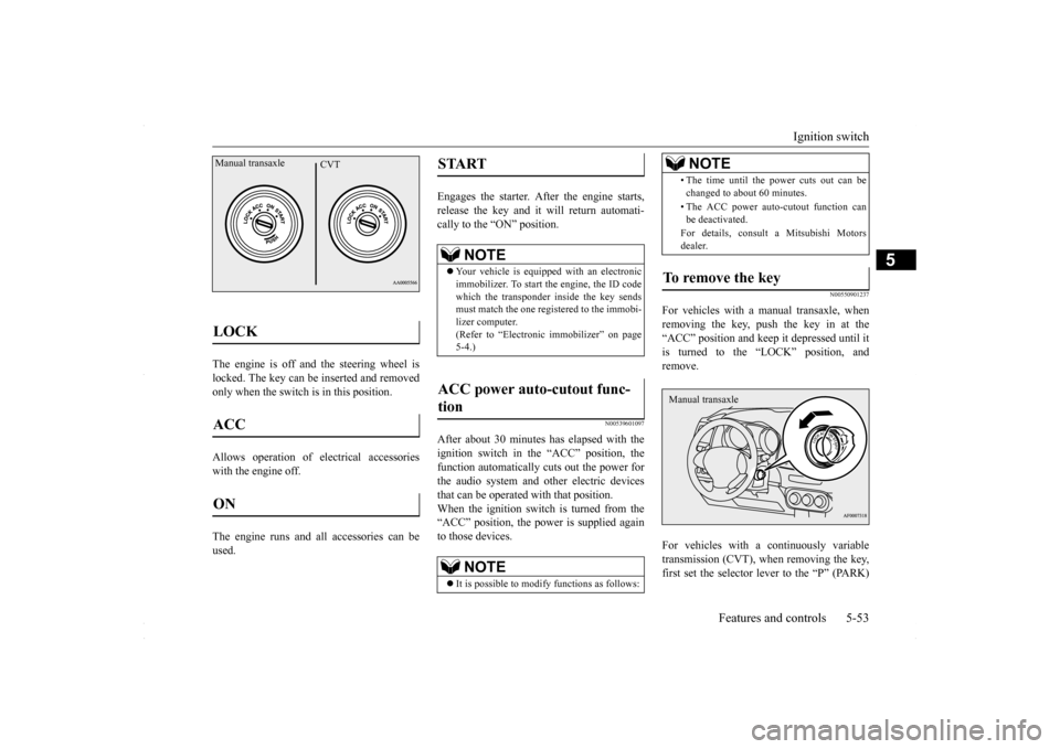
The engine is off and the steering wheel is locked. The key can be inserted and removedonly when the switch is in this position. Allows operation of electrical accessories with the engine off. The engine runs and all accessories can be used.
Engages the starter. After the engine starts, release the key and it will return automati-cally to the “ON” position.
N00539601097
After about 30 minutes has elapsed with theignition switch in the “ACC” position, the function automatically cuts out the power for the audio system and other electric devicesthat can be operated with that position. When the ignition switch is turned from the “ACC” position, the power is supplied againto those devices.
N00550901237
For vehicles with a manual transaxle, whenremoving the key, push the key in at the“ACC” position and keep it depressed until it is turned to the “LOCK” position, and remove. For vehicles with a continuously variable transmission (CVT), when removing the key,first set the selector lever to the “P” (PARK)
LOCK ACC ON Manual transaxle
CVT
START
NOTE
Your vehicle is equipped with an electronic immobilizer. To start the engine, the ID code which the transponder inside the key sendsmust match the one registered to the immobi- lizer computer. (Refer to “Electronic immobilizer” on page5-4.)
ACC power auto-cutout func- tion
NOTE
It is possible to modify functions as follows:
• The time until the power cuts out can be changed to about 60 minutes. • The ACC power auto-cutout function can be deactivated. For details, consult a Mitsubishi Motors dealer.
To remove the key
NOTE
Manual transaxle
BK0230300US.bo
ok 53 ページ 2015年7月30日 木曜日 午後8時38分
Page 118 of 392
Starting and stopping the engine 5-56 Features and controls
5
7. Turn the ignition switch to the “ON” posi- tion and make certain that all warning lights are functioning properly beforestarting the engine.8. Turn the ignition switch to the “START” pedal. Release the key when the enginestarts.
After several attempts, you may experience that the engine still does not start. 1. Make sure that all electric devices, such as lights, air conditioning blower and rearwindow defogger, are turned off.
2. While depressing the brake pedal on vehi- cles equipped with continuously variable transmission (CVT) or the clutch pedal on the vehicles equipped with manual trans-axle, press the accelerator pedal halfway and hold it there, then crank the engine. Release the accelerator pedal, immedi-ately after the engine starts. 3. If the engine still will not start, the engine could be flooded with too much gasoline.While depressing the brake pedal on vehi-cles equipped with CVT or the clutch pedal on the vehicles
equipped with man-
ual transaxle, push the accelerator pedalall the way down and hold it there, then crank the engine for 5 to 6 seconds. Return the ignition switch to the “LOCK”position and release the accelerator pedal. Wait a few seconds, and then crank the engine again for 5 to 6 seconds whiledepressing the brake pedal or the clutch pedal, but do not push the accelerator pedal. Release the ignition key if theengine starts. If the engine fails to start, repeat these procedures. If the engine still will not start, contact your local Mitsubi-shi Motors dealer or a repair facility of your choice for assistance.
When the ambient temperature is -4 °F (-20 °C) or lower on vehicles with CVT, itmay not be possible to start from a standstill even with the selector lever in the “D” (DRIVE) or “R” (REVERSE) position.This phenomenon occurs because the trans-axle has not warmed up sufficiently; it does not indicate a problem. If it occurs, place the selector lever in the “P” (PARK) position andlet the engine idle for at least 10 minutes. The transaxle will warm up, and you will be able to start normally.Do not leave the vehicle during warm-up operation.
N00542301102
1. Bring the vehicle to a complete stop. 2. Fully engage the parking brake while depressing the brake pedal. 3. For vehicles with a manual transaxle, turn the ignition switch to the “LOCK” posi- tion to stop the engine, and then move thegearshift lever to the 1st (on a uphill) or “R” (Reverse) (on a downhill) position.
NOTE
On vehicles with CVT, the starter will not operate unless the selector lever is in the “P” (PARK) or “N” (NEUTRAL) position. For safety reasons, start the engine in the “P” (PARK) position so that the wheels arelocked.NOTE
Minor noises may be heard on engine start- up. These will disappear as the engine warms up.
When the engine is hard to start
Startability of continuously vari- able transmission (CVT) vehicles at extremely cold ambient temper- ature Stopping the engine
BK0230300US.bo
ok 56 ページ 2015年7月30日 木曜日 午後8時38分
Page 131 of 392
Electronically controlled 4WD system (if so equipped)
Features and controls 5-69
5
N00549400017
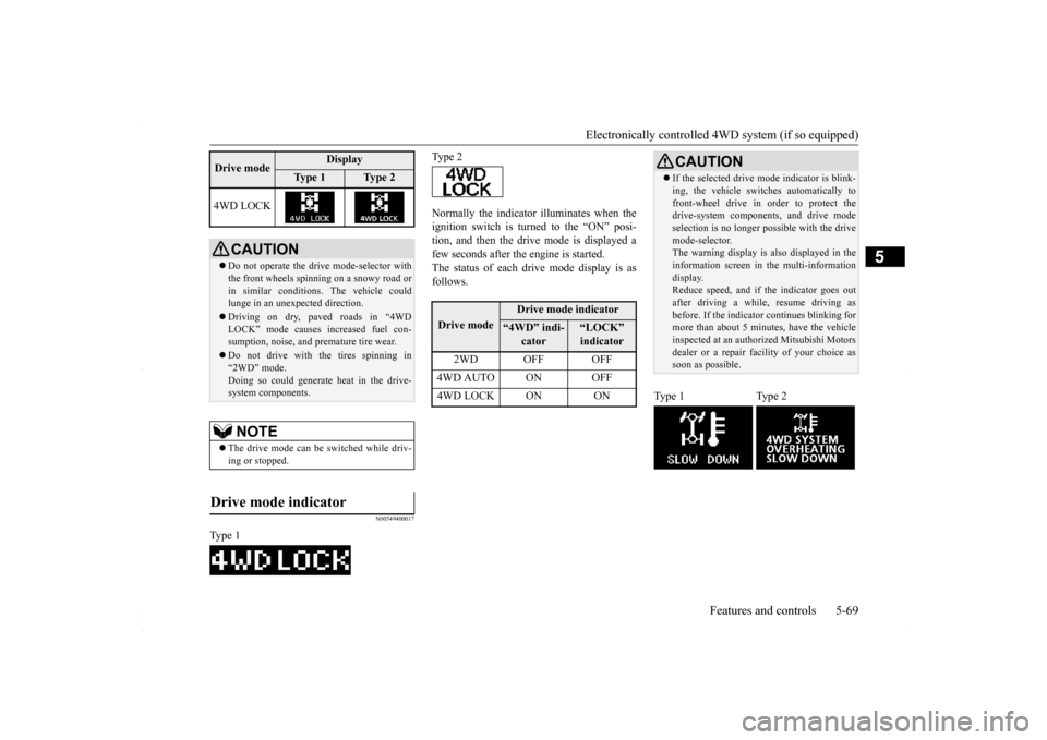
Normally the indicator illuminates when the ignition switch is turned to the “ON” posi- tion, and then the drive mode is displayed afew seconds after the engine is started. The status of each drive mode display is as follows.
4WD LOCK
CAUTION Do not operate the drive mode-selector with the front wheels spinning on a snowy road or in similar conditions. The vehicle couldlunge in an unexpected direction. Driving on dry, paved roads in “4WD LOCK” mode causes increased fuel con- sumption, noise, and premature tire wear. Do not drive with the tires spinning in “2WD” mode. Doing so could generate heat in the drive-system components.NOTE
The drive mode can be switched while driv- ing or stopped.
Drive mode indicator
Type 1Drive mode
Display
Ty p e 1
Ty p e 2
Type 2Drive mode
Drive mode indicator
“4WD” indi-
cator
“LOCK” indicator
2WD OFF OFF
4WD AUTO ON OFF4WD LOCK ON ON
CAUTION If the selected drive m
ode indicator is blink-
ing, the vehicle switches automatically to front-wheel drive in order to protect the drive-system components, and drive mode selection is no longer pos
sible with the drive
mode-selector. The warning display is also displayed in the information screen in the multi-informationdisplay. Reduce speed, and if the indicator goes out after driving a while, resume driving asbefore. If the indicator continues blinking for more than about 5 minutes, have the vehicle inspected at an authorized Mitsubishi Motorsdealer or a repair facility of your choice as soon as possible.
Type 1 Type 2
BK0230300US.bo
ok 69 ページ 2015年7月30日 木曜日 午後8時38分
Page 148 of 392
Tire pressure monitoring system 5-86 Features and controls
5
Accordingly, when the low tire pressure tell- tale illuminates, you should stop and check your tires as soon as possible, and inflate them to the proper pressure. Driving on a sig-nificantly under-inflated tire causes the tire to overheat and can lead to tire failure. Under-inflation also reduces fuel efficiencyand tire tread life, and may affect the vehi- cle’s handling and stopping ability. Please note that the TPMS is not a substitute forproper tire maintenance, and it is the driver’sresponsibility to maintain correct tire pres- sure, even if under-inflation has not reached the level to trigger illumination of the TPMSlow tire pressure telltale. Your vehicle has also been equipped with a TPMS malfunction indicator to indicate whenthe system is not operating properly. The TPMS malfunction indicator is combined with the low tire pressure telltale.When the system detects a malfunction, the telltale will flash for approximately one min- ute and then remain continuously illuminated.This sequence will continue upon subsequent vehicle start-ups as long as the malfunction exists.When the malfunction indicator is illumi- nated, the system may not be able to detect or signal low tire pressure as intended.TPMS malfunctions may occur for a variety of reasons, including the installation of replacement or alternate tires or wheels on the
vehicle that prevent the TPMS from function- ing properly. Always check the TPMS mal- function telltale after replacing one or more tires or wheels on your vehicle to ensure thatthe replacement or alternate tires and wheels allow the TPMS to continue to function prop- erly.
N00532800439
1. If the tire pressure monitoring systemwarning light illuminates, avoid hardbraking, sharp steering maneuvers and high speeds. You should stop and adjust the tires to the proper inflation pressure assoon as possible. Adjust the spare tire at the same time. Refer to “Tires” on page 9-14.
2. If the tire pressure monitoring system warning light remains illuminated afteryou have been driving for about 20 min- utes after you adjust the tire inflation pres- sure, one or more of the tires may have apuncture. Inspect the tire and if it has a puncture, have it repaired by an autho- rized Mitsubishi Motors dealer as soon aspossible.
If the warning light/display illu- minates while driving
NOTE
In addition, the warning display is displayed on the information screen in the multi-infor-mation display. When inspecting or adjusting the tire pres- sure, do not apply excessive force to the valve stem to avoid breakage.
After inspecting or adjusting the tire pres- sure, always reinstall the valve cap on the valve stem. Without the valve cap, dirt or moisture could get into the valve, resulting in damage to thetire inflation pressure sensor. Do not use metal valve caps, which may cause a metal reaction, resulting in corrosion and damage of the tire inflation pressure sen- sors. Once adjustments have been made, the warn- ing light will go off after a few minutes ofdriving.WA R N I N G If the warning light/display illuminates while you are driving, avoid hard braking, sharp steering maneuvers and highspeeds. Driving with an under-inflated tire adversely affects vehicle performance and can result in an accident.NOTE
BK0230300US.bo
ok 86 ページ 2015年8月4日 火曜日 午後3時5分
Page 239 of 392
Vehicle preparation before driving
Driving safety 6-3
6
N00629001741
For a safer and more enjoyable trip, always observe the following: Before starting the vehicle, make certain that you and all passengers are seated and wearing their seat belts properly (with children in the rear seat, in appropriaterestraints), and that all the doors are locked.
Move the driver’s seat as far backward as possible, while still keeping good visibil- ity, and good control of the steering wheel, brakes, accelerator, and controls.Check the instrument panel indicators and multi-information display for any possible problem. Move the front passenger seat as far back as possible. Make sure that infants and small children are properly restrained in accordance withall laws and regulations.
Check these by selecting the defroster mode, and set the blower switch on high. You should be able to feel the air blowing against the windshield. (Refer to “Defrosting or defogging the wind- shield and door windows” on page 7-7, 7-12, 7-17.) Check all the tires for heavy tread wear or uneven wear patterns. Look for stones, nails,glass, or other objects stuck in the tread. Look for any tread cuts or sidewall cracks. Check the wheel nuts for tightness, and the tires(including spare tire) for proper pressures.
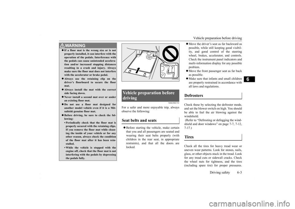
WA R N I N G If a floor mat is the wrong size or is not properly installed, it can interfere with the operation of the pedals. Interference with the pedals can cause unintended accelera- tion and/or increased stopping distancesresulting in a crash and injury. Always make sure the floor mat does not interfere with the accelerator or brake pedal. Always use the retaining clip on the driver’s floorboard to secure the floormat. Always install the mat with the correct side facing down. Never install a second mat over or under an existing floor mat. Do not use a floor mat designed for another model vehicle ev
en if it is a Mit-
subishi genuine floor mat. Before driving, be sure to check the fol- lowing:• Periodically check that the floor mat isproperly secured with the retaining clips. If you remove the floor mat while clean-ing the inside of your vehicle or for any other reason, always check the condition of the floor mat after it has been rein-stalled.• While the vehicle is stopped with the engine off, check that the floor mat is not interfering with the pedals by depressingthe pedals fully.
Vehicle preparation before driving Seat belts and seats
Defrosters Tires
BK0230300US.bo
ok 3 ページ 2015年7月30日 木曜日 午後8時38分
Page 315 of 392
Tools and jack
For emergencies 8-5
8
9. Start the engine, and slowly add coolant, up to the bottom of the filler neck. Useplain water if you have to (and replace it with the right coolant as soon as possible).
10. Replace the radiator cap and tighten it
fully. Check the engine coolant tempera- ture display on the multi-information dis- play. You can start driving again when thebar graph for the engine coolant tempera- ture display returns to the normal zone.
11. Have your vehicle checked by your autho-
rized Mitsubishi Motors dealer or a repair facility of your choice.
N00836600265
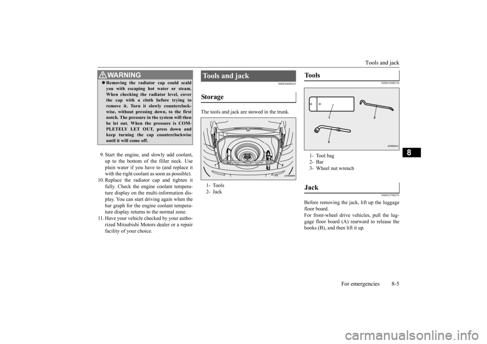
The tools and jack are stowed in the trunk.
N00832600124 N00832700255
Before removing the jack, lift up the luggage floor board. For front-wheel drive vehicles, pull the lug-gage floor board (A) rearward to release the hooks (B), and then lift it up.
WA R N I N G Removing the radiator cap could scald you with escaping hot water or steam. When checking the radiator level, cover the cap with a cloth before trying to remove it. Turn it slowly counterclock-wise, without pressing down, to the first notch. The pressure in the system will then be let out. When the pressure is COM-PLETELY LET OUT, press down and keep turning the cap counterclockwise until it will come off.
Tools and jack Storage 1- Tools 2- Jack
Tools 1- Tool bag2- Bar3- Wheel nut wrenchJack
BK0230300US.bo
ok 5 ページ 2015年7月30日 木曜日 午後8時38分
Page 317 of 392
How to change a tire
For emergencies 8-7
8
6. Get the jack, bar and wheel nut wrench ready.Refer to “Tools and jack” on page 8-5.
N00849600298
The compact spare tire is designed to savespace in the trunk. Its lighter weight makes iteasier to use if a flat tire occurs.
N00849701339
1. Lift up the luggage floor board.For front-wheel drive vehicles, pull theluggage floor board (A) rearward to release the hooks (B), and then lift it up.
NOTE
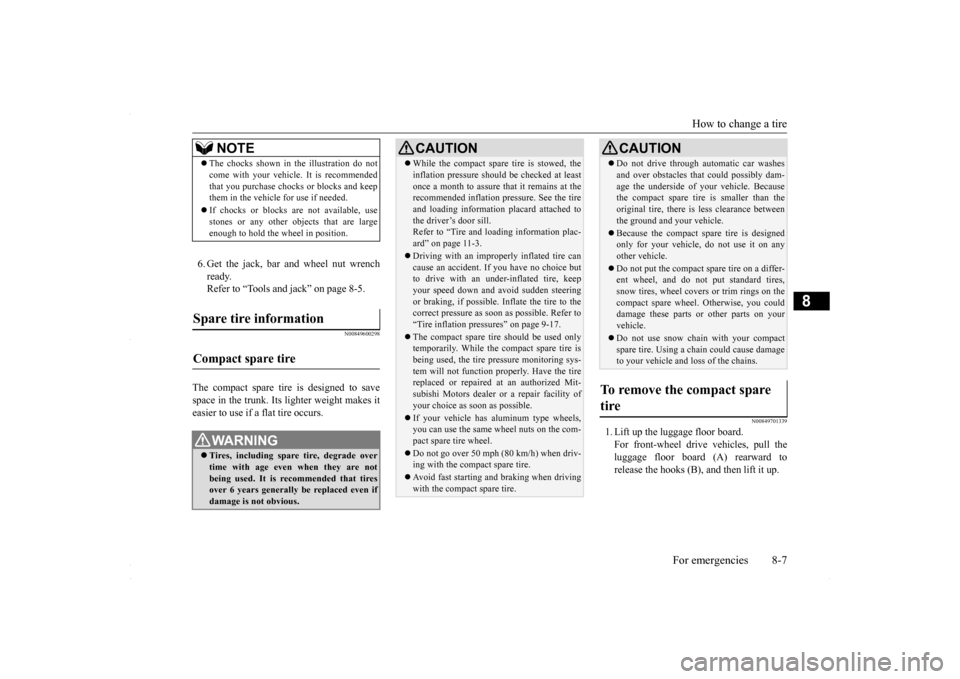
The chocks shown in the illustration do not come with your vehicle. It is recommended that you purchase chocks or blocks and keep them in the vehicle for use if needed. If chocks or blocks are not available, use stones or any other objects that are large enough to hold the wheel in position.
Spare tire information Compact spare tire
WA R N I N G Tires, including spare tire, degrade over time with age even when they are not being used. It is recommended that tiresover 6 years generally be replaced even if damage is not obvious.
CAUTION While the compact spare tire is stowed, the inflation pressure should be checked at least once a month to assure that it remains at the recommended inflation pressure. See the tire and loading information placard attached tothe driver’s door sill. Refer to “Tire and loading information plac- ard” on page 11-3. Driving with an improperly inflated tire can cause an accident. If you have no choice butto drive with an under-inflated tire, keep your speed down and avoid sudden steering or braking, if possible
. Inflate the tire to the
correct pressure as soon as possible. Refer to “Tire inflation pressures” on page 9-17. The compact spare tire should be used only temporarily. While the compact spare tire is being used, the tire pressure monitoring sys-tem will not function properly. Have the tire replaced or repaired at an authorized Mit- subishi Motors dealer or a repair facility ofyour choice as soon as possible. If your vehicle has aluminum type wheels, you can use the same wheel nuts on the com- pact spare tire wheel. Do not go over 50 mph (80 km/h) when driv- ing with the compact spare tire. Avoid fast starting and braking when driving with the compact spare tire.
Do not drive through automatic car washes and over obstacles that could possibly dam- age the underside of your vehicle. Because the compact spare tire is smaller than the original tire, there is less clearance betweenthe ground and your vehicle. Because the compact spare tire is designed only for your vehicle, do not use it on any other vehicle. Do not put the compact spare tire on a differ- ent wheel, and do not put standard tires, snow tires, wheel covers or trim rings on thecompact spare wheel. Otherwise, you could damage these parts or other parts on your vehicle. Do not use snow chain with your compact spare tire. Using a chain could cause damageto your vehicle and loss of the chains.
To remove the compact spare tire
CAUTION
BK0230300US.bo
ok 7 ページ 2015年7月30日 木曜日 午後8時38分
Page 318 of 392
How to change a tire 8-8 For emergencies
8
2. To remove the spare tire, remove the installation clamp (C) by turning it coun-terclockwise.
N00849801486
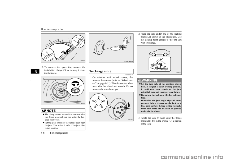
1. On vehicles with wheel covers, firstremove the covers (refer to “Wheel cov-ers” on page 8-11). Then loosen the wheel nuts with the wheel nut wrench. Do not remove the wheel nuts yet.
2. Place the jack under
one of the jacking
points (A) shown in the illustration. Use the jacking point closest to the tire you wish to change. 3. Rotate the jack by hand until the flange portion (B) fits in the groove (C) at the top of the jack.
NOTE
The clamp cannot be used for a normal size tire. Store a normal size tire under the lug-gage floor board. Put the spare tire under the vehicle body near the jack. This makes it safer if the jack slips out of position.
To change a tire
WA R N I N G Set the jack only at the positions shown here. If the jack is set at a wrong position,it could dent your vehicle or the jack might fall over and cause personal injury. Do not use the jack on a tilted or soft sur- face. Otherwise, the jack might slip and causepersonal injury. Always use the jack on a flat, hard surface. Before setting the jack, make sure there are no sand or pebblesunder the jack base.
BK0230300US.bo
ok 8 ページ 2015年7月30日 木曜日 午後8時38分
Page 319 of 392

How to change a tire
For emergencies 8-9
8
4. Make sure that the flange portion at the jacking point fits in the groove at the topof the jack. Insert the bar (D) into the wheel nut wrench (E). Then put the end of the bar into the shaft’s jack end, as shownin the illustration. Slowly rotate the wheel nut wrench until the tire is raised slightly off the groundsurface.
5. Remove the wheel nuts with the wheel nut wrench, then take the wheel off.
6. Clean out any mud, etc. on the hub sur- face (F), hub bolts (G) or in the installa- tion holes (H) in the wheel, and then mount the spare tire.
WA R N I N G Stop jacking up the vehicle as soon as the tire is raised off the ground. It is danger- ous to raise the vehicle any higher. Never get under the vehicle or put any portion of your body under the vehicle while it is support
ed by the jack.
Do not bump the raised vehicle or leave it sitting on the jack for a long time. Both are very dangerous. Do not use a jack except the one that came with your vehicle. The jack should not be used for any pur- pose other than to change a tire. No one should be in your vehicle when using the jack. Do not start or run the engine while your vehicle is on the jack. Do not turn the raised wheel. The tires that are still on the ground could turn andmake your vehicle fall off the jack. CAUTION Handle the wheel carefully when changing the tire, to avoid scratching the wheel sur- face.
WA R N I N G Mount the spare wheel with the valve stem (I) facing outboard. If you cannot see the valve stem (I), you have installed the wheel backwards.Operating the vehicle with the spare wheel installed backwards can cause vehicle damage and result in an accident.
BK0230300US.bo
ok 9 ページ 2015年7月30日 木曜日 午後8時38分
Page 320 of 392

How to change a tire 8-10 For emergencies
8
7. [Vehicle with steel wheels] • Normal wheels and compact spare wheel Install the wheel nuts (tapered nuts) withtheir tapered ends facing inward, then tighten by hand until the wheel is no lon- ger loose. [Vehicle with aluminum wheels] • Normal wheels
Temporarily tighten the wheel nuts (flange nuts) until their flange section comes in contact with the wheel and it is no longer loose. • Compact spare wheel Install the wheel nuts with their tapered ends facing inward, then tighten by hand until the wheel is no longer loose.
8. Lower the vehicle slowly by rotating the wheel nut wrench counterclockwise until the tire touches the ground. 9. Tighten the nuts in the order shown in the illustration until each nut has been tight-ened to the torque listed here. 65 to 80 ft-lb (88 to 108 N•m)CAUTION Never apply oil to either the wheel bolts or the nuts or they will tighten too much.NOTE
Flange nuts can be temporarily used on the compact spare or steel wheel, but return them to the original wheel and tire as soon aspossible. If all four wheels are changed to steel wheels, use tapered nuts.
BK0230300US.bo
ok 10 ページ 2015年7月30日 木曜日 午後8時38分