change wheel MITSUBISHI LANCER 2017 8.G Owners Manual
[x] Cancel search | Manufacturer: MITSUBISHI, Model Year: 2017, Model line: LANCER, Model: MITSUBISHI LANCER 2017 8.GPages: 385, PDF Size: 14.34 MB
Page 36 of 385
Seat belts
Seat and restraint systems 4-9
4
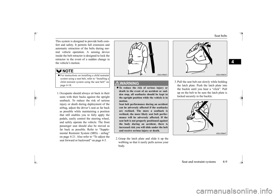
This system is designed to provide both com- fort and safety. It permits full extension and automatic retraction of the belts during nor- mal vehicle operation. A sensing deviceinside the belt retractor is designed to lock the retractor in the event of a sudden change in the vehicle’s motion. 1. Occupants should always sit back in their seats with their backs against the upright seatback. To reduce the risk of serious injury or death during deployment of theairbag, adjust the driver’s seat as far back as possible while maintaining a position that still enables you to fully apply thepedals, easily control the steering wheel, and safely operate the vehicle. The front passenger seat should also be moved asfar back as possible. Refer to “Supple- mental Restraint System (SRS) - airbag” on page 4-21. Also refer to “To adjust theseat forward or backward” on page 4-3.
2. Grasp the latch plate and slide it up the webbing so that it easily pulls across your body.
3. Pull the seat belt out slowly while holding the latch plate. Push the latch plate into the buckle until you hear a “click”. Pullup on the belt to be sure the latch plate is locked securely in the buckle.
NOTE
For instructions on installing a child restraint system using a seat belt, refer to “Installing achild restraint system using the seat belt” on page 4-18.
WA R N I N G To reduce the risk of serious injury or death in the event of an accident or sud- den stop, all seatbacks should be kept inthe upright position while the vehicle is in motion. Seat belt performance during an accidentcan be adversely affected if the seatbacks are reclined. The more a seatback is reclined, the more likely seat belt perfor-mance will be adversely affected. If the seat belt is not properly positioned against the body during an accident, there isincreased risk you will slide under the belt and receive serious injury or death.
BK0237700US.bo
ok 9 ページ 2016年4月15日 金曜日 午前11時28分
Page 118 of 385
Ignition switch
Features and controls 5-53
5
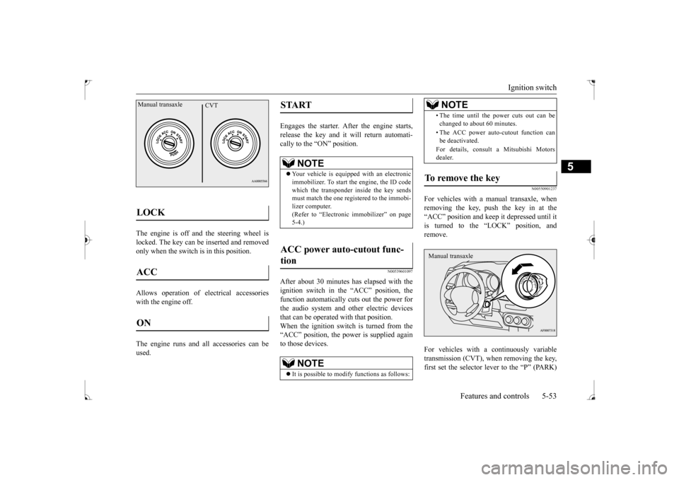
The engine is off and the steering wheel is locked. The key can be inserted and removedonly when the switch is in this position. Allows operation of electrical accessories with the engine off. The engine runs and all accessories can be used.
Engages the starter. After the engine starts, release the key and it will return automati-cally to the “ON” position.
N00539601097
After about 30 minutes has elapsed with theignition switch in the “ACC” position, the function automatically cuts out the power for the audio system and other electric devicesthat can be operated with that position. When the ignition switch is turned from the “ACC” position, the power is supplied againto those devices.
N00550901237
For vehicles with a manual transaxle, whenremoving the key, push the key in at the“ACC” position and keep it depressed until it is turned to the “LOCK” position, and remove. For vehicles with a continuously variable transmission (CVT), when removing the key,first set the selector lever to the “P” (PARK)
LOCK ACC ON Manual transaxle
CVT
START
NOTE
Your vehicle is equipped with an electronic immobilizer. To start the engine, the ID code which the transponder inside the key sendsmust match the one registered to the immobi- lizer computer. (Refer to “Electronic immobilizer” on page5-4.)
ACC power auto-cutout func- tion
NOTE
It is possible to modify functions as follows:
• The time until the power cuts out can be changed to about 60 minutes. • The ACC power auto-cutout function can be deactivated. For details, consult a Mitsubishi Motors dealer.
To remove the key
NOTE
Manual transaxle
BK0237700US.bo
ok 53 ページ 2016年4月15日 金曜日 午前11時28分
Page 129 of 385
Continuously variable transm
ission (CVT) (if so equipped)
5-64 Features and controls
5
This position is for driving up very steep hills and for engine braki
ng at low speeds when
driving down steep hills.
N00514401469
Whether the vehicle is stationary or in motion, sports mode is selected by pushing
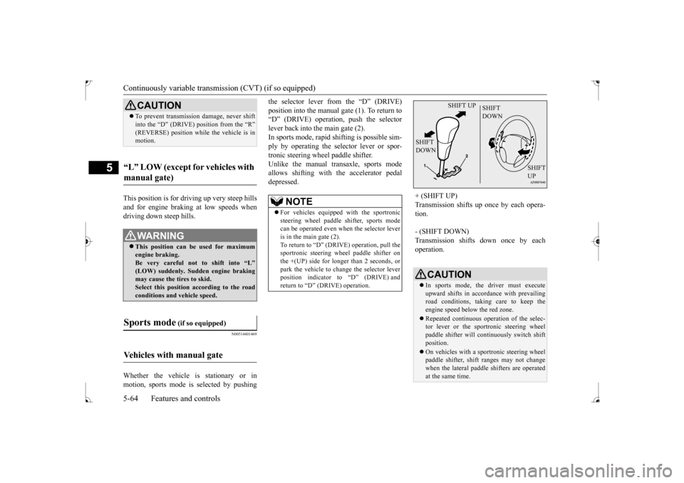
the selector lever from the “D” (DRIVE) position into the manual gate (1). To return to “D” (DRIVE) operation, push the selector lever back into the main gate (2).In sports mode, rapid shifting is possible sim- ply by operating the selector lever or spor- tronic steering wheel paddle shifter.Unlike the manual transaxle, sports mode allows shifting with the accelerator pedal depressed.
CAUTION To prevent transmission damage, never shift into the “D” (DRIVE) position from the “R” (REVERSE) position while
the vehicle is in
motion.
“L” LOW (except for vehicles with manual gate)
WA R N I N G This position can be used for maximum engine braking.Be very careful not to shift into “L” (LOW) suddenly. Sudden engine braking may cause the tires to skid.Select this position according to the road conditions and vehicle speed.
Sports mode
(if so equipped)
Vehicles with manual gate
NOTE
For vehicles equipped with the sportronic steering wheel paddle shifter, sports modecan be operated even when the selector lever is in the main gate (2). To return to “D” (DRIVE) operation, pull thesportronic steering wheel paddle shifter on the +(UP) side for longer than 2 seconds, or park the vehicle to change the selector leverposition indicator to “D” (DRIVE) and return to “D” (DRIVE) operation.
+ (SHIFT UP) Transmission shifts up once by each opera- tion. - (SHIFT DOWN) Transmission shifts down once by each operation.
CAUTION In sports mode, the driver must execute upward shifts in accordance with prevailing road conditions, taking care to keep theengine speed below the red zone. Repeated continuous operation of the selec- tor lever or the sportronic steering wheel paddle shifter will continuously switch shift position. On vehicles with a sportronic steering wheel paddle shifter, shift ranges may not changewhen the lateral paddle shifters are operated at the same time.
SHIFT UP
SHIFT DOWN
SHIFT DOWN
SHIFT UP
BK0237700US.bo
ok 64 ページ 2016年4月15日 金曜日 午前11時28分
Page 130 of 385
Continuously variable transmission (CVT) (if so equipped)
Features and controls 5-65
5
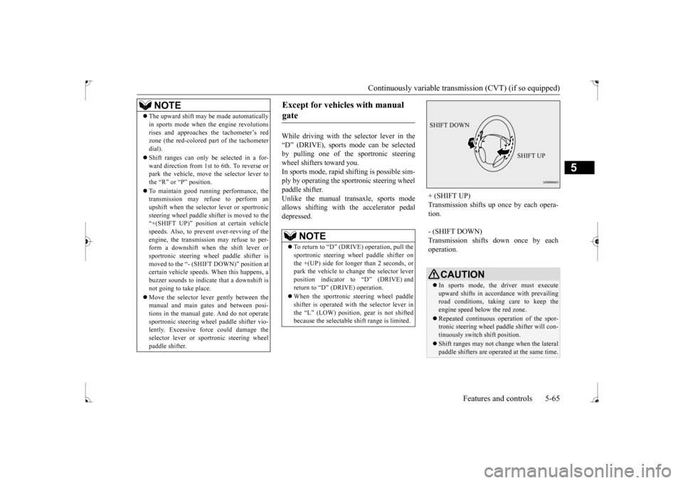
While driving with the selector lever in the “D” (DRIVE), sports mode can be selected by pulling one of the sportronic steeringwheel shifters toward you. In sports mode, rapid
shifting is possible sim-
ply by operating the sportronic steering wheelpaddle shifter.Unlike the manual transaxle, sports mode allows shifting with the accelerator pedal depressed.
NOTE
The upward shift may be made automatically in sports mode when the engine revolutions rises and approaches the tachometer’s red zone (the red-colored part of the tachometer dial). Shift ranges can only be selected in a for- ward direction from 1st to 6th. To reverse orpark the vehicle, move the selector lever to the “R” or “P” position. To maintain good running performance, the transmission may refuse to perform an upshift when the selector lever or sportronicsteering wheel paddle shifter is moved to the “+(SHIFT UP)” positi
on at certain vehicle
speeds. Also, to prevent over-revving of theengine, the transmission may refuse to per- form a downshift when the shift lever or sportronic steering wheel paddle shifter ismoved to the “- (SHIFT DOWN)” position at certain vehicle speeds. When this happens, a buzzer sounds to indicate that a downshift isnot going to take place. Move the selector lever gently between the manual and main gates and between posi- tions in the manual gate. And do not operate sportronic steering wheel paddle shifter vio-lently. Excessive force could damage the selector lever or sportronic steering wheel paddle shifter.
Except for vehicles with manual gate
NOTE
To return to “D” (DRIVE) operation, pull the sportronic steering wheel paddle shifter on the +(UP) side for longer than 2 seconds, orpark the vehicle to change the selector lever position indicator to “D” (DRIVE) and return to “D” (DRIVE) operation. When the sportronic steering wheel paddle shifter is operated with the selector lever inthe “L” (LOW) position, gear is not shifted because the selectable shift range is limited.
+ (SHIFT UP) Transmission shifts up once by each opera- tion. - (SHIFT DOWN) Transmission shifts down once by each operation.
CAUTION In sports mode, the driver must execute upward shifts in accordance with prevailing road conditions, taking care to keep theengine speed below the red zone. Repeated continuous operation of the spor- tronic steering wheel paddle shifter will con- tinuously switch shift position. Shift ranges may not change when the lateral paddle shifters are operated at the same time.
SHIFT DOWN
SHIFT UP
BK0237700US.bo
ok 65 ページ 2016年4月15日 金曜日 午前11時28分
Page 131 of 385
Continuously variable transm
ission (CVT) (if so equipped)
5-66 Features and controls
5
N00538800154
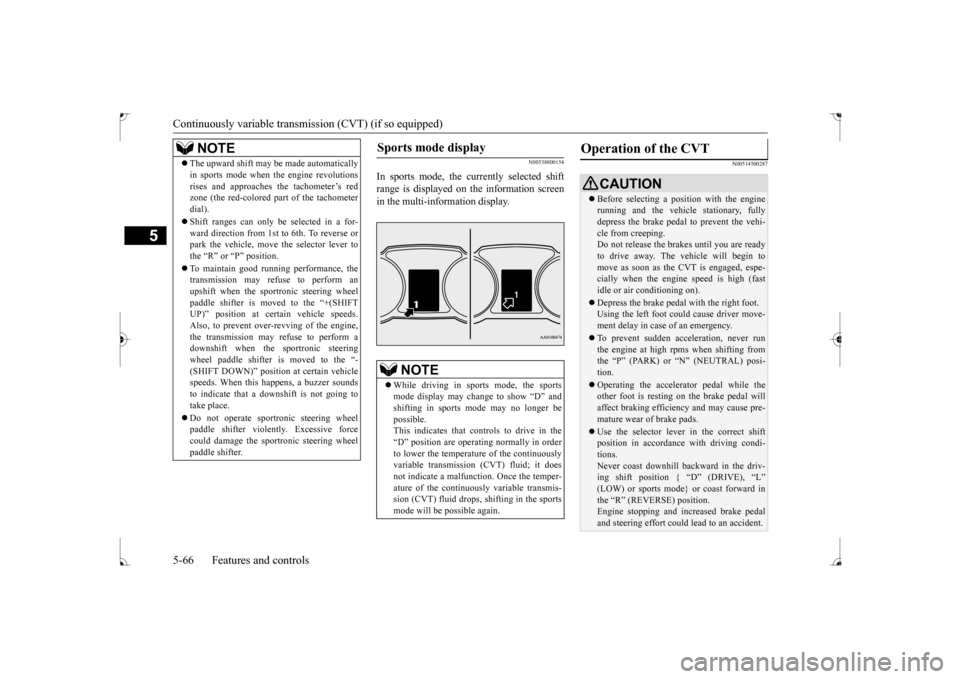
In sports mode, the currently selected shift range is displayed on the information screenin the multi-information display.
N00514500287
NOTE
The upward shift may be made automatically in sports mode when the engine revolutions rises and approaches the tachometer’s red zone (the red-colored part of the tachometer dial). Shift ranges can only be selected in a for- ward direction from 1st to 6th. To reverse orpark the vehicle, move the selector lever to the “R” or “P” position. To maintain good running performance, the transmission may refuse to perform an upshift when the sportronic steering wheelpaddle shifter is moved to the “+(SHIFT UP)” position at certain vehicle speeds. Also, to prevent over-revving of the engine,the transmission may refuse to perform a downshift when the sportronic steering wheel paddle shifter is moved to the “-(SHIFT DOWN)” position at certain vehicle speeds. When this happens, a buzzer sounds to indicate that a downshift is not going totake place. Do not operate sportronic steering wheel paddle shifter violently. Excessive force could damage the sportronic steering wheel paddle shifter.
Sports mode display
NOTE
While driving in sports mode, the sports mode display may change to show “D” and shifting in sports mode may no longer be possible.This indicates that controls to drive in the “D” position are operating normally in order to lower the temperature of the continuouslyvariable transmission (CVT) fluid; it does not indicate a malfunction. Once the temper- ature of the continuously variable transmis-sion (CVT) fluid drops, shifting in the sports mode will be possible again.
Operation of the CVT
CAUTION Before selecting a position with the engine running and the vehicle stationary, fully depress the brake pedal to prevent the vehi- cle from creeping.Do not release the brakes until you are ready to drive away. The vehicle will begin to move as soon as the CVT is engaged, espe-cially when the engine speed is high (fast idle or air conditioning on). Depress the brake pedal with the right foot. Using the left foot could cause driver move- ment delay in case of an emergency. To prevent sudden acceleration, never run the engine at high rpms when shifting fromthe “P” (PARK) or “N” (NEUTRAL) posi- tion. Operating the accelerator pedal while the other foot is resting on the brake pedal will affect braking efficiency and may cause pre-mature wear of brake pads. Use the selector lever in the correct shift position in accordance with driving condi- tions. Never coast downhill backward in the driv- ing shift position { “D” (DRIVE), “L” (LOW) or sports mode} or coast forward inthe “R” (REVERSE) position. Engine stopping and increased brake pedal and steering effort could lead to an accident.
BK0237700US.bo
ok 66 ページ 2016年4月15日 金曜日 午前11時28分
Page 135 of 385
All-wheel driving operation 5-70 Features and controls
5
N00530600169
Full-time 4WD vehicles are propelled by engine power distributed constantly andappropriately to all 4 wheels. Not only does this ensure enhanced handling on dry, paved roads but also permits bettertraction when driving on slippery, wet orsnow-covered roads and when moving out of mud. These vehicles, however, are not designedfor off-road use, and are unsuitable for driving on bumpy ground that may cause excessive strain.
Full-time 4WD vehicles
should be driven only under the same condi- tions as are suitable for ordinary front-wheel drive vehicles. Electronically controlled 4WD system vehi- cles are propelled by engine power distrib- uted constantly and appropriately to all 4 wheels. Not only does this ensure enhanced handling on dry, paved roads but also permits better
traction when driving on slippery, wet or snow-covered roads and when moving out of mud. These vehicles, however, are not designedfor off-road use, and are unsuitable for driving on bumpy ground that may cause excessive strain.
Electronically controlled
4WD system vehicles should be driven only under the same conditions as are suitable for ordinary front-wheel drive vehicles. When turning a sharp corner in “4WD LOCK” position at low speed, a slight differ- ence in steering may be experienced similarto feeling as if the brakes were applied. This is called tight corner braking and results from each of the four tires being at a different dis-tance from the corner. The phenomenon is typical of 4-wheel drive vehicles. If this occurs, either straighten out the steeringwheel, or change to “2WD” or “4WD AUTO” mode. Set the drive mode-selector to “4WD AUTO” conditions, and then gradually depress theaccelerator pedal for a smooth start.
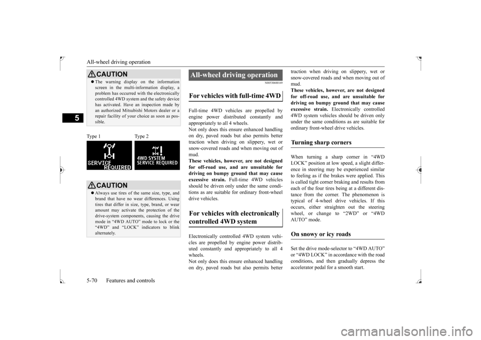
CAUTION The warning display on the information screen in the multi-information display, a problem has occurred with the electronically controlled 4WD system and the safety device has activated. Have an inspection made byan authorized Mitsubishi Motors dealer or a repair facility of your choice as soon as pos- sible.
Type 1 Type 2
CAUTION Always use tires of the same size, type, and brand that have no wear differences. Using tires that differ in size, type, brand, or wear amount may activate the protection of thedrive-system components, causing the drive mode in “4WD AUTO” mode to lock or the “4WD” and “LOCK” indicators to blinkalternately.
All-wheel driving operation For vehicles with full-time 4WD For vehicles with electronically controlled 4WD system
Turning sharp corners On snowy or icy roads
BK0237700US.bo
ok 70 ページ 2016年4月15日 金曜日 午前11時28分
Page 156 of 385
Multi-information display
Features and controls 5-91
5
N00554900137
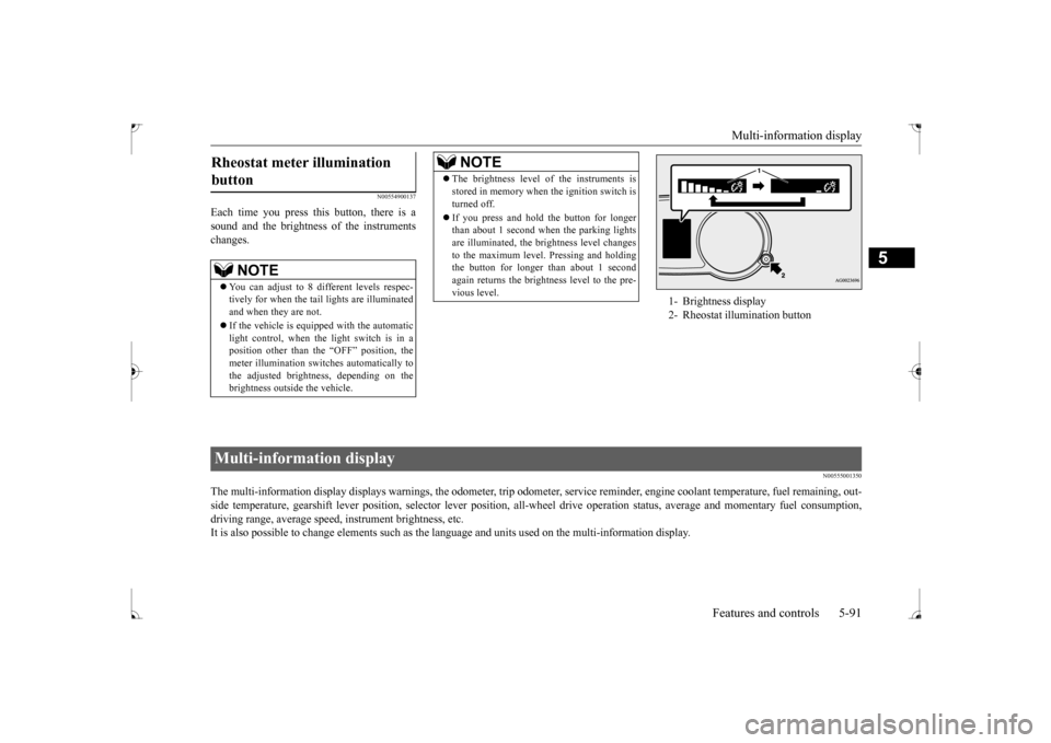
Each time you press this button, there is a sound and the brightness of the instruments changes.
N00555001350
The multi-information display displays warnings, the odometer, tr
ip odometer, service reminder, engine coolant temperature, fue
l remaining, out-
side temperature, gearshift lever position, selector lever pos
ition, all-wheel drive operation status, average and momentary fu
el consumption,
driving range, average speed, instrument brightness, etc. It is also possible to change elements such as the
language and units used on the multi-information display.
Rheostat meter illumination button
NOTE
You can adjust to 8 different levels respec- tively for when the tail lights are illuminated and when they are not. If the vehicle is equipped with the automatic light control, when the light switch is in a position other than the “OFF” position, themeter illumination switches automatically to the adjusted brightness, depending on the brightness outside the vehicle.
The brightness level of the instruments is stored in memory when the ignition switch is turned off. If you press and hold the button for longer than about 1 second when the parking lights are illuminated, the brightness level changes to the maximum level. Pressing and holdingthe button for longer than about 1 second again returns the brightness level to the pre- vious level.NOTE
1- Brightness display 2- Rheostat illumination button
Multi-information display
BK0237700US.bo
ok 91 ページ 2016年4月15日 金曜日 午前11時28分
Page 198 of 385
Turn signal lever
Features and controls 5-133
5
N00522601545
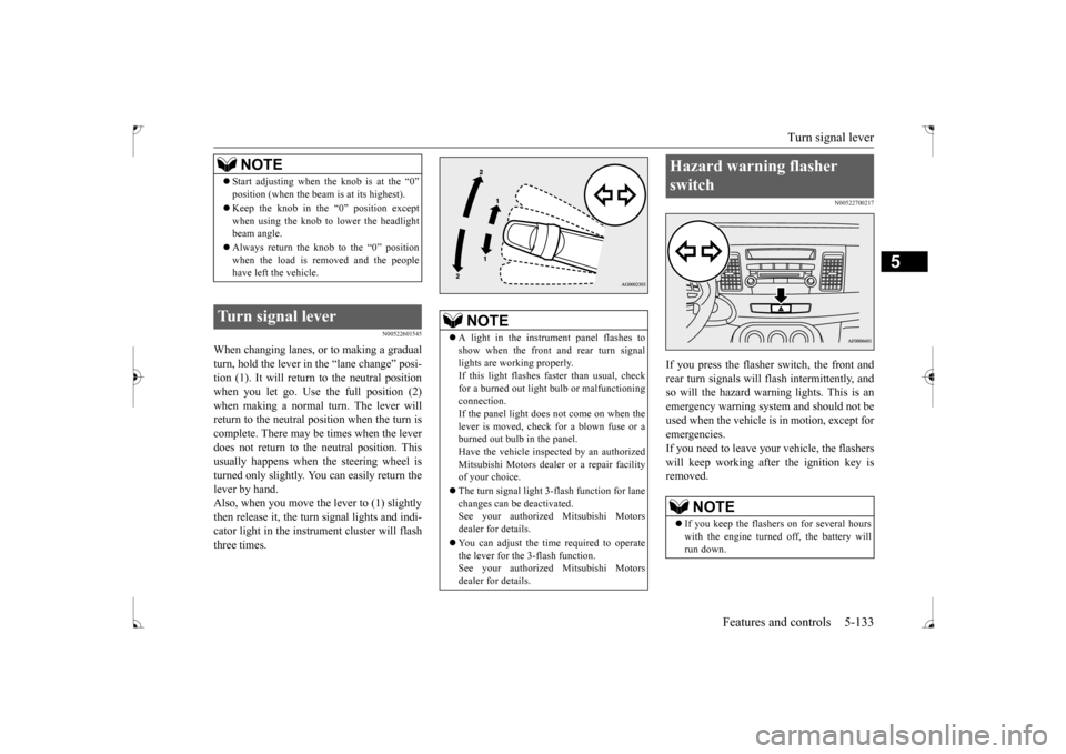
When changing lanes, or to making a gradual turn, hold the lever in
the “lane change” posi-
tion (1). It will return to the neutral positionwhen you let go. Use the full position (2) when making a normal turn. The lever will return to the neutral position when the turn iscomplete. There may be times when the lever does not return to the neutral position. This usually happens when the steering wheel isturned only slightly. You can easily return the lever by hand. Also, when you move the lever to (1) slightlythen release it, the turn signal lights and indi- cator light in the instrument cluster will flash three times.
N00522700217
If you press the flasher switch, the front andrear turn signals will flash intermittently, and so will the hazard warning lights. This is an emergency warning system and should not beused when the vehicle is in motion, except foremergencies. If you need to leave your vehicle, the flashers will keep working afte
r the ignition key is
removed.
NOTE
Start adjusting when the knob is at the “0” position (when the beam is at its highest). Keep the knob in the “0” position except when using the knob to lower the headlightbeam angle. Always return the knob to the “0” position when the load is removed and the people have left the vehicle.
Turn signal lever
NOTE
A light in the instrument panel flashes to show when the front and rear turn signal lights are working properly.If this light flashes faster than usual, check for a burned out light bulb or malfunctioning connection.If the panel light does not come on when the lever is moved, check for a blown fuse or a burned out bulb in the panel.Have the vehicle inspected by an authorized Mitsubishi Motors dealer or a repair facility of your choice. The turn signal light 3-flash function for lane changes can be deactivated.See your authorized Mitsubishi Motors dealer for details. You can adjust the time required to operate the lever for the 3-flash function. See your authorized Mitsubishi Motorsdealer for details.
Hazard warning flasher switch
NOTE
If you keep the flashers on for several hours with the engine turned off, the battery will run down.
BK0237700US.book
133 ページ 2016年4月15日 金曜日 午前11時28分
Page 217 of 385
Bluetooth® 2.0 interface (if so equipped) 5-152 Features and controls
5
6. The voice guide will say “Calling
You can redial the last number called, based on the history of dialed calls in the paired cel- lular phone. Use the following procedure to redial. 1. Press the SPEECH button. 2. Say “Redial.”
N00565700018
During a call, press the SPEECH button toenter voice recognition mode, then say“
N00565800019
If an incoming phone call is received while the ignition switch is in the “ACC” or “ON”position, the audio system will be automati- cally turned on and switched to the incoming call, even when the audio system was origi-nally off. The voice guide announcement for the incoming call will be output from the frontpassenger’s seat speaker.If the CD player or radio was playing when the incoming call was received, the audio sys- tem will mute the sound from the CD playeror radio and output only
the incoming call.
To receive the call, press the PICK-UP button on the steering wheel control switch.When the call is over,
the audio system will
return to its previous state.
N00565900010
At any time during a call, you can mute thevehicle microphone. Pressing the SPEECH button and then saying“Mute” during a call will turn ON the mute function and mute the microphone. Saying “Mute off” in the same way will turnoff the mute function and cancel the mute on the microphone.
NOTE
If the name you selected has matching data in the vehicle phonebook but no telephone number is registered under the selected loca- tion, the voice guide will say “{home/work/mobile/other} not found for
NOTE
When the confirmation function is on, the system will check if the name and location of the receiver are correct. If the name is cor- rect, answer “Yes.” To change the name or location to call,answer “No.” The system will return to Step 3.
RedialingSend function
Receiving calls
Mute function
BK0237700US.book
152 ページ 2016年4月15日 金曜日 午前11時28分
Page 310 of 385
How to change a tire
For emergencies 8-7
8
6. Get the jack, bar and wheel nut wrench ready.Refer to “Tools and jack” on page 8-5.
N00849600298
The compact spare tire is designed to savespace in the trunk. Its lighter weight makes iteasier to use if a flat tire occurs.
N00849701339
1. Lift up the luggage floor board.For front-wheel drive vehicles, pull theluggage floor board (A) rearward to release the hooks (B), and then lift it up.
NOTE
The chocks shown in the illustration do not come with your vehicle. It is recommended that you purchase chocks or blocks and keep them in the vehicle for use if needed. If chocks or blocks are not available, use stones or any other objects that are large enough to hold the wheel in position.
Spare tire information Compact spare tire
WA R N I N G Tires, including spare tire, degrade over time with age even when they are not being used. It is recommended that tiresover 6 years generally be replaced even if damage is not obvious.
CAUTION While the compact spare tire is stowed, the inflation pressure should be checked at least once a month to assure that it remains at the recommended inflation pressure. See the tire and loading information placard attached tothe driver’s door sill. Refer to “Tire and loading information plac- ard” on page 11-3. Driving with an improperly inflated tire can cause an accident. If you have no choice butto drive with an under-inflated tire, keep your speed down and avoid sudden steering or braking, if possible
. Inflate the tire to the
correct pressure as soon as possible. Refer to “Tire inflation pressures” on page 9-17. The compact spare tire should be used only temporarily. While the compact spare tire is being used, the tire pressure monitoring sys-tem will not function properly. Have the tire replaced or repaired at an authorized Mit- subishi Motors dealer or a repair facility ofyour choice as soon as possible. If your vehicle has aluminum type wheels, you can use the same wheel nuts on the com- pact spare tire wheel. Do not go over 50 mph (80 km/h) when driv- ing with the compact spare tire. Avoid fast starting and braking when driving with the compact spare tire.
Do not drive through automatic car washes and over obstacles that could possibly dam- age the underside of your vehicle. Because the compact spare tire is smaller than the original tire, there is less clearance betweenthe ground and your vehicle. Because the compact spare tire is designed only for your vehicle, do not use it on any other vehicle. Do not put the compact spare tire on a differ- ent wheel, and do not put standard tires, snow tires, wheel covers or trim rings on thecompact spare wheel. Otherwise, you could damage these parts or other parts on your vehicle. Do not use snow chain with your compact spare tire. Using a chain could cause damageto your vehicle and loss of the chains.
To remove the compact spare tire
CAUTION
BK0237700US.bo
ok 7 ページ 2016年4月15日 金曜日 午前11時28分