brake light MITSUBISHI LANCER EVOLUTION 2007 Service Repair Manual
[x] Cancel search | Manufacturer: MITSUBISHI, Model Year: 2007, Model line: LANCER EVOLUTION, Model: MITSUBISHI LANCER EVOLUTION 2007Pages: 1449, PDF Size: 56.82 MB
Page 100 of 1449

B-2
S
PWGEE
IGNITION SYSTEM
L.H. drive vehicles 82.......................
R.H. drive vehicles 83.......................
CHARGING SYSTEM 84...................
ENGINE CONTROL SYSTEM
L.H. drive vehicles 86.......................
R.H. drive vehicles 94.......................
COOLING SYSTEM 102...................
HEADLAMP
L.H. drive vehicles 103......................
R.H. drive vehicles 106......................
TAIL LAMP, POSITION LAMP, LICENCE
PLATE LAMP AND LIGHTING MONITOR
BUZZER
L.H. drive vehicles 110......................
R.H. drive vehicles 114......................
ROOM LAMP AND LUGGAGE
COMPARTMENT LAMP
L.H. drive vehicles 118......................
R.H. drive vehicles 121......................
REAR FOG LAMP
L.H. drive vehicles 124......................
R.H. drive vehicles 127......................
HEADLAMP LEVELING SYSTEM
L.H. drive vehicles 130......................
R.H. drive vehicles 132......................
TURN-SIGNAL LAMP AND HAZARD
WARNING LAMP
L.H. drive vehicles 134......................
R.H. drive vehicles 138......................
BACK-UP LAMP
L.H. drive vehicles 142......................
R.H. drive vehicles 143......................
STOP LAMP
L.H. drive vehicles 144......................
R.H. drive vehicles 145......................
HORN 146................................
METER AND GAUGE
L.H. drive vehicles 148......................
R.H. drive vehicles 152......................
FUEL WARNING LAMP 156...............
OIL PRESSURE WARNING LAMP 157.....
BRAKE WARNING LAMP 157.............
POWER WINDOWS
L.H. drive vehicles 158......................
R.H. drive vehicles 164......................
CENTRAL DOOR LOCKING SYSTEM
L.H. drive vehicles 170......................
R.H. drive vehicles 172......................
HEATER AND MANUAL AIR CONDITIONER
L.H. drive vehicles 174......................
R.H. drive vehicles 180......................
DEFOGGER 185..........................
WINDSHIELD WIPER AND WASHER
L.H. drive vehicles 186......................
R.H. drive vehicles 189......................
REMOTE CONTROLLED MIRROR
L.H. drive vehicles 192......................
R.H. drive vehicles 193......................
CLOCK 194..............................
CIGARETTE LIGHTER AND ASHTRAY
ILLUMINATION LAMP 195.................
AUDIO SYSTEM 196......................
Page 129 of 1449

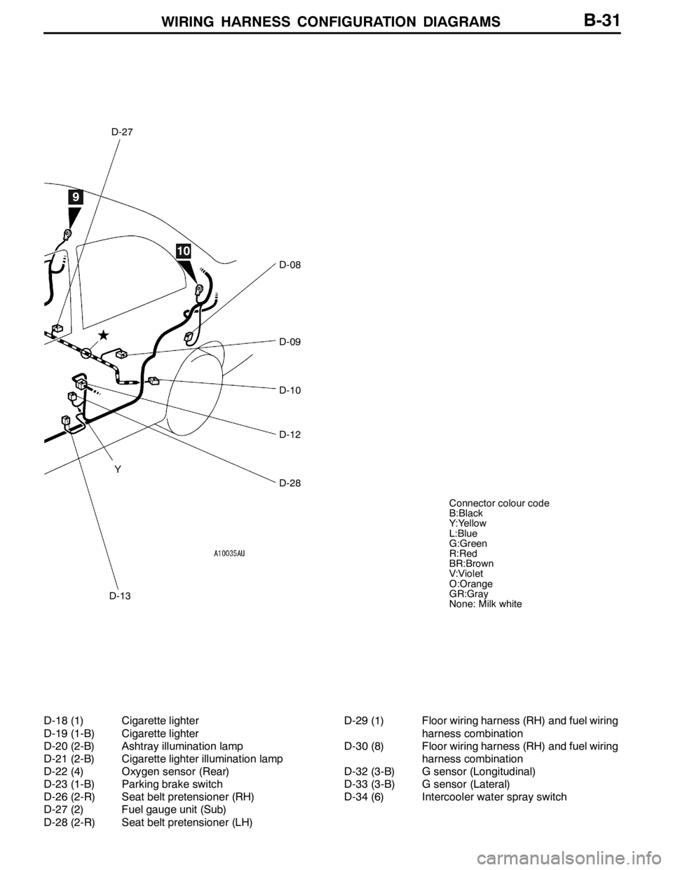
WIRING HARNESS CONFIGURATION DIAGRAMS
D-13
D-27
D-08
D-09
D-10
D-12
D-28 Y
9
10
Connector colour code
B:Black
Y:Yellow
L:Blue
G:Green
R:Red
BR:Brown
V:Violet
O:Orange
GR:Gray
None: Milk white
B-31
D-18 (1) Cigarette lighter
D-19 (1-B) Cigarette lighter
D-20 (2-B) Ashtray illumination lamp
D-21 (2-B) Cigarette lighter illumination lamp
D-22 (4) Oxygen sensor (Rear)
D-23 (1-B) Parking brake switch
D-26 (2-R) Seat belt pretensioner (RH)
D-27 (2) Fuel gauge unit (Sub)
D-28 (2-R) Seat belt pretensioner (LH)D-29 (1) Floor wiring harness (RH) and fuel wiring
harness combination
D-30 (8) Floor wiring harness (RH) and fuel wiring
harness combination
D-32 (3-B) G sensor (Longitudinal)
D-33 (3-B) G sensor (Lateral)
D-34 (6) Intercooler water spray switch
Page 131 of 1449

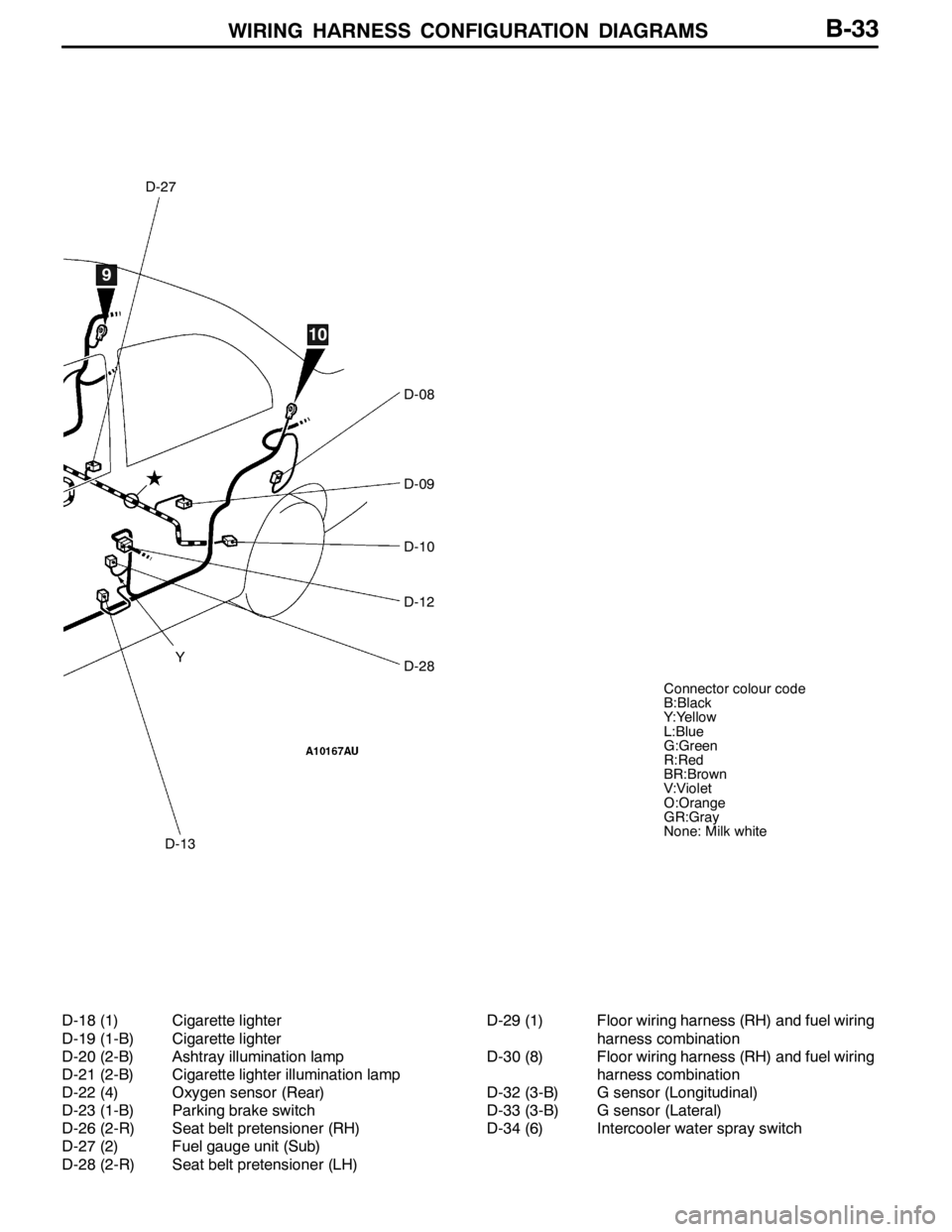
WIRING HARNESS CONFIGURATION DIAGRAMS
D-27
D-13
D-08
D-09
D-10
D-12
D-28
9
10
Y
Connector colour code
B:Black
Y:Yellow
L:Blue
G:Green
R:Red
BR:Brown
V:Violet
O:Orange
GR:Gray
None: Milk white
B-33
D-18 (1) Cigarette lighter
D-19 (1-B) Cigarette lighter
D-20 (2-B) Ashtray illumination lamp
D-21 (2-B) Cigarette lighter illumination lamp
D-22 (4) Oxygen sensor (Rear)
D-23 (1-B) Parking brake switch
D-26 (2-R) Seat belt pretensioner (RH)
D-27 (2) Fuel gauge unit (Sub)
D-28 (2-R) Seat belt pretensioner (LH)D-29 (1) Floor wiring harness (RH) and fuel wiring
harness combination
D-30 (8) Floor wiring harness (RH) and fuel wiring
harness combination
D-32 (3-B) G sensor (Longitudinal)
D-33 (3-B) G sensor (Lateral)
D-34 (6) Intercooler water spray switch
Page 364 of 1449

INDEX - In order of connector No.C-8
Wiring diagram
page Circuit diagram page Parts name Connector
No.
CC-223Fuel pump relay 1B-54,55,87,95B-23,29
C-224Power window relayB-54,55,158,159,165B-23,29
C-225No connectionB-54,55,78B-23,29
C-226ETACS-ECUB-54,55,105,108,112,113,116,117,118,
119,120,121,122,123,125,126,128,
129,134,136,137,138,140,141,158,
164,165, 170,171,172,173,188,189B-23,29
C-227ETACS-ECUB-125,128,170,172B-23,29
C-228ETACS-ECUB-105,108,112,113,116,117,118,119,
122,123,125,126,128,129,136,137,
140,141,158,159,164,165,170,171,
172,173, 188,189,258B-23,29
C-230Steering wheel sensorB-202,210,218,226,236,246B-23,29
DD-01Door switch (Front:RH)B-108,116,120,121,164B-30,32
D-02Floor wiring harness (RH) and rear door
wiring harness (RH) combinationB-160,166,171,173B-30,32
D-03Room lampB-118,122B-30,32
D-04Wheel speed sensor (Rear:RH)
D-05Rear room lampB-118,122B-30,32
D-06Door switch (Rear:RH)B-120,121B-30,32
D-08Door switch (Rear:LH)B-120,121B-30,32
D-09Fuel pump and fuel gauge unit (Main)B-93,101,148,152,156B-30,32
D-10Wheel speed sensor (Rear:LH)
D-12Floor wiring harness (LH) and rear door
wiring harness (LH) combinationB-161,167,171,173B-30,32
D-13Door switch (Front:LH)B-105,112,120,121,158B-30,32
D-15Instrument panel wiring harness and
console wiring harness combinationB-195B-31,32
D-18Cigarette lighterB-195B-31,33
D-19Cigarette lighterB-195B-31,33
D-20Ashtray illumination lampB-195B-31,33
D-21Cigarette lighter illumination lampB-195B-31,33
D-22Oxygen sensor (Rear)B-88,96B-31,33
D-23Parking brake switchB-157,201,209,213,221,232,242B-31,33
D-26Seat belt pretensioner (RH)B-249,251B-31,33
Page 367 of 1449

INDEX - In order of parts nameC-11
INDEX
In order of parts name
Parts nameConnector
No.Circuit diagram pageWiring diagram
page
4WD-ECU
219,220,221,222,223,224,226,227,
228,230,231,232,234,236,237,238,
240,241,242,244, 246,247B-19,25
4WD-ECU
221,224,225,227,228,229,232,234,
235,237,238,239,242,244,245,247B-19,25
AA/C compressorA-47B-178,184B-7,9
A/C compressor relayB-12XB-73,178,184B-10,14
A/C-ECU or heater control unitC-32B-175,181,185B-19,25
ABS-ECUB-123B-198,200,201,202,203,204,205,206,
208,209,210,211,229,232,233,239,
242,243B-13,17
ACD mode changeover switchC-142B-214,222,230,240B-21,27
Air bag module (squib)
Air bag module (squib)
Air flow sensorB-31B-90,98B-11,15
AlternatorB-21B-84B-11,15
AlternatorB-22B-84B-11,15
Ashtray illumination lampD-20B-195B-31,33
BBack-up lamp switchB-108B-142,143B-12,16
Blower motorC-14B-174,180B-18,24
Blower relayC-215B-54,55,174,180B-23,29
Blower switchC-131B-174,180B-21,27
Brake fluid level switchB-04B-157B-10,14
CCamshaft position sensorB-116B-88,96B-12,16
Cigarette lighterD-18B-195B-31,33
Cigarette lighterD-19B-195B-31,33
Cigarette lighter illumination lampD-21B-195B-31,33
ClockC-04B-194B-18,24
Clock spring
Clock spring
Page 449 of 1449

ENGINE -Engine Assembly11A-43
ENGINE ASSEMBLY
REMOVAL AND INSTALLATION
Caution
1. If the vehicle is equipped with the Brembo disc brake, during maintenance, take care not to
contact the parts or tools to the caliper because the paint of caliper will be scratched.
2. Tightening sections indicated in the mark (*) should be finally tightened with engine weight
applied on the body after lightly tightening.
Pre-removal and Post-installation Operation
DFuel Outflow Preventive Operation (Refer to GROUP 13A - On-vehicle Service.)
DFuel Leak Check
DRemoval and Installation of Hood (Refer to GROUP 42.)
DRemoval and Installation of Strut Tower Bar (Refer to GROUP 42.)
DRemoval and Installation of Under Cover (Refer to GROUP 51 - Front Bumper.)
DRemoval and Installation of Side Cover.
DDrive Belt Tension Check (Refer to P.11A - 7.)
DAccelerator Cable Adjustment (Refer to GROUP 17 - On-vehicle Service.)
DDrainage and Refilling Engine Oil(Refer to GROUP 12 - On-vehicle Service.)
DDrainage and Refilling of Engine Coolant (Refer to GROUP 14 - On-vehicle Service.)
DAir Cleaner Removal and Installation (Refer to GROUP 15)
DRemoval and Installation of Air Pipe C, Air Pipe B and Air Hose A (Refer to GROUP 15 - Intercooler.)
DBattery and Battery Tray Removal and Installation
DRemoval and Installation of Center Cover (Refer to P.11A - 17.)
DRemoval and Installation of Accelerator Cable (Refer to GROUP 17.)
DRemoval and Installation of Radiator (Refer to GROUP 14.)
DRemoval and Installation of Crossmember Bar (Refer to GROUP 32 - Engine Roll Stopper, Centermember.)
DRemoval and Installation of Front Exhaust Pipe (Refer to GROUP 15.)
DRemoval and Installation of Air Outlet Fitting (Refer to GROUP 15 - Exhaust manifold.)
Page 1050 of 1449

BASIC BRAKE SYSTEM -On-vehicle Service35A-8
2. If the brake pedal play is not within the standard value,
check the following, and adjust or replace if necessary:
DExcessive play between the brake pedal and the clevis
pin, or between the clevis pin and the brake booster
operating rod
DBrake pedal height
DInstallation position of the stop lamp switch, etc.
CLEARANCE BETWEEN BRAKE PEDAL AND FLOOR
BOARD
1. Turn up the carpet etc. under the brake pedal.
2. Start the engine, depress the brake pedal with
approximately 500 N of force, and measure the clearance
between the brake pedal and the floorboard.
Standard value (C): 90 mm or more
3. If the clearance is outside the standard value, check for
air trapped in the brake line and thickness of the disc
brake pad and dragging in the parking brake.
Adjust and replace defective parts as required.
4. Return the carpet, etc.
BRAKE BOOSTER OPERATING TEST
For simple checking of the brake booster operation, carry
out the following tests:
1. Run the engine for one or two minutes, and then stop
it.
If the pedal depresses fully the first time but gradually
becomes higher when depressed succeeding times, the
booster is operating properly. If the pedal height remains
unchanged, the booster is defective.
2. With the engine stopped, step on the brake pedal several
times.
Then start the engine while the brake pedal is stepped
on.
If the pedal moves downward slightly, the booster is in
good condition. If there is no change, the booster is
defective.
3. With the engine running, step on the brake pedal and
then stop the engine.
Hold the pedal depressed for 30 seconds. If the pedal
height does not change, the booster is in good condition.
If the pedal rises, the booster is defective.
If the above three tests are okay, the booster performance
can be determined as good.
If one of the above three tests is not okay at least, the check
valve, vacuum hose, or booster will be defective.
C
Good No good
When engine is
stoppedWhen engine is
started
GoodNo good
Page 1144 of 1449

STEERING - Power Steering Oil Pump/Power Steering Oil Hoses37A-30
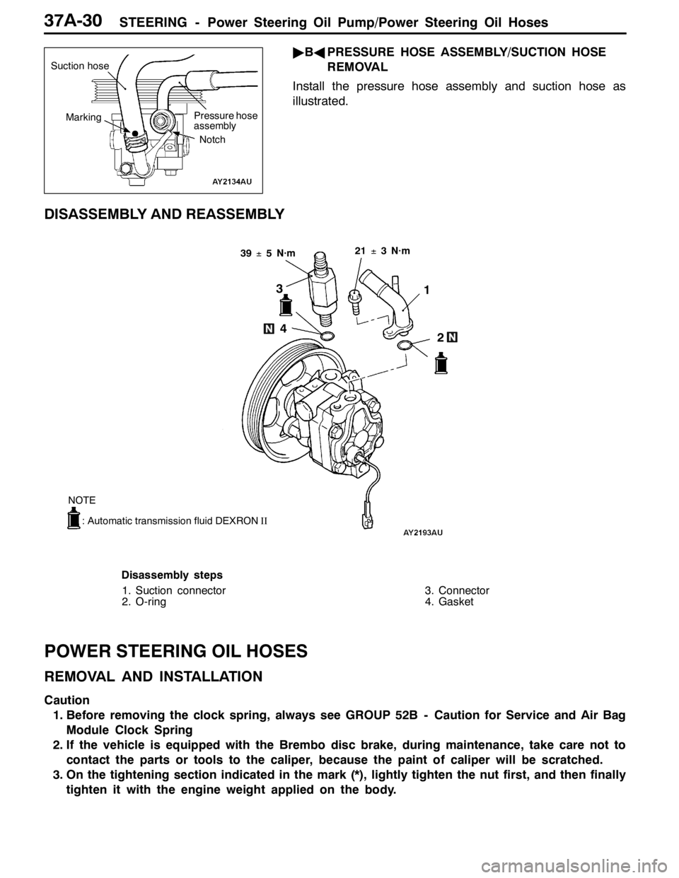
"BAPRESSURE HOSE ASSEMBLY/SUCTION HOSE
REMOVAL
Install the pressure hose assembly and suction hose as
illustrated.
DISASSEMBLY AND REASSEMBLY
21±3 N·m
3
4
2 1
39±5 N·m
: Automatic transmission fluid DEXRONII
NOTE
Disassembly steps
1. Suction connector
2. O-ring3. Connector
4. Gasket
POWER STEERING OIL HOSES
REMOVAL AND INSTALLATION
Caution
1. Before removing the clock spring, always see GROUP 52B - Caution for Service and Air Bag
Module Clock Spring
2. If the vehicle is equipped with the Brembo disc brake, during maintenance, take care not to
contact the parts or tools to the caliper, because the paint of caliper will be scratched.
3. On the tightening section indicated in the mark (*), lightly tighten the nut first, and then finally
tighten it with the engine weight applied on the body.
Suction hose
Pressure hose
assembly
Marking
Notch