water pump MITSUBISHI LANCER EVOLUTION 2007 Service Repair Manual
[x] Cancel search | Manufacturer: MITSUBISHI, Model Year: 2007, Model line: LANCER EVOLUTION, Model: MITSUBISHI LANCER EVOLUTION 2007Pages: 1449, PDF Size: 56.82 MB
Page 121 of 1449
WIRING HARNESS CONFIGURATION DIAGRAMS
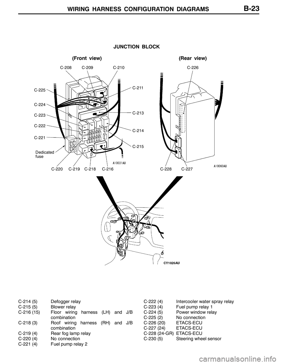
JUNCTION BLOCK
(Front view)(Rear view)
Dedicated
fuse
C-208C-209C-210C-226
C-220C-219C-218C-216C-228C-227
C-211
C-213
C-214
C-215
C-225
C-224
C-223
C-222
C-221
B-23
C-214 (5) Defogger relay
C-215 (5) Blower relay
C-216 (15) Floor wiring harness (LH) and J/B
combination
C-218 (3) Roof wiring harness (RH) and J/B
combination
C-219 (4) Rear fog lamp relay
C-220 (4) No connection
C-221 (4) Fuel pump relay 2C-222 (4) Intercooler water spray relay
C-223 (4) Fuel pump relay 1
C-224 (5) Power window relay
C-225 (2) No connection
C-226 (20) ETACS-ECU
C-227 (24) ETACS-ECU
C-228 (24-GR) ETACS-ECU
C-230 (5) Steering wheel sensor
Page 127 of 1449
WIRING HARNESS CONFIGURATION DIAGRAMS
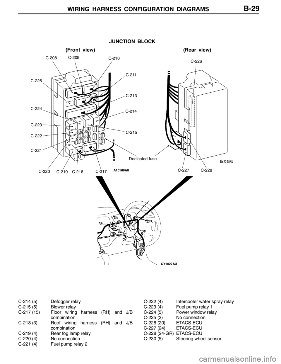
JUNCTION BLOCK
(Front view)(Rear view)
Dedicated fuse
C-226C-208C-209C-210
C-211
C-213
C-214
C-215
C-227C-228C-217C-218C-219C-220
C-222
C-221
C-223
C-224
C-225
B-29
C-214 (5) Defogger relay
C-215 (5) Blower relay
C-217 (15) Floor wiring harness (RH) and J/B
combination
C-218 (3) Roof wiring harness (RH) and J/B
combination
C-219 (4) Rear fog lamp relay
C-220 (4) No connection
C-221 (4) Fuel pump relay 2C-222 (4) Intercooler water spray relay
C-223 (4) Fuel pump relay 1
C-224 (5) Power window relay
C-225 (2) No connection
C-226 (20) ETACS-ECU
C-227 (24) ETACS-ECU
C-228 (24-GR) ETACS-ECU
C-230 (5) Steering wheel sensor
Page 138 of 1449
SINGLE PART INSTALLATION POSITION -Relay
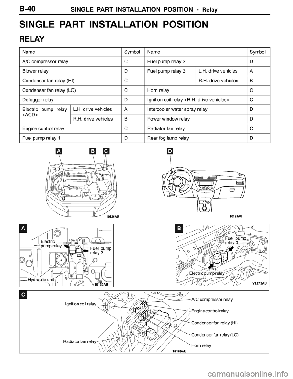
A
Electric
pump relay
Hydraulic unit
Fuel pump
relay 3
B
Electric pump relay
Fuel pump
relay 3
C
Ignition coil relay
Radiator fan relay
A/C compressor relay
Engine control relay
Condenser fan relay (HI)
Condenser fan relay (LO)
Horn relay
B-40
SINGLE PART INSTALLATION POSITION
RELAY
NameSymbolNameSymbol
A/C compressor relayCFuel pump relay 2D
Blower relayDFuel pump relay 3L.H. drive vehiclesA
Condenser fan relay (HI)CR.H. drive vehiclesB
Condenser fan relay (LO)CHorn relayC
Defogger relayDIgnition coil relay
Electric pump relay
L.H. drive vehiclesAIntercooler water spray relayD
Engine control relayCRadiator fan relayC
Fuel pump relay 1DRear fog lamp relayD
ABCD
Page 139 of 1449
SINGLE PART INSTALLATION POSITION -Relay/ECU
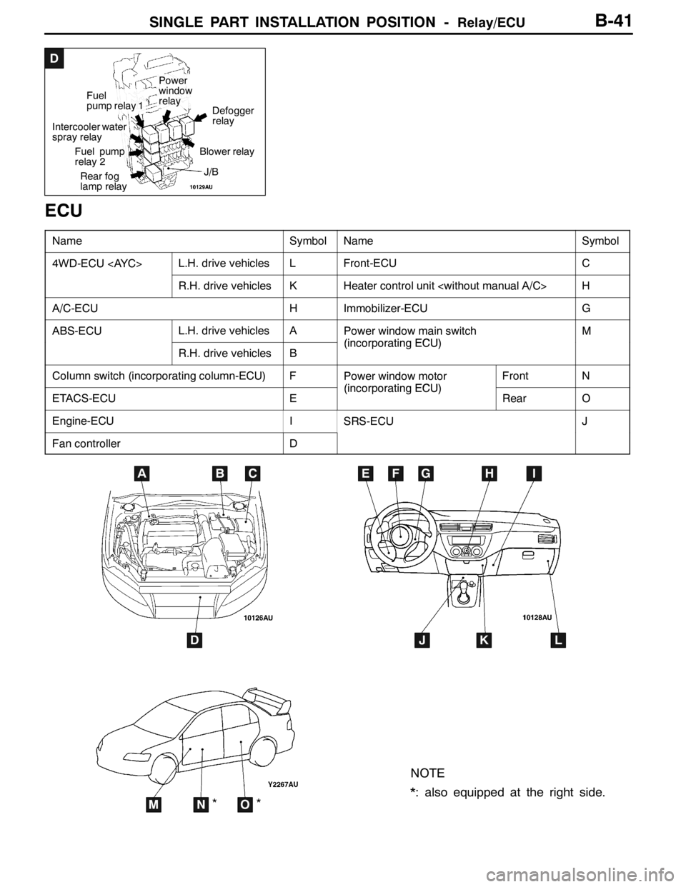
D
Intercooler water
spray relay
Fuel pump
relay 2
Rear fog
lamp relay
Fuel
pump relay 1
Power
window
relay
Defogger
relay
Blower relay
J/B
B-41
ECU
NameSymbolNameSymbol
4WD-ECU
R.H. drive vehiclesKHeater control unit
A/C-ECUHImmobilizer-ECUG
ABS-ECUL.H. drive vehiclesAPower window main switch
(incorporatingECU)
M
R.H. drive vehiclesB(incorporating ECU)
Column switch (incorporating column-ECU)FPower window motor
(incorporatingECU)
FrontN
ETACS-ECUE(incorporating ECU)RearO
Engine-ECUISRS-ECUJ
Fan controllerD
NOTE
*: also equipped at the right side.
ABC
D
EFGHI
JKL
MNO**
Page 153 of 1449
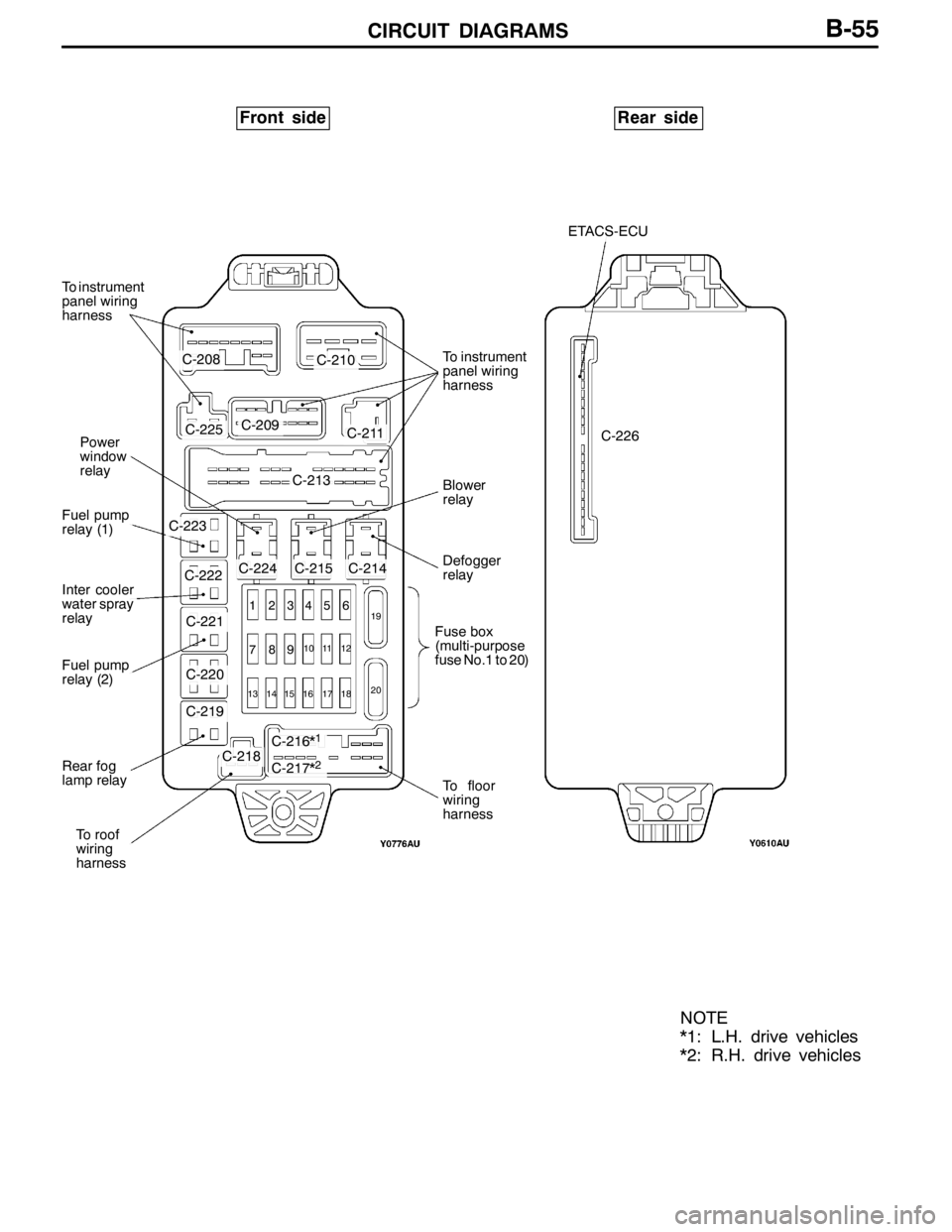
CIRCUIT DIAGRAMSB-55
Front sideRear side
To instrument
panel wiring
harness
Power
window
relay
Fuel pump
relay (1)
Fuel pump
relay (2)
Rear fog
lamp relay
To roof
wiring
harness
To instrument
panel wiring
harness
Blower
relay
Defogger
relay
Fuse box
(multi-purpose
fuse No.1 to 20)
To floor
wiring
harness
ETACS-ECU
NOTE
*1: L.H. drive vehicles
*2: R.H. drive vehicles
C-208C-210
C-211C-209C-225
C-213
C-223
C-224C-215C-214C-222
C-221
C-220
C-219
C-218C-216*1
C-217*2
1 23456
789
10 11 12
13 14 15 16 17 1819
20
C-226
Inter cooler
water spray
relay
Page 167 of 1449

CIRCUIT DIAGRAMSB-69
DEDICATED FUSE
Power supply
circuitNo.Rated
capacity (A)Identification
colourCircuit
Battery/alternator
(FusiblelinkNo6)
115BlueSpare connectors
(FusiblelinkNo.6)210RedHorn relay
320YellowEngine control relay and ignition control relay
410RedA/C compressor
515BlueABS-ECU, 4WD-ECU, high-mounted stop lamp and rear
combination lamp
630GreenCondenser fan motor
77.5BrownAlternator
810RedETACS-ECU
9---
1015BlueFuel pump
Front-ECU
(Headlamprelay:
1110RedHeadlamp
(Headlamp relay:
HI)1210RedHeadlamp
Front-ECU
(Headlamprelay:
1310RedFront combination lamp
(Headlamp relay:
LO)1410RedFront combination lamp
Front-ECU
(Tail lamp relay)157.5BrownHeater control unit or A/C-ECU, clock, combination
meter, fog lamp switch, hazard warning switch, radio,
rear combination lamp, headlamp leveling switch, front
combination lamp, cigarette lighter illumination lamp,
ashtray illumination lamp, ACD mode changeover switch
and inter cooler water splay switch
167.5BrownFront combination lamp, licence plate lamp and rear
combination lamp
Ignition switch
(ACC)1710RedClock
Battery/alternator
(Fusible link No. 6)1810RedEngine-ECU, ETACS-ECU, front-ECU and combination
meter
-19---
Fusible link No. 52120YellowIntercooler water splay
-22---
Ignition switch
(IG2)23---
-24---
Battery/alternator
(Fusible link No. 6)2530GreenCondenser fan motor
Page 169 of 1449

CIRCUIT DIAGRAMSB-71
MULTI-PURPOSE FUSE (In junction block)
Power supply
circuitNo.Rated
capacity (A)Identification
colourCircuit
Ignition
switch
IG1110RedIgnition coil
switch
27.5BrownColumn switch, combination meter, ETACS-ECU,
SRS-ECU, vehicle speed sensor and ACD mode
changeover switch
37.5BrownETACS-ECU and SRS-ECU
4---
IG257.5BrownA/C compressor relay, A/C-ECU, blower relay,
condenser fan relay, defogger relay, front-ECU,
4WD-ECU, steering wheel sensor and inter cooler
water splay relay
Multi-purpose fuse
No. 20 (Defogger
relay)6---
Ignition
switch
ACC720YellowFront-ECU and windshield wiper motor
switch
IG187.5BrownEngine-ECU and fuel pump relay (1) and fuel pump
relay (2)
ACC915BlueCigarette lighter
10---
117.5BrownA/C-ECU and remote controlled mirror switch
IG2127.5BrownABS-ECU, G-sensor (longitudinal) and G-sensor
(lateral)
ACC13---
14---
Fusible link No. 1
Battery/alternator
1515BlueDiagnosis connector
Battery/alternator
1610RedRear fog lamp relay
1710RedETACS-ECU
18---
1930GreenBlower motor and resistor
2030GreenDefogger
Page 363 of 1449

INDEX - In order of connector No.C-7
Wiring diagram
page Circuit diagram page Parts name Connector
No.
CC-207Air bag module (squib)
C-208Instrument panel wiring harness and
J/B combinationB-54,55,126,129,256B-22,28
C-209Instrument panel wiring harness and
J/B combinationB-54,55,87,95,104,105,107,108,110,
111,112,115,116,118,122,125,128,134,
136,137,138,139,140,141,142,143,
149,153,158,164,170,172,174,180,
186,187,188,189,190,191,189,198,
202,206,210,218,222,226,236,240,
246,256B-22,28
C-210Instrument panel wiring harness and
J/B combinationB-54,55,76,77,78,82,83,84,87,95,104,
107,111,112,115,116,118,122,125,128,
136,137,140,141,142,143,149,153,
157,158,159,164,165,170,172,174,
180,185,186,187,190,191,192,193,
195,198,200,202,206,208,210,212,
213,214,218,220,221,222,226,228,
229,230,236,238,239,240,246,248,
250, 256B-22,28
C-211Instrument panel wiring harness and
J/B combinationB-54,55,78,92,100,105,108,113,117,
119,123,125,128,137,141,150,154,
158,164,170,172,174,180,185,188,
189,204,205,219,227,237,247,248,
250,252,254B-22,28
C-213Instrument panel wiring harness and
J/B combinationB-54,55,78,82,83,84,87,92,95,100,
104,105,107,108,110,112,113,115,
116,117,119,120,121,123,125,126,
128,129,135,136,137,139,140,141,
149,150,153,154,157,158,164,170,
171,172,173,174,180,185,187,188,
189,191,192,193,195,198,200,204,
205,206,208,212,213,214,219,220,
221,222,227,228,229,230,237,238,
239,240,247,248, 250,252,254,256B-22,28
C-214Defogger relayB-54,55,78,185B-23,29
C-215Blower relayB-54,55,174,180B-23,29
C-216Floor wiring harness (LH) and J/B
combination
158,171,185B-23
C-217Floor wiring harness (RH) and J/B
combination
164, 173,185B-29
C-218Roof wiring harness (RH) and J/B
combinationB-54,55,118,119,122,123B-23,29
C-219Rear fog lamp relayB-54,55,126,129B-23,29
C-220No connectionB-54,55B-23,29
C-221Fuel pump relay 2B-54,55,87,95B-23,29
C-222Intercooler water spray relayB-54,55,256B-23,29
Page 414 of 1449
ENGINE -On-vehicle Service11A-8
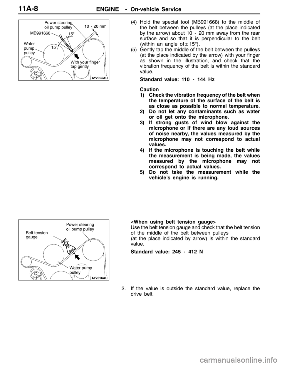
(4) Hold the special tool (MB991668) to the middle of
the belt between the pulleys (at the place indicated
by the arrow) about 10 - 20 mm away from the rear
surface and so that it is perpendicular to the belt
(within an angle of±15°).
(5) Gently tap the middle of the belt between the pulleys
(at the place indicated by the arrow) with your finger
as shown in the illustration, and check that the
vibration frequency of the belt is within the standard
value.
Standard value: 110 - 144 Hz
Caution
1) Check the vibration frequency of the belt when
the temperature of the surface of the belt is
as close as possible to normal temperature.
2) Do not let any contaminants such as water
or oil get onto the microphone.
3) If strong gusts of wind blow against the
microphone or if there are any loud sources
of noise nearby, the values measured by the
microphone may not correspond to actual
values.
4) If the microphone is touching the belt while
the measurement is being made, the values
measured by the microphone may not
correspond to actual values.
5) Do not take the measurement while the
vehicle’s engine is running.
Use the belt tension gauge and check that the belt tension
of the middle of the belt between pulleys
(at the place indicated by arrow) is within the standard
value.
Standard value: 245 - 412 N
2. If the value is outside the standard value, replace the
drive belt.Power steering
oil pump pulley
Water
pump
pulley
MB991668
10 - 20 mm
15°
15°
With your finger
tap gently
Belt tension
gauge
Power steering
oil pump pulley
Water pump
pulley
Page 440 of 1449

ENGINE -Timing Belt and Timing Belt B11A-34
TIMING BELT AND TIMING BELT B
REMOVAL AND INSTALLATION
Caution
If the vehicle is equipped with the Brembo disc brake, during maintenance, take care not to contact
the parts or tools to the caliper because the paint of caliper will be scratched.
Pre-removal and Post-installation Operation
DUnder Cover Removal and Installation (Refer to GROUP 51 - Front Bumper.)
DSide Cover Removal and Installation
DDrive Belt Tension Check (Refer to P.11A-7.)
DCrankshaft Pulley Removal and Installation (Refer to P.11A-15.)
DCrossmember Bar Removal and Installation (Refer to GROUP 32 - Engine Roll Stopper, Centermember.)
DFront Exhaust Pipe Removal and Installation (Refer to GROUP 15.)
DEngine Mounting Removal and Installation (Refer to GROUP 32.)
1
2
3
4 5
67 89
10
11±1 N·m
8.8±1.0 N·m
44±10 N·m
24±4 N·m
11±1 N·m
9.0±1.0 N·m64±5 N·m 11±1 N·m48±5 N·m21±4 N·m
23±3 N·m
11
35±6 N·m
Removal steps
1. Timing belt front upper cover
2. Water pump pulley
3. Timing belt front center cover
4. Idler pulley
5. Drive belt auto-tensioner
6. Timing belt front lower cover"GADTiming belt tension adjustment
AA""FA7. Timing belt
"EA8. Tensioner pulley
9. Tensioner arm
"DA10. Auto-tensioner
11. Idler pulley