Ac switch MITSUBISHI LANCER EVOLUTION 2015 10.G User Guide
[x] Cancel search | Manufacturer: MITSUBISHI, Model Year: 2015, Model line: LANCER EVOLUTION, Model: MITSUBISHI LANCER EVOLUTION 2015 10.GPages: 338, PDF Size: 43.12 MB
Page 38 of 338
Child restraint systems
Seat and restraint systems 4-13
4
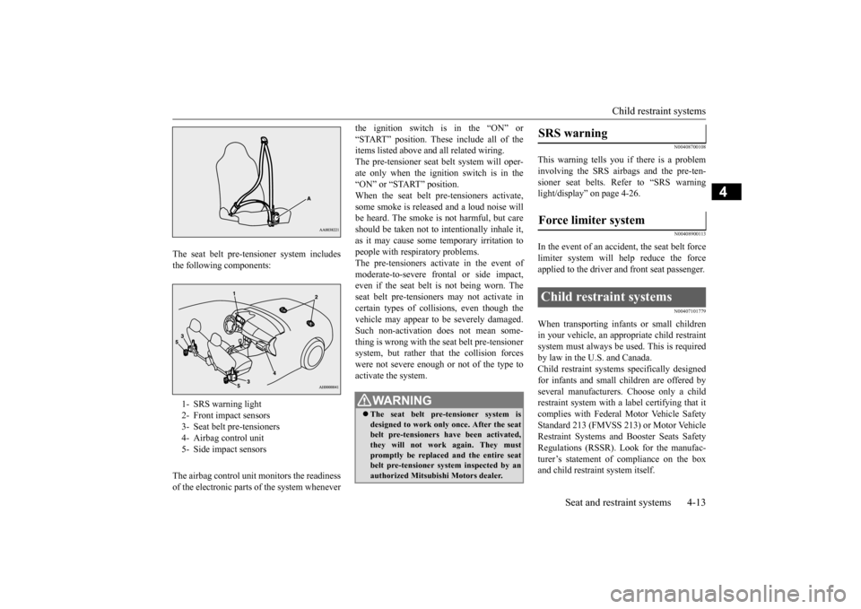
The seat belt pre-tensioner system includes the following components: The airbag control unit monitors the readiness of the electronic parts of the system whenever
the ignition switch is in the “ON” or “START” position. These include all of the items listed above and all related wiring. The pre-tensioner seat belt system will oper-ate only when the ignition switch is in the “ON” or “START” position. When the seat belt pre-tensioners activate,some smoke is released and a loud noise will be heard. The smoke is not harmful, but care should be taken not to intentionally inhale it,as it may cause some temporary irritation topeople with respiratory problems. The pre-tensioners activate in the event of moderate-to-severe frontal or side impact,even if the seat belt is not being worn. The seat belt pre-tensioners may not activate in certain types of collisions, even though thevehicle may appear to be severely damaged. Such non-activation does not mean some- thing is wrong with the seat belt pre-tensionersystem, but rather that the collision forces were not severe enough or not of the type to activate the system.
N00408700108
This warning tells you if there is a probleminvolving the SRS airbags and the pre-ten-sioner seat belts. Refer to “SRS warning light/display” on page 4-26.
N00408900113
In the event of an accident, the seat belt force limiter system will help reduce the force applied to the driver and front seat passenger.
N00407101779
When transporting infants or small childrenin your vehicle, an appropriate child restraint system must always be used. This is requiredby law in the U.S. and Canada. Child restraint systems specifically designed for infants and small children are offered byseveral manufacturers. Choose only a child restraint system with a label certifying that it complies with Federal Motor Vehicle SafetyStandard 213 (FMVSS 213) or Motor Vehicle Restraint Systems and Booster Seats Safety Regulations (RSSR). Look for the manufac-turer’s statement of compliance on the box and child restraint system itself.
1- SRS warning light 2- Front impact sensors 3- Seat belt pre-tensioners 4- Airbag control unit 5- Side impact sensors
WA R N I N G The seat belt pre-tensioner system is designed to work only once. After the seatbelt pre-tensioners have been activated, they will not work again. They must promptly be replaced and the entire seatbelt pre-tensioner system inspected by an authorized Mitsubishi Motors dealer.
SRS warning Force limiter system Child restraint systems
BK0210800US.bo
ok 13 ページ 2014年4月8日 火曜日 午前11時28分
Page 43 of 338
Child restraint systems 4-18 Seat and restraint systems
4
N00407301508
With the exception of the driver, the seat belt in all other seating positions can be convertedfrom normal Emergency Locking Retractor (ELR) mode to Automatic Locking Retractor (ALR) mode. This means that when you pullthe seat belt fully out of the retractor, theretractor will switch to its ALR child restraint installation function. Always use the ALR child restraint installation function when youinstall a child restraint system using the seat belt. Children 12 years old and under should always be restrained in the rear seat, when-ever possible, although the front passenger seat belt can also be converted to ALR mode.
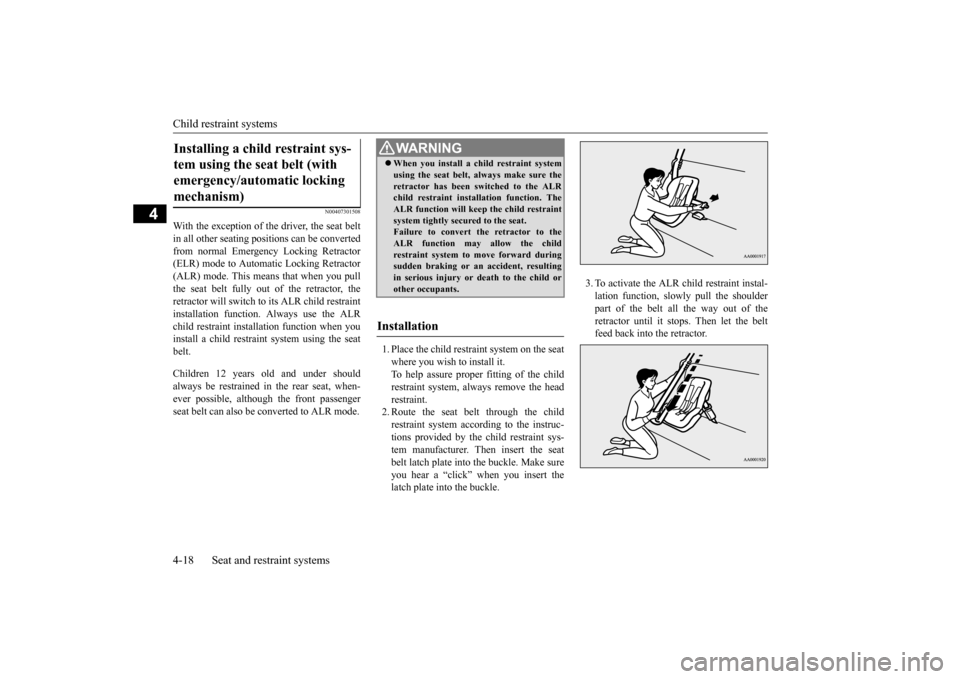
1. Place the child restraint system on the seat where you wish to install it. To help assure proper fitting of the childrestraint system, always remove the head restraint. 2. Route the seat belt through the childrestraint system according to the instruc- tions provided by the child restraint sys- tem manufacturer. Then insert the seatbelt latch plate into the buckle. Make sure you hear a “click” when you insert the latch plate into the buckle.
3. To activate the ALR child restraint instal- lation function, slow
ly pull the shoulder
part of the belt all the way out of theretractor until it stops. Then let the belt feed back into the retractor.
Installing a child restraint sys- tem using the seat belt (with emergency/automatic locking mechanism)
WA R N I N G When you install a child restraint system using the seat belt, always make sure the retractor has been switched to the ALR child restraint installation function. The ALR function will keep the child restraintsystem tightly secured to the seat. Failure to convert the retractor to the ALR function may allow the childrestraint system to move forward during sudden braking or an accident, resulting in serious injury or death to the child orother occupants.
Installation
BK0210800US.bo
ok 18 ページ 2014年4月8日 火曜日 午前11時28分
Page 48 of 338
Supplemental Restraint System (SRS) - airbag
Seat and restraint systems 4-23
4
N00407800519
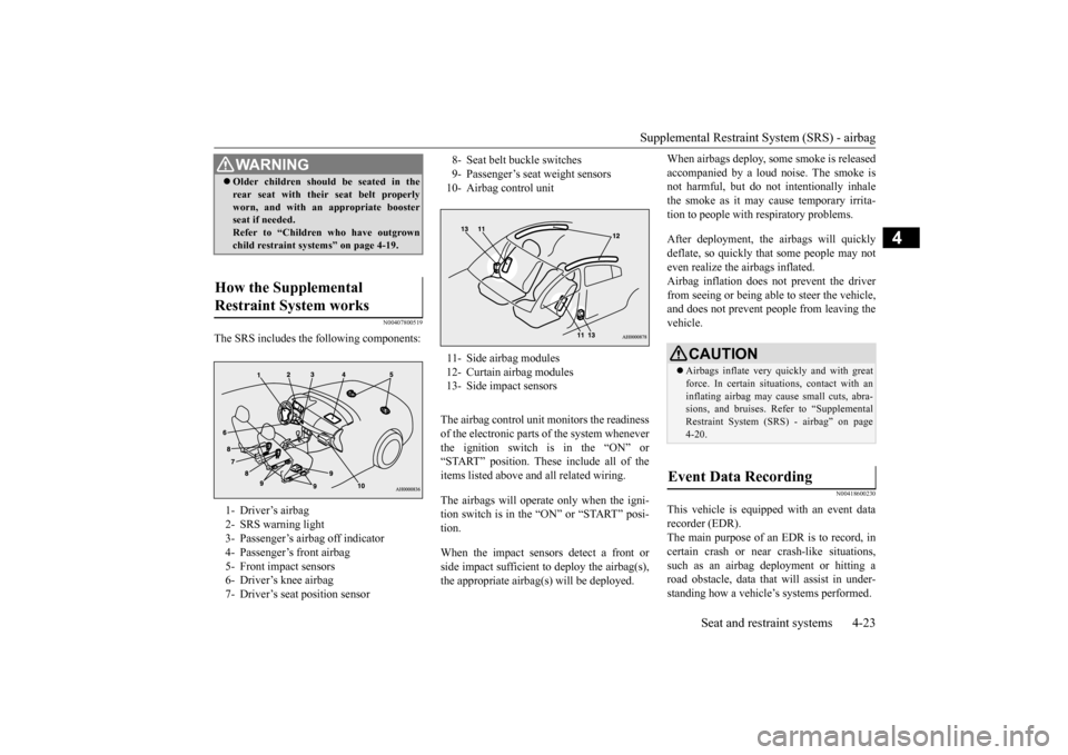
The SRS includes the following components:
The airbag control unit monitors the readiness of the electronic parts of the system whenever the ignition switch is in the “ON” or “START” position. These include all of theitems listed above and all related wiring. The airbags will operate only when the igni- tion switch is in the “ON” or “START” posi- tion. When the impact sensors detect a front or side impact sufficient to deploy the airbag(s), the appropriate airbag(s) will be deployed.
When airbags deploy, some smoke is released accompanied by a loud noise. The smoke is not harmful, but do not intentionally inhale the smoke as it may cause temporary irrita-tion to people with respiratory problems. After deployment, the airbags will quickly deflate, so quickly that some people may not even realize the airbags inflated.Airbag inflation does not prevent the driver from seeing or being able to steer the vehicle, and does not prevent people from leaving thevehicle.
N00418600230
This vehicle is equipped with an event datarecorder (EDR). The main purpose of an EDR is to record, in certain crash or near crash-like situations,such as an airbag deployment or hitting a road obstacle, data that will assist in under- standing how a vehicle’s systems performed.
WA R N I N G Older children should be seated in the rear seat with their seat belt properly worn, and with an appropriate booster seat if needed. Refer to “Children who have outgrownchild restraint systems” on page 4-19.
How the Supplemental Restraint System works 1- Driver’s airbag 2- SRS warning light 3- Passenger’s airbag off indicator 4- Passenger’s front airbag5- Front impact sensors 6- Driver’s knee airbag 7- Driver’s seat position sensor
8- Seat belt buckle switches9- Passenger’s seat weight sensors10- Airbag control unit 11- Side airbag modules 12- Curtain airbag modules 13- Side impact sensors
CAUTION Airbags inflate very quickly and with great force. In certain situations, contact with an inflating airbag may cause small cuts, abra-sions, and bruises. Refer to “Supplemental Restraint System (SRS) - airbag” on page 4-20.
Event Data Recording
BK0210800US.bo
ok 23 ページ 2014年4月8日 火曜日 午前11時28分
Page 50 of 338
Supplemental Restraint System (SRS) - airbagSeat and restraint systems 4-25
4
N00418100251
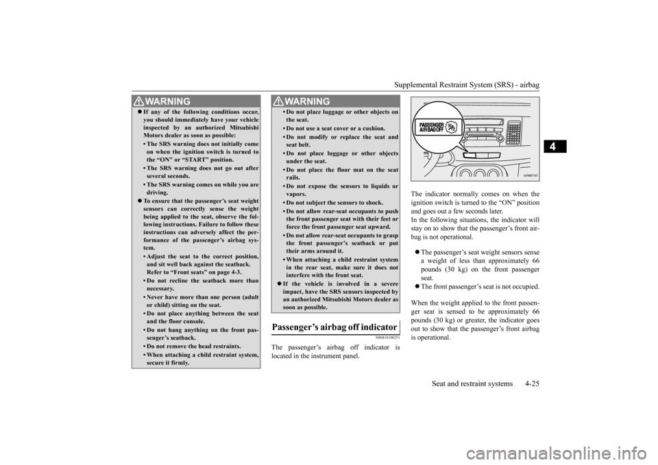
The passenger’s airbag off indicator is
located in the instrument panel. The indicator normally comes on when the
ignition switch is turned to the “ON” position
and goes out a few seconds later.
In the following situations, the indicator will
stay on to show that the passenger’s front air-
bag is not operational.
The passenger’s seat weight sensors sense
a weight of less than approximately 66
pounds (30 kg) on the front passenger
seat.
The front passenger’s seat is not occupied.
When the weight applied to the front passen-
ger seat is sensed to be approximately 66
pounds (30 kg) or greater, the indicator goes
out to show that the passenger’s front airbag
is operational.
WA R N I N G If any of the following conditions occur,
you should immediately have your vehicle
inspected by an authorized Mitsubishi
Motors dealer as soon as possible:• The SRS warning does not initially come
on when the ignition switch is turned to
the “ON” or “START” position.• The SRS warning does not go out afterseveral seconds.• The SRS warning comes on while you aredriving. To ensure that the passenger’s seat weight
sensors can correctly sense the weight
being applied to the seat, observe the fol-
lowing instructions. Failure to follow these
instructions can adversely affect the per-
formance of the passenger’s airbag sys-
tem.• Adjust the seat to the correct position,
and sit well back against the seatback.
Refer to “Front seats” on page 4-3.• Do not recline the seatback more thannecessary.• Never have more than one person (adultor child) sitting on the seat.• Do not place anything between the seatand the floor console.• Do not hang anything on the front pas-senger’s seatback.• Do not remove the head restraints.• When attaching a child restraint system,secure it firmly.
• Do not place luggage or other objects on
the seat.• Do not use a seat cover or a cushion.• Do not modify or replace the seat andseat belt.• Do not place luggage or other objectsunder the seat.• Do not place the floor mat on the seatrails.• Do not expose the sensors to liquids orvapors.• Do not subject the sensors to shock.• Do not allow rear-seat occupants to pushthe front passenger seat with their feet or
force the front passenger seat upward.• Do not allow rear-seat occupants to grasp
the front passenger’s seatback or put
their arms around it.• When attaching a child restraint systemin the rear seat, make sure it does not
interfere with the front seat. If the vehicle is involved in a severe
impact, have the SRS sensors inspected by
an authorized Mitsubishi Motors dealer as
soon as possible.Passenger’s airbag off indicator
WA R N I N G
SC00000500-2.fm 25 ページ 2014年4月18日 金曜日 午後5時49分
Page 51 of 338
Supplemental Restraint System (SRS) - airbag 4-26 Seat and restraint systems
4
N00408301622
Warning light
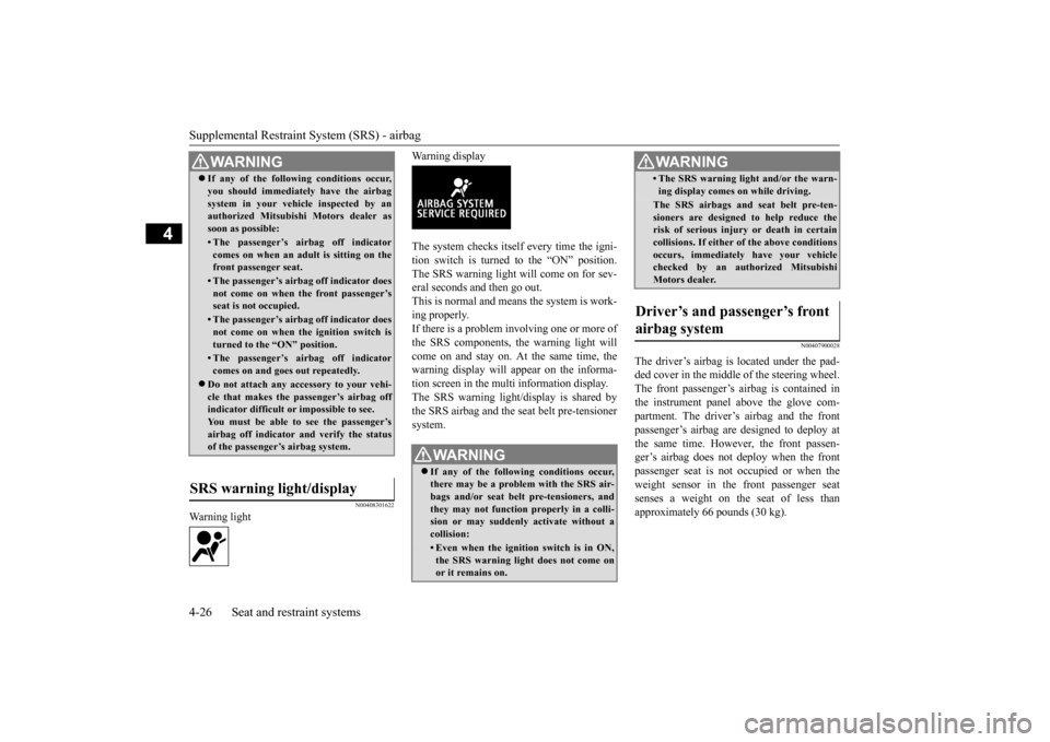
Warning display The system checks itself every time the igni- tion switch is turned to the “ON” position. The SRS warning light will come on for sev-eral seconds and then go out. This is normal and means the system is work- ing properly.If there is a problem involving one or more of the SRS components, the warning light will come on and stay on. At the same time, thewarning display will appear on the informa- tion screen in the multi information display. The SRS warning light/display is shared bythe SRS airbag and the seat belt pre-tensioner system.
N00407900028
The driver’s airbag is located under the pad-ded cover in the middle of the steering wheel. The front passenger’s airbag is contained inthe instrument panel above the glove com- partment. The driver’s airbag and the front passenger’s airbag are designed to deploy atthe same time. However,
the front passen-
ger’s airbag does not deploy when the front passenger seat is not occupied or when theweight sensor in the front passenger seat senses a weight on the seat of less than approximately 66 pounds (30 kg).
WA R N I N G If any of the following conditions occur, you should immediately have the airbag system in your vehicle inspected by an authorized Mitsubishi Motors dealer as soon as possible:• The passenger’s airbag off indicatorcomes on when an adult is sitting on thefront passenger seat.• The passenger’s airbag off indicator doesnot come on when the front passenger’s seat is not occupied.• The passenger’s airbag off indicator doesnot come on when the ignition switch is turned to the “ON” position.• The passenger’s airbag off indicatorcomes on and goes out repeatedly.
Do not attach any accessory to your vehi- cle that makes the passenger’s airbag offindicator difficult or impossible to see. You must be able to see the passenger’s airbag off indicator and verify the statusof the passenger’s airbag system.
SRS warning light/display
WA R N I N G If any of the following conditions occur, there may be a problem with the SRS air- bags and/or seat belt pre-tensioners, and they may not function properly in a colli-sion or may suddenly activate without a collision:• Even when the ignition switch is in ON,the SRS warning light does not come on or it remains on.
• The SRS warning light and/or the warn- ing display comes on while driving.The SRS airbags and seat belt pre-ten- sioners are designed to help reduce therisk of serious injury or death in certain collisions. If either of the above conditions occurs, immediately have your vehiclechecked by an authorized Mitsubishi Motors dealer.
Driver’s and passenger’s front airbag system
WA R N I N G
BK0210800US.bo
ok 26 ページ 2014年4月8日 火曜日 午前11時28分
Page 62 of 338
5
Features and controlsBreak-in period ...............
.................................................................5-3
Keys ..........................................
.......................................................5-3
Electronic immobilizer (Anti-thef
t starting system) ........................5-4
Keyless entry system (if so equipped) ..............................................5-7Free-hand Advanced Security Transmitter (F.A.S.T.-key) (if so equipped) .
.................................................
........................ 5-11
Door locks .......................
...............................................................5-33
Power door locks ............
...............................................................5-35
“Child safety locks” for
rear door ..................................................5-36
Trunk lid ...................................
.....................................................5-37
Inside emergency trunk lid
release ................................................5-38
Theft-alarm system
................................................
........................5-39
Power windows ...............
...............................................................5-42
Sunroof (if so equipped
) .........................................
........................5-44
Parking brake ..................
...............................................................5-46
Steering wheel tilt lock lever .........................................................5-47Inside day/night rearview
mirror ...................................................5-48
Outside rearview mirr
ors ...............................................................5-49
Ignition switch ......
.................................................
........................5-50
Steering wheel lock
................................................
........................5-52
Starting and stopping the e
ngine ....................................................5-52
Turbocharger operation
..........................................
........................5-55
Clutch pedal operation (if so equipped)..........................................5-56Manual transaxle (if so equipped) ..................................................5-56 Twin Clutch SST (Sportronic Shift Transmission) (if so equipped) .
.................................................
........................5-58
All-wheel drive system
..........................................
........................5-70
Cautions on handling of all-wheel drive vehicles ..........................5-70
S-AWC (Super-All Wheel C
ontrol) ............................................... 5-71
Anti-lock braking syst
em .....................................
......................... 5-74
Active stability control
(ASC) ....................
................................... 5-76
Limited-slip differenti
al ..............................
................................... 5-78
Service brake .................
.................................................
............... 5-79
Brake assist system
...............................................
......................... 5-80
Power steering system
..........................................
......................... 5-80
Cruise control ................
.................................................
............... 5-80
Tire pressure monitoring
system ................................................... 5-85
Instrument cluster
.................................................
......................... 5-89
Multi-information disp
lay ....................................
......................... 5-90
Indicator light, warning light, and information screen display list ...........................
.................................................... 5-110
Indicators .................................
.................................................... 5-120
Warning lights ................
.................................................
............. 5-121
Information screen disp
lay ...................................
....................... 5-122
Combination headlights and dimmer switch ............................... 5-124 Turn signal lever ..
.................................................
....................... 5-129
Hazard warning flasher
switch .................................................... 5-130
Front fog light switch
...........................................
....................... 5-130
Wiper and washer swit
ch ......................................
....................... 5-131
Electric rear window def
ogger switch ......................................... 5-135
Horn switch .............................
.................................................... 5-136
Link System .............................
.................................................... 5-136
Bluetooth
® 2.0 interface ..........
.................................................... 5-136
USB input terminal
...............................................
....................... 5-157
Sun visors ......................
.................................................
............. 5-160
12 V power outlet ..........
.................................................
............. 5-160
BK0210800US.bo
ok 1 ページ 2014年4月8日 火曜日 午前11時28分
Page 66 of 338
Electronic immobilizer (Ant
i-theft starting system)
Features and controls 5-5
5
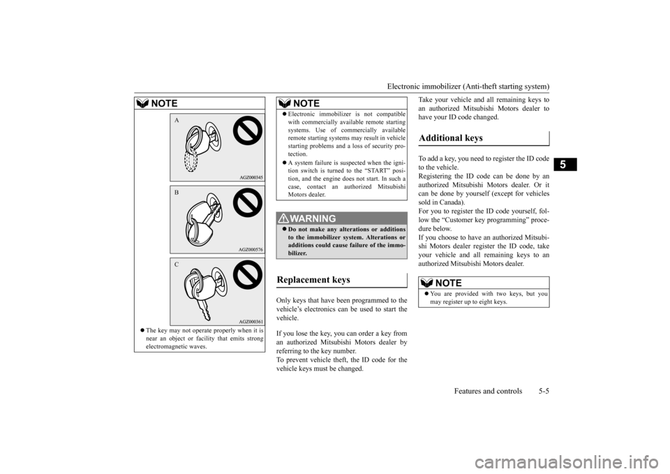
Only keys that have been programmed to the vehicle’s electronics can be used to start thevehicle. If you lose the key, you can order a key from an authorized Mitsubishi Motors dealer by referring to the key number.To prevent vehicle theft, the ID code for the vehicle keys must be changed.
Take your vehicle and all remaining keys to an authorized Mitsubishi Motors dealer to have your ID code changed. To add a key, you need to register the ID code to the vehicle. Registering the ID code can be done by anauthorized Mitsubishi Motors dealer. Or itcan be done by yourself (except for vehicles sold in Canada). For you to register the ID code yourself, fol-low the “Customer key programming” proce- dure below. If you choose to have an authorized Mitsubi-shi Motors dealer register the ID code, take your vehicle and all remaining keys to an authorized Mitsubishi Motors dealer.
The key may not operate properly when it is near an object or facility that emits strongelectromagnetic waves.NOTE
ABC
Electronic immobilizer is not compatible with commercially available remote starting systems. Use of commercially available remote starting systems may result in vehicle starting problems and a lo
ss of security pro-
tection. A system failure is suspected when the igni- tion switch is turned to the “START” posi- tion, and the engine does not start. In such a case, contact an authorized MitsubishiMotors dealer.WA R N I N G Do not make any alterations or additions to the immobilizer system. Alterations or additions could cause failure of the immo-bilizer.
Replacement keys
NOTE
Additional keys
NOTE
You are provided with two keys, but you may register up to eight keys.
BK0210800US.bo
ok 5 ページ 2014年4月8日 火曜日 午前11時28分
Page 67 of 338
Electronic immobilizer (Anti-theft starting system) 5-6 Features and controls
5
N00562200070
You can program new keys to the system if you have two valid (already registered) keys and blank (not registered) immobilizer key(specially cut for your vehicle at your Mit- subishi Motors dealer) by doing the follow- ing: 1. Insert the first valid key into the ignition switch and turn the key to the “ON” posi-tion for 5 seconds. 2. Turn the key to the “LOCK” position and remove the first key.3. Within 30 seconds of turning the first key to the “LOCK” position, insert the second valid key into the ignition and turn it tothe “ON” position. About 10 seconds later, the immobilizer display will start to blink.
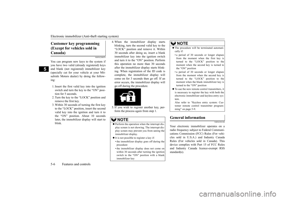
4. When the immobilizer display starts blinking, turn the second valid key to the “LOCK” position and remove it. Within 30 seconds after doing so, insert a blankimmobilizer key into the ignition switch and turn it to the “ON” position. Perform this operation no more than 30 secondsafter the immobilizer display starts blink- ing. When registration of the ID code is complete, the immobilizer display willcome on for 3 seconds then go off. If anerror occurs, the immobilizer display will go off during the procedure. 5. If you wish to register another key, per- form the process again from step 1.
N00562301108
Your electronic immobilizer operates on a radio frequency subject to Federal Communi- cations Commission (FCC) Rules (For vehi- cles sold in U.S.A.) and Industry CanadaRules (For vehicles sold in Canada). This device complies with Part 15 of FCC Rules and Industry Canada licence-exempt RSSstandard(s).
Customer key programming (Except for vehicles sold in Canada)
NOTE
Perform the operation when the interrupt dis- play screen is not showing. The interrupt dis- play screen may prevent you from seeing the immobilizer display. It is not possible to register a key if: • the immobilizer display goes off during the procedure • the immobilizer display does not come on within 30 seconds after turning the ignition switch to the “ON” position with a blankimmobilizer key
The procedure will be terminated automati- cally if: • a period of 30 seconds or longer elapses from the moment when the first key isturned to the “LOCK” position to the moment when the second key is turned to the “ON” position • a period of 30 seconds or longer elapses from the moment when the second key isturned to the “LOCK” position to the moment when the blank immobilizer key is turned to the “ON” position
To use the new remote control transmitters, it is necessary to register the key with both theelectronic immobilizer and keyless entry sys- tem. Also refer to “Keyless entry system: Cus-tomer remote control transmitter program- ming” on page 5-9.
General information
NOTE
BK0210800US.bo
ok 6 ページ 2014年4月8日 火曜日 午前11時28分
Page 69 of 338
Keyless entry system (if so equipped) 5-8 Features and controls
5
N00543501097
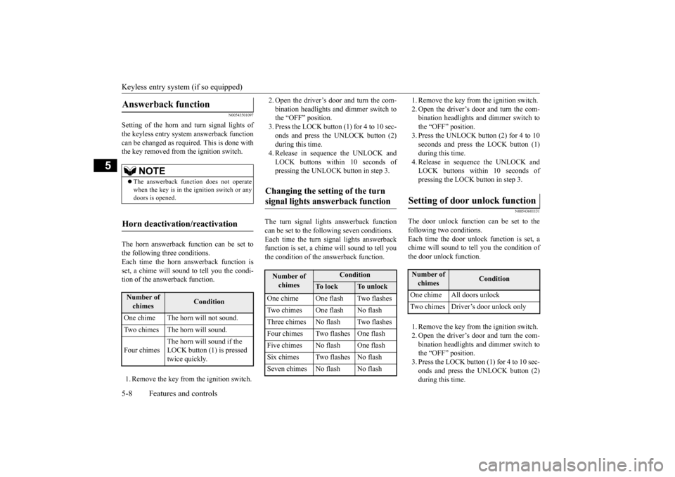
Setting of the horn and turn signal lights of the keyless entry system answerback functioncan be changed as required. This is done with the key removed from the ignition switch. The horn answerback function can be set to the following three conditions. Each time the horn answerback function isset, a chime will sound to tell you the condi- tion of the answerback function. 1. Remove the key from the ignition switch.
2. Open the driver’s door and turn the com- bination headlights and dimmer switch to the “OFF” position. 3. Press the LOCK button (1) for 4 to 10 sec-onds and press the UNLOCK button (2) during this time. 4. Release in sequence the UNLOCK andLOCK buttons within 10 seconds of pressing the UNLOCK button in step 3.
The turn signal lights answerback function can be set to the following seven conditions.Each time the turn signal lights answerback function is set, a chime will sound to tell you the condition of the answerback function.
1. Remove the key from the ignition switch. 2. Open the driver’s door and turn the com- bination headlights and dimmer switch to the “OFF” position.3. Press the UNLOCK button (2) for 4 to 10 seconds and press the LOCK button (1) during this time.4. Release in sequence the UNLOCK and LOCK buttons within 10 seconds of pressing the LOCK button in step 3.
N00543601131
The door unlock function can be set to the following two conditions. Each time the door unlock function is set, achime will sound to te
ll you the condition of
the door unlock function. 1. Remove the key from the ignition switch. 2. Open the driver’s door and turn the com-bination headlights and dimmer switch to the “OFF” position. 3. Press the LOCK button (1) for 4 to 10 sec-onds and press the UNLOCK button (2) during this time.
Answerback function
NOTE
The answerback function does not operate when the key is in the ignition switch or any doors is opened.
Horn deactivation/reactivation
Number of chimes
Condition
One chime The horn will not sound. Two chimes The horn will sound. Four chimes
The horn will sound if the LOCK button (1) is pressed twice quickly.
Changing the setting of the turn signal lights answerback function
Number of chimes
Condition
To l o c k
To u n l o c k
One chime One flash Two flashesTwo chimes One flash No flashThree chimes No flash Two flashesFour chimes Two flashes One flashFive chimes No flash One flashSix chimes Two flashes No flashSeven chimes No flash No flash
Setting of door unlock function
Number of chimes
Condition
One chime All doors unlock Two chimes Driver’s door unlock only
BK0210800US.bo
ok 8 ページ 2014年4月8日 火曜日 午前11時28分
Page 71 of 338
Keyless entry system (if so equipped) 5-10 Features and controls
5
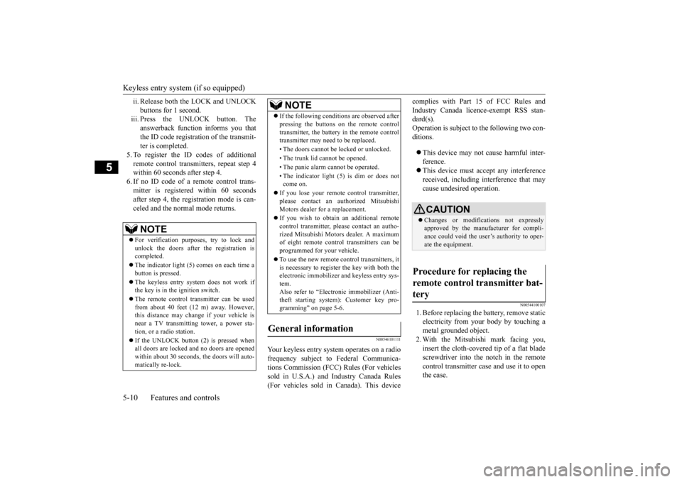
ii. Release both the LOCK and UNLOCK buttons for 1 second.
iii. Press the UNLOCK button. The
answerback function informs you thatthe ID code registra
tion of the transmit-
ter is completed.
5. To register the ID codes of additionalremote control transmitters, repeat step 4 within 60 seconds after step 4. 6. If no ID code of a remote control trans-mitter is registered within 60 secondsafter step 4, the registration mode is can- celed and the normal mode returns.
N0054610
1111
Your keyless entry system operates on a radio frequency subject to Federal Communica- tions Commission (FCC) Rules (For vehicles sold in U.S.A.) and Industry Canada Rules(For vehicles sold in Canada). This device
complies with Part 15 of FCC Rules and Industry Canada licence-exempt RSS stan- dard(s). Operation is subject to the following two con-ditions. This device may not cause harmful inter- ference. This device must accept any interference received, including interference that may cause undesired operation.
N00544100107
1. Before replacing the battery, remove static electricity from your body by touching ametal grounded object. 2. With the Mitsubishi mark facing you, insert the cloth-covered tip of a flat bladescrewdriver into the notch in the remote control transmitter case and use it to open the case.
NOTE
For verification purposes, try to lock and unlock the doors after the registration iscompleted. The indicator light (5) comes on each time a button is pressed. The keyless entry system does not work if the key is in the ignition switch. The remote control transmitter can be used from about 40 feet (12 m) away. However, this distance may change if your vehicle is near a TV transmitting tower, a power sta- tion, or a radio station. If the UNLOCK button (2) is pressed when all doors are locked and no doors are opened within about 30 seconds, the doors will auto-matically re-lock.
If the following conditions are observed after pressing the buttons on the remote control transmitter, the battery in the remote control transmitter may need to be replaced. • The doors cannot be locked or unlocked. • The trunk lid cannot be opened.• The panic alarm cannot be operated. • The indicator light (5) is dim or does not come on.
If you lose your remote control transmitter, please contact an authorized Mitsubishi Motors dealer for a replacement. If you wish to obtain an additional remote control transmitter, please contact an autho-rized Mitsubishi Motors dealer. A maximum of eight remote control transmitters can be programmed for your vehicle. To use the new remote control transmitters, it is necessary to register the key with both theelectronic immobilizer and keyless entry sys- tem. Also refer to “Electr
onic immobilizer (Anti-
theft starting system): Customer key pro- gramming” on page 5-6.
General information
NOTE
CAUTION Changes or modifications not expressly approved by the manufacturer for compli- ance could void the user’s authority to oper- ate the equipment.
Procedure for replacing the remote control transmitter bat- tery
BK0210800US.bo
ok 10 ページ 2014年4月8日 火曜日 午前11時28分