MITSUBISHI LANCER EVOLUTION IX 2005 Owner's Guide
LANCER EVOLUTION IX 2005
MITSUBISHI
MITSUBISHI
https://www.carmanualsonline.info/img/19/57323/w960_57323-0.png
MITSUBISHI LANCER EVOLUTION IX 2005 Owner's Guide
Page 161 of 364
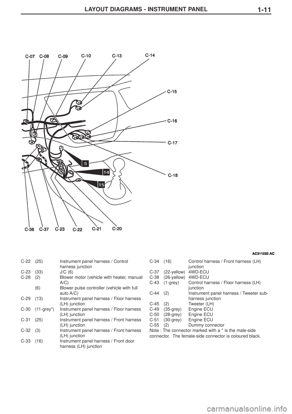
LAYOUT DIAGRAMS - INSTRUMENT PANEL1-11
C-22 (25) Instrument panel harness / Control
harness junction
C-23 (33) J/C (6)
C-28 (2) Blower motor (vehicle with heater, manual
A/C)
(6) Blower pulse controller (vehicle with full
auto A/C)
C-29 (13) Instrument panel harness / Floor harness
(LH) junction
C-30 (11-grey*) Instrument panel harness / Floor harness
(LH) junction
C-31 (25) Instrument panel harness / Front harness
(LH) junction
C-32 (3) Instrument panel harness / Front harness
(LH) junction
C-33 (16) Instrument panel harness / Front door
harness (LH) junctionC-34 (16) Control harness / Front harness (LH)
junction
C-37 (22-yellow) 4WD-ECU
C-38 (26-yellow) 4WD-ECU
C-43 (1-grey) Control harness / Floor harness (LH)
junction
C-44 (2) Instrument panel harness / Tweeter sub-
harness junction
C-45 (2) Tweeter (LH)
C-49 (35-grey) Engine ECU
C-50 (28-grey) Engine ECU
C-51 (30-grey) Engine ECU
C-55 (2) Dummy connector
Note : The connector marked with a * is the male-side
connector. The female-side connector is coloured black.
Page 163 of 364
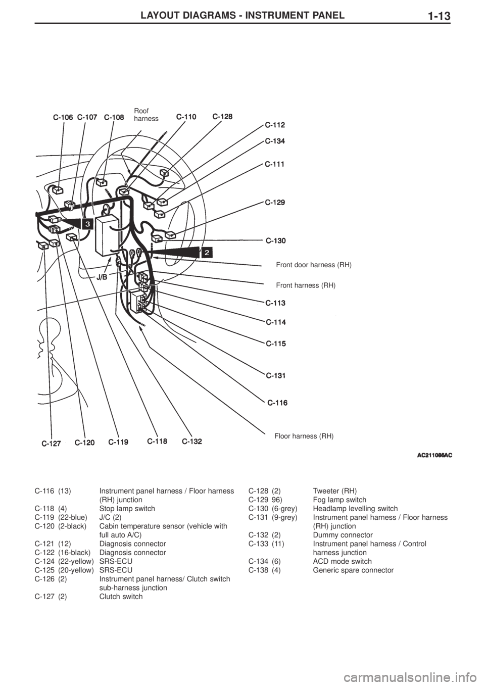
LAYOUT DIAGRAMS - INSTRUMENT PANEL1-13
C-116 (13) Instrument panel harness / Floor harness
(RH) junction
C-118 (4) Stop lamp switch
C-119 (22-blue) J/C (2)
C-120 (2-black) Cabin temperature sensor (vehicle with
full auto A/C)
C-121 (12) Diagnosis connector
C-122 (16-black) Diagnosis connector
C-124 (22-yellow) SRS-ECU
C-125 (20-yellow) SRS-ECU
C-126 (2) Instrument panel harness/ Clutch switch
sub-harness junction
C-127 (2) Clutch switchC-128 (2) Tweeter (RH)
C-129 96) Fog lamp switch
C-130 (6-grey) Headlamp levelling switch
C-131 (9-grey) Instrument panel harness / Floor harness
(RH) junction
C-132 (2) Dummy connector
C-133 (11) Instrument panel harness / Control
harness junction
C-134 (6) ACD mode switch
C-138 (4) Generic spare connector
Roof
harness
Front harness (RH) Front door harness (RH)
Floor harness (RH)
Page 165 of 364
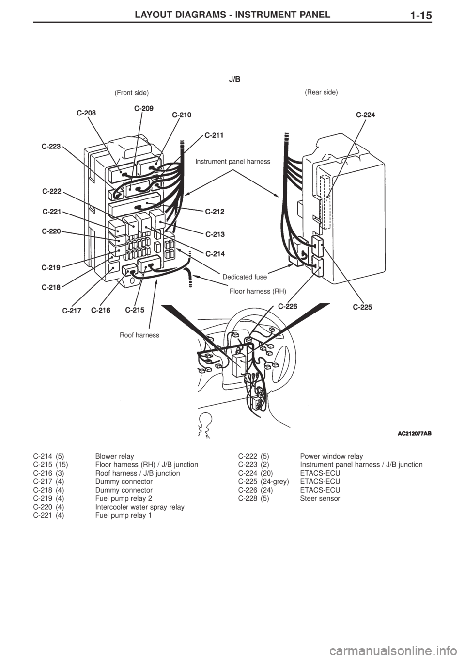
LAYOUT DIAGRAMS - INSTRUMENT PANEL1-15
C-214 (5) Blower relay
C-215 (15) Floor harness (RH) / J/B junction
C-216 (3) Roof harness / J/B junction
C-217 (4) Dummy connector
C-218 (4) Dummy connector
C-219 (4) Fuel pump relay 2
C-220 (4) Intercooler water spray relay
C-221 (4) Fuel pump relay 1C-222 (5) Power window relay
C-223 (2) Instrument panel harness / J/B junction
C-224 (20) ETACS-ECU
C-225 (24-grey) ETACS-ECU
C-226 (24) ETACS-ECU
C-228 (5) Steer sensor
(Front side)
Instrument panel harness
Dedicated fuse
Floor harness (RH)
Roof harness(Rear side)
Page 171 of 364
2-1
SECTION 2
INDIVIDUAL PART
INSTALLATION POSITIONS
CONTENTS
Sensors ...................................................2-2
ECU ..........................................................2-6
Relays ......................................................2-9
Solenoid valves.....................................2-10Fusible links / Fuses ............................2-12
Inspection connectors /
Spare connectors .................................2-13
Ground cables.......................................2-14
Earths.....................................................2-15
Page 174 of 364
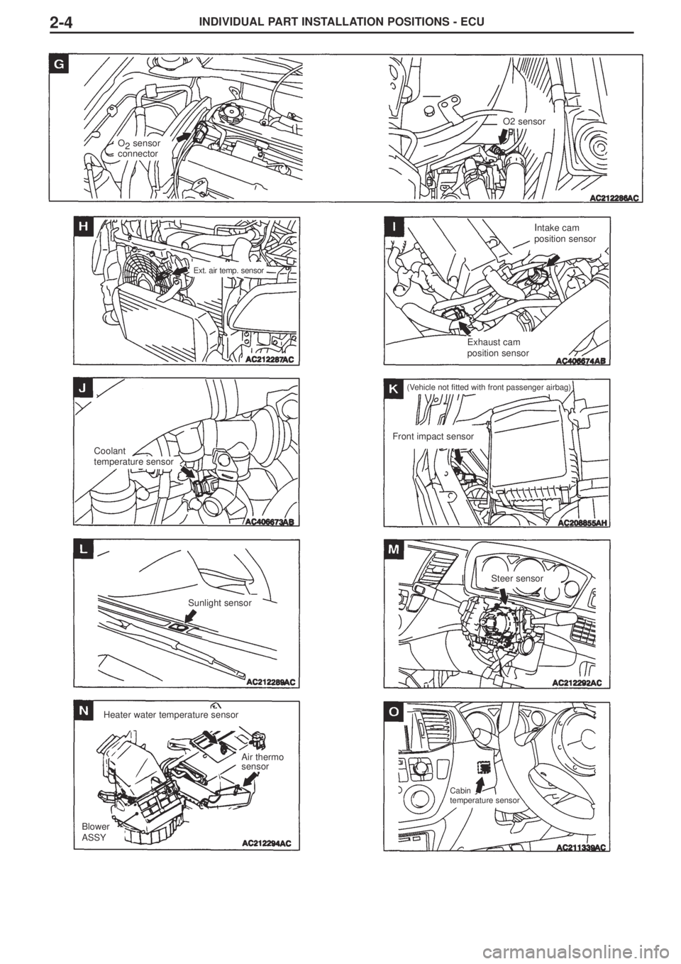
INDIVIDUAL PART INSTALLATION POSITIONS - ECU2-4
O
2sensor
connector
Ext. air temp. sensor
Coolant
temperature sensor
Intake cam
position sensor
Exhaust cam
position sensor
(Vehicle not fitted with front passenger airbag)
O2 sensor
Front impact sensor
Steer sensor
Sunlight sensor
Heater water temperature sensor
Air thermo
sensor
Blower
ASSY
Cabin
temperature sensor
Page 176 of 364
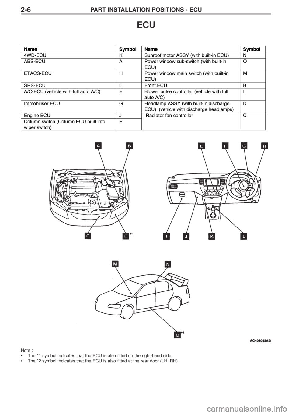
PART INSTALLATION POSITIONS - ECU2-6
ECU
Note :
•The *1 symbol indicates that the ECU is also fitted on the right-hand side.
•The *2 symbol indicates that the ECU is also fitted at the rear door (LH, RH).
Page 177 of 364
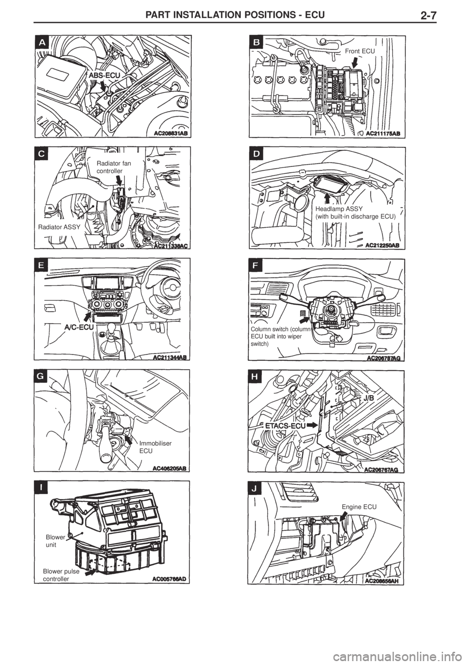
PART INSTALLATION POSITIONS - ECU2-7
Front ECU
Headlamp ASSY
(with built-in discharge ECU) Radiator fan
controller
Radiator ASSY
Column switch (column
ECU built into wiper
switch)
Immobiliser
ECU
Blower
unit
Blower pulse
controllerEngine ECU
Page 178 of 364
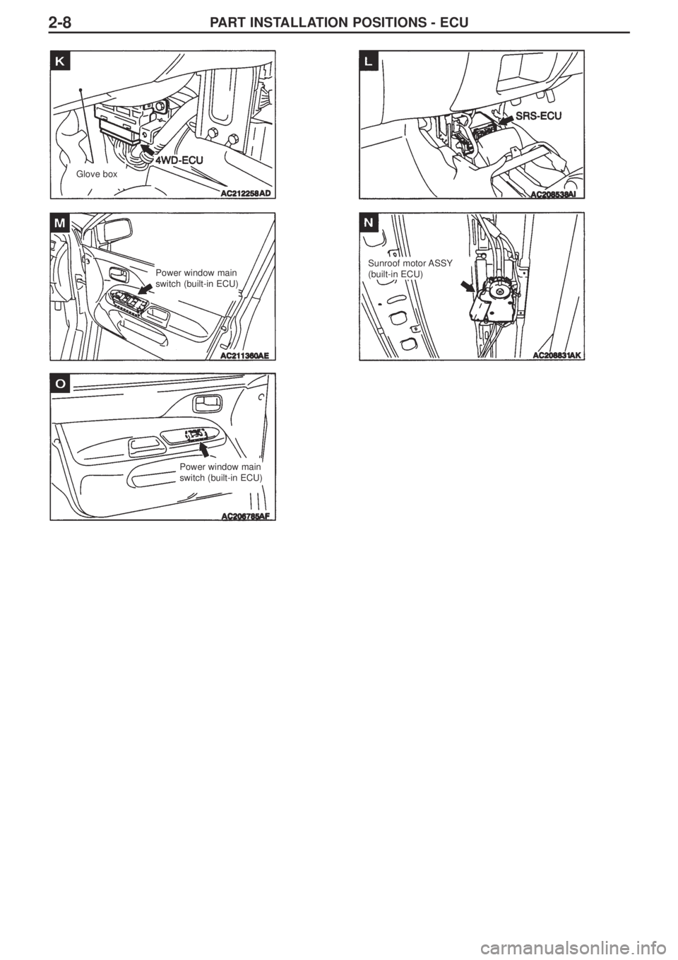
PART INSTALLATION POSITIONS - ECU2-8
Glove box
Power window main
switch (built-in ECU)Sunroof motor ASSY
(built-in ECU)
Power window main
switch (built-in ECU)
Page 183 of 364
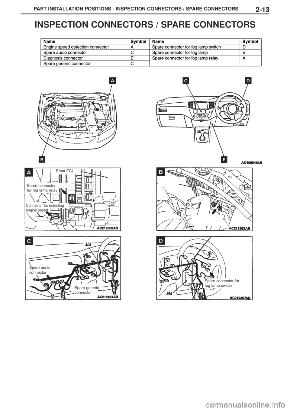
PART INSTALLATION POSITIONS - INSPECTION CONNECTORS / SPARE CONNECTORS2-13
INSPECTION CONNECTORS / SPARE CONNECTORS
Front ECU
Spare connector
for fog lamp relay
Spare audio
connector
Spare generic
connectorSpare connector for
fog lamp switch
Connector for detecting
engine speed
Page 186 of 364
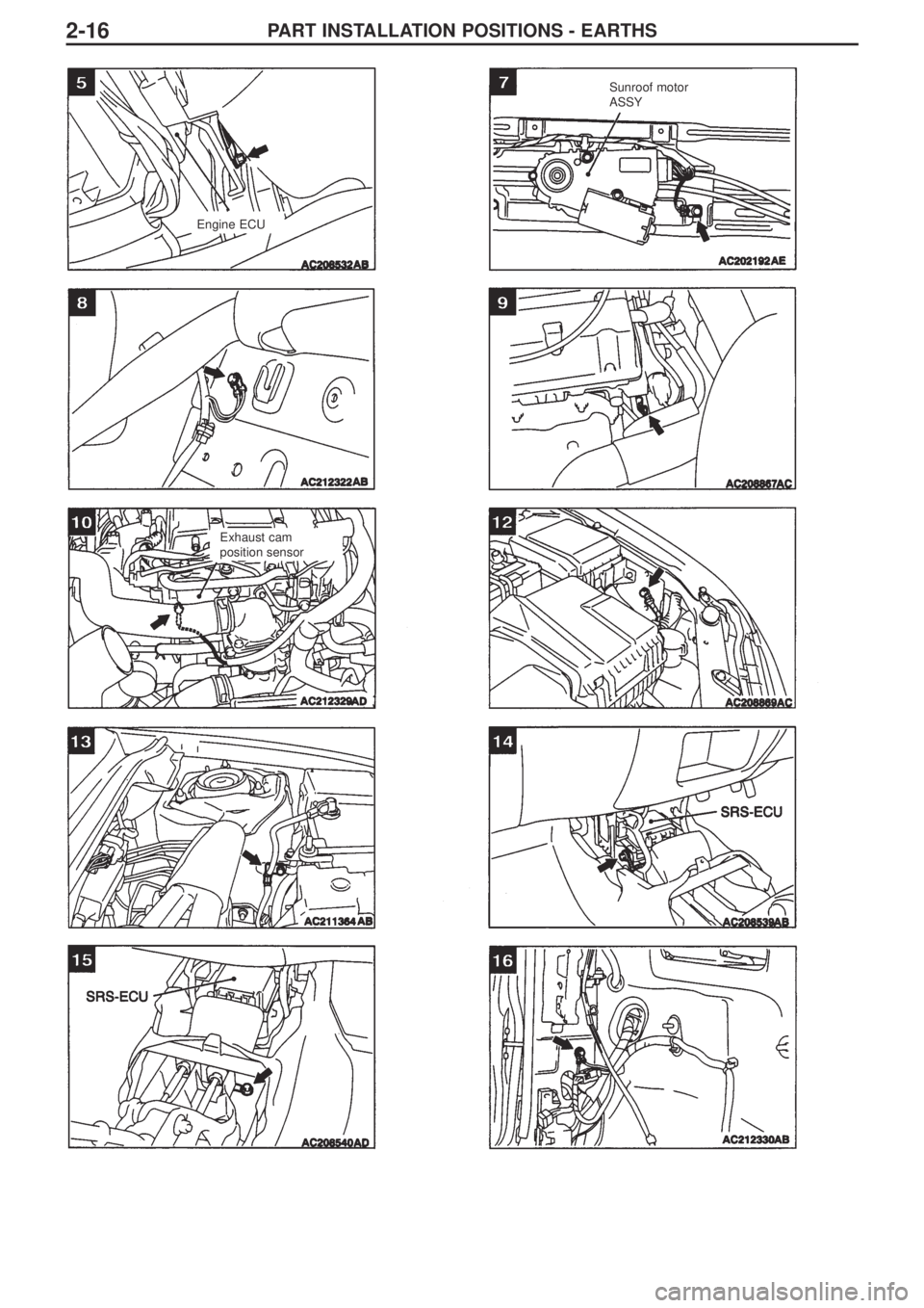
PART INSTALLATION POSITIONS - EARTHS2-16
Engine ECU
Exhaust cam
position sensorSunroof motor
ASSY

