display MITSUBISHI LANCER EVOLUTION IX 2005 Workshop Manual
[x] Cancel search | Manufacturer: MITSUBISHI, Model Year: 2005, Model line: LANCER EVOLUTION IX, Model: MITSUBISHI LANCER EVOLUTION IX 2005Pages: 364, PDF Size: 14.38 MB
Page 30 of 364

ENGINE – TIMING BELT, TIMING BELT B11-24
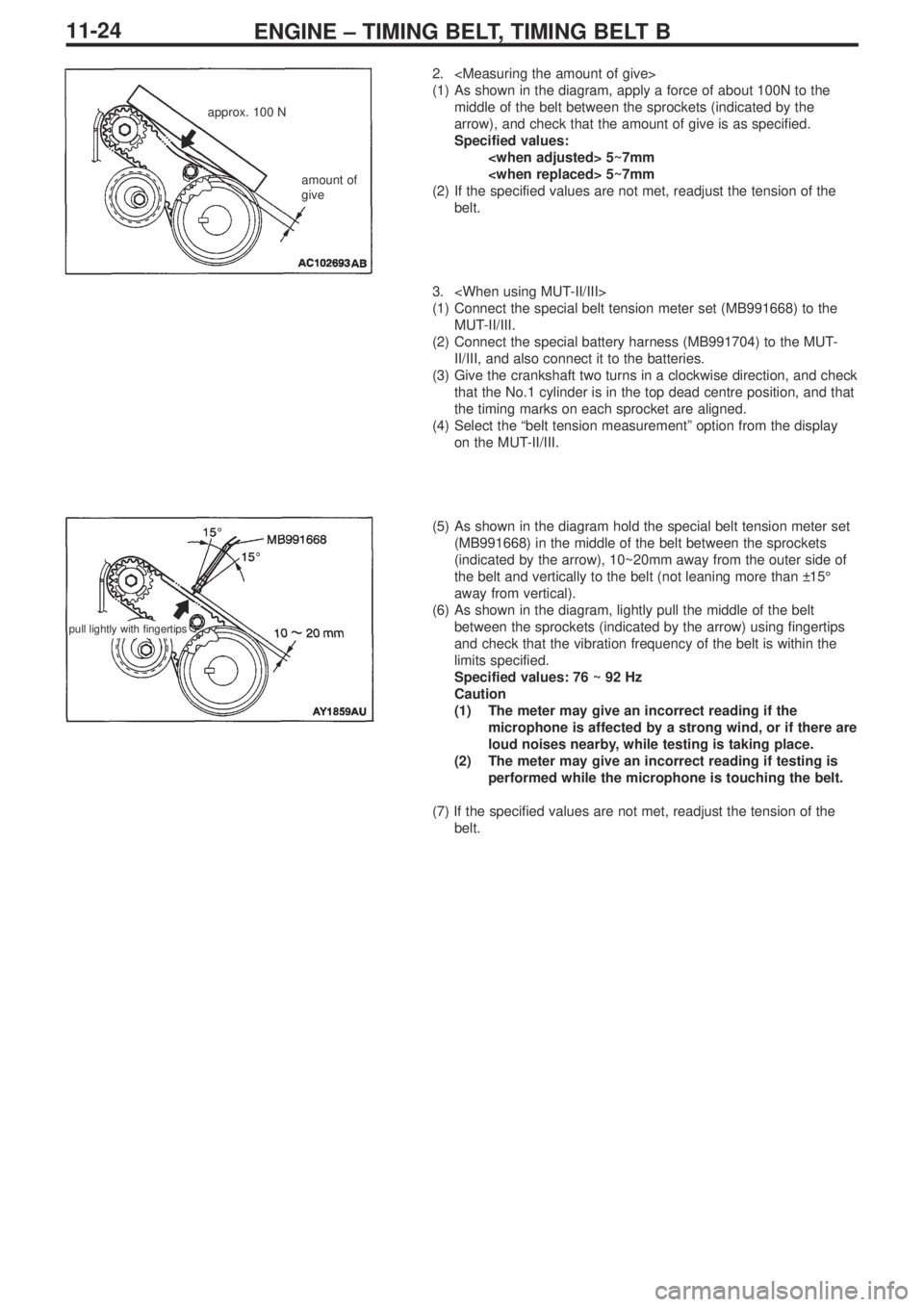
2.
(1) As shown in the diagram, apply a force of about 100N to the
middle of the belt between the sprockets (indicated by the
arrow), and check that the amount of give is as specified.
Specified values:
(2) If the specified values are not met, readjust the tension of the
belt.
3.
(1) Connect the special belt tension meter set (MB991668) to the
MUT-II/III.
(2) Connect the special battery harness (MB991704) to the MUT-
II/III, and also connect it to the batteries.
(3) Give the crankshaft two turns in a clockwise direction, and check
that the No.1 cylinder is in the top dead centre position, and that
the timing marks on each sprocket are aligned.
(4) Select the “belt tension measurement” option from the display
on the MUT-II/III.
(5) As shown in the diagram hold the special belt tension meter set
(MB991668) in the middle of the belt between the sprockets
(indicated by the arrow), 10~20mm away from the outer side of
the belt and vertically to the belt (not leaning more than ±15°
away from vertical).
(6) As shown in the diagram, lightly pull the middle of the belt
between the sprockets (indicated by the arrow) using fingertips
and check that the vibration frequency of the belt is within the
limits specified.
Specified values: 76 ~ 92 Hz
Caution
(1) The meter may give an incorrect reading if the
microphone is affected by a strong wind, or if there are
loud noises nearby, while testing is taking place.
(2) The meter may give an incorrect reading if testing is
performed while the microphone is touching the belt.
(7) If the specified values are not met, readjust the tension of the
belt.
approx. 100 N
amount of
give
pull lightly with fingertips
Page 56 of 364

13A-16MPI – TROUBLESHOOTING
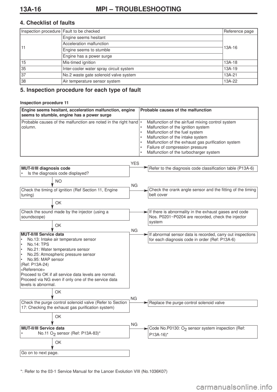
Check the purge control solenoid valve (Refer to Section
17: Checking the exhaust gas purification system)
MUT-II/III Service data
•No.11 O
2sensor (Ref: P13A-83)*
Refer to the diagnosis code classification table (P13A-6)MUT-II/III diagnosis code
•Is the diagnosis code displayed?
Check the timing of ignition (Ref Section 11, Engine
tuning)
Check the sound made by the injector (using a
soundscope)
Check the crank angle sensor and the fitting of the timing
belt cover
If there is abnormality in the exhaust gases and code
Nos. P0201~P0204 are recorded, check the injector
system
If abnormal sensor data is recorded, carry out inspections
for each diagnosis code in order (Ref: P13A-6)
Replace the purge control solenoid valve
Code No.P0130: O
2sensor system inspection (Ref:
P13A-16)*
Go on to next page.
MUT-II/III Service data
•No.13: Intake air temperature sensor
•No.14: TPS
•No.21: Water temperature sensor
•No.25: Atmospheric pressure sensor
•No.95: MAP sensor
(Ref: P13A-24)
Proceed to OK if all service data levels are normal.
Proceed via NG even if only one of the service data
levels is abnormal.
*: Refer to the 03-1 Service Manual for the Lancer Evolution VIII (No.1036K07)
NO
OK
OK
OK
OK
OK
YES
NG
NG
NG
NG
Inspection procedureFault to be checkedReference page
11
Engine seems hesitant
13A-16Acceleration malfunction
Engine seems to stumble
Engine has a power surge
15Mis-timed ignition13A-18
35Inter-cooler water spray circuit system13A-19
37No.2 waste gate solenoid valve system13A-21
38Air temperature sensor system13A-22
Engine seems hesitant, acceleration malfunction, engine
seems to stumble, engine has a power surgeProbable causes of the malfunction
Probable causes of the malfunction are noted in the right hand
column.•Malfunction of the air/fuel mixing control system
•Malfunction of the ignition system
•Malfunction of the fuel system
•Malfunction of the intake system
•Malfunction of the exhaust gas purification system
•Failure of compression pressure
•Malfunction of the turbocharger system
5. Inspection procedure for each type of fault
Inspection procedure 11
4. Checklist of faults
Page 58 of 364

13A-18MPI – TROUBLESHOOTING
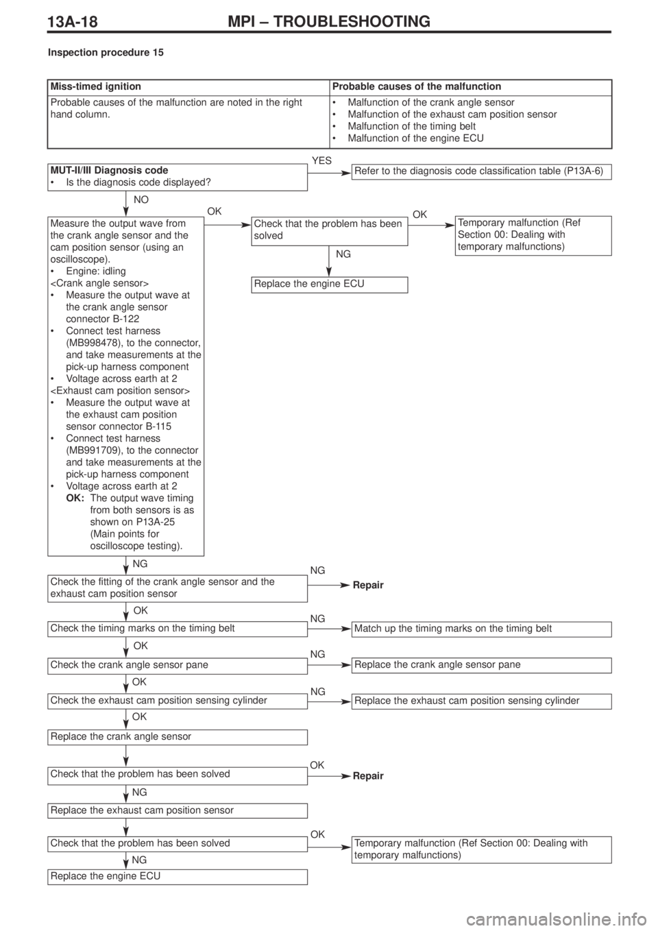
Measure the output wave from
the crank angle sensor and the
cam position sensor (using an
oscilloscope).
•Engine: idling
•Measure the output wave at
the crank angle sensor
connector B-122
•Connect test harness
(MB998478), to the connector,
and take measurements at the
pick-up harness component
•Voltage across earth at 2
•Measure the output wave at
the exhaust cam position
sensor connector B-115
•Connect test harness
(MB991709), to the connector
and take measurements at the
pick-up harness component
•Voltage across earth at 2
OK:The output wave timing
from both sensors is as
shown on P13A-25
(Main points for
oscilloscope testing).Check that the problem has been
solvedTemporary malfunction (Ref
Section 00: Dealing with
temporary malfunctions)
Replace the engine ECU
NO
OK
NG
OK
NG
NG
NG
Repair
Miss-timed ignitionProbable causes of the malfunction
Probable causes of the malfunction are noted in the right
hand column.•Malfunction of the crank angle sensor
•Malfunction of the exhaust cam position sensor
•Malfunction of the timing belt
•Malfunction of the engine ECU
Inspection procedure 15
Refer to the diagnosis code classification table (P13A-6)MUT-II/III Diagnosis code
•Is the diagnosis code displayed?YES
Repair
Replace the crank angle sensor pane
Match up the timing marks on the timing belt
Replace the exhaust cam position sensing cylinder
Temporary malfunction (Ref Section 00: Dealing with
temporary malfunctions)
Check the exhaust cam position sensing cylinder
Check the fitting of the crank angle sensor and the
exhaust cam position sensor
Check the timing marks on the timing belt
Check the crank angle sensor pane
Replace the crank angle sensor
Check that the problem has been solved
Replace the exhaust cam position sensor
Check that the problem has been solved
Replace the engine ECU
OK
OK
OK
NG
OK
NG
NG
NG
OK
OK