door lock MITSUBISHI LANCER EVOLUTION IX 2005 Workshop Manual
[x] Cancel search | Manufacturer: MITSUBISHI, Model Year: 2005, Model line: LANCER EVOLUTION IX, Model: MITSUBISHI LANCER EVOLUTION IX 2005Pages: 364, PDF Size: 14.38 MB
Page 141 of 364
GENERAL INFORMATION - HOW TO READ THE WIRING DIAGRAMS0-3
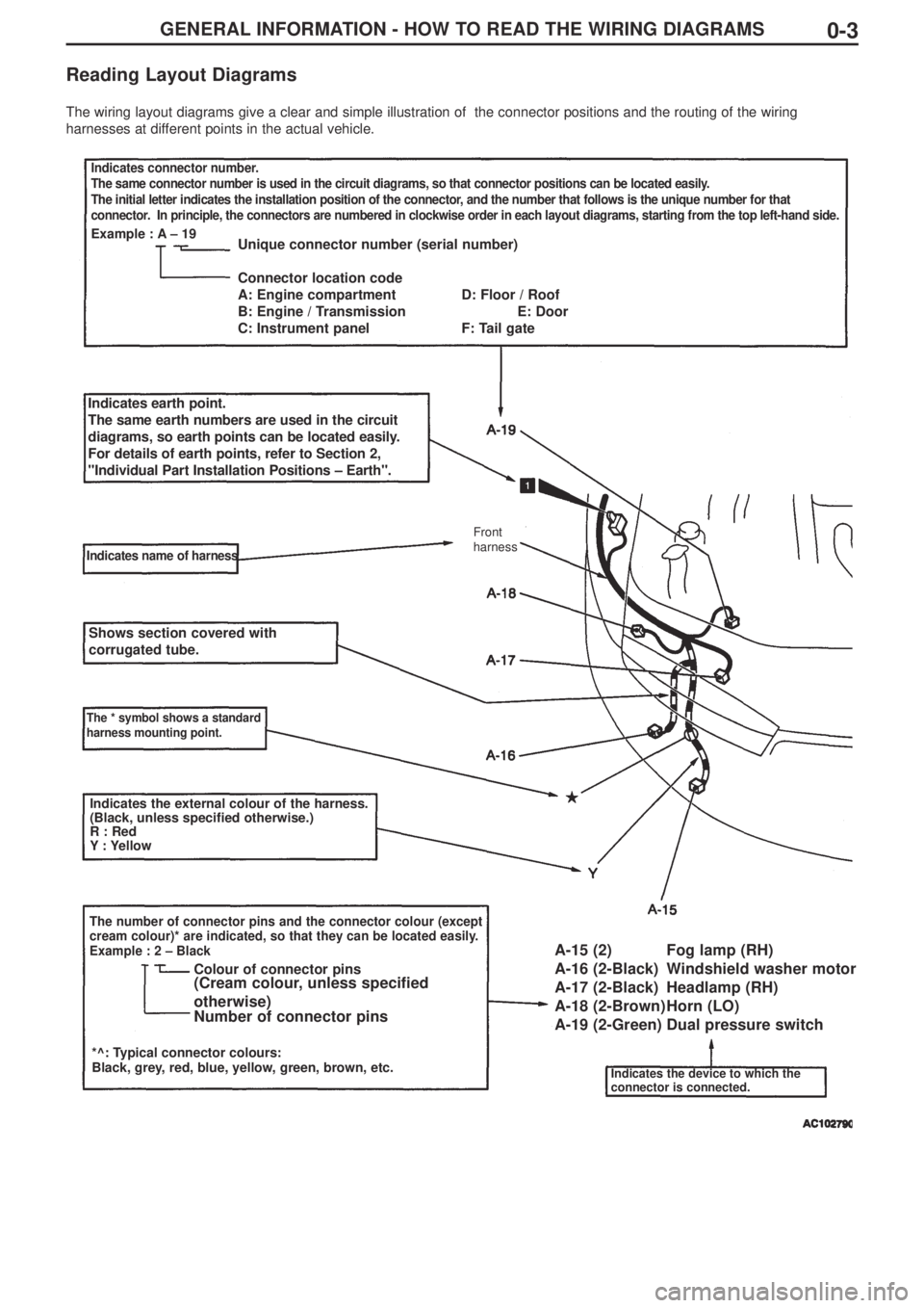
Reading Layout Diagrams
The wiring layout diagrams give a clear and simple illustration of the connector positions and the routing of the wiring
harnesses at different points in the actual vehicle.
Indicates connector number.
The same connector number is used in the circuit diagrams, so that connector positions can be located easily.
The initial letter indicates the installation position of the connector, and the number that follows is the unique number for that
connector. In principle, the connectors are numbered in clockwise order in each layout diagrams, starting from the top left-hand side.
Example : A – 19Unique connector number (serial number)
Connector location code
A: Engine compartment D: Floor / Roof
B: Engine / Transmission E: Door
C: Instrument panel F: Tail gate
Indicates earth point.
The same earth numbers are used in the circuit
diagrams, so earth points can be located easily.
For details of earth points, refer to Section 2,
"Individual Part Installation Positions – Earth".
Indicates name of harness
Shows section covered with
corrugated tube.
The * symbol shows a standard
harness mounting point.
Indicates the external colour of the harness.
(Black, unless specified otherwise.)
R : Red
Y: Yellow
The number of connector pins and the connector colour (except
cream colour)* are indicated, so that they can be located easily.
Example : 2 – Black
*^: Typical connector colours:
Black, grey, red, blue, yellow, green, brown, etc.
Colour of connector pins(Cream colour, unless specified
otherwise)
Number of connector pinsA-15 (2) Fog lamp (RH)
A-16 (2-Black) Windshield washer motor
A-17 (2-Black) Headlamp (RH)
A-18 (2-Brown) Horn (LO)
A-19 (2-Green) Dual pressure switch
Indicates the device to which the
connector is connected.
Front
harness
Page 160 of 364
LAYOUT DIAGRAMS - INSTRUMENT PANEL1-10
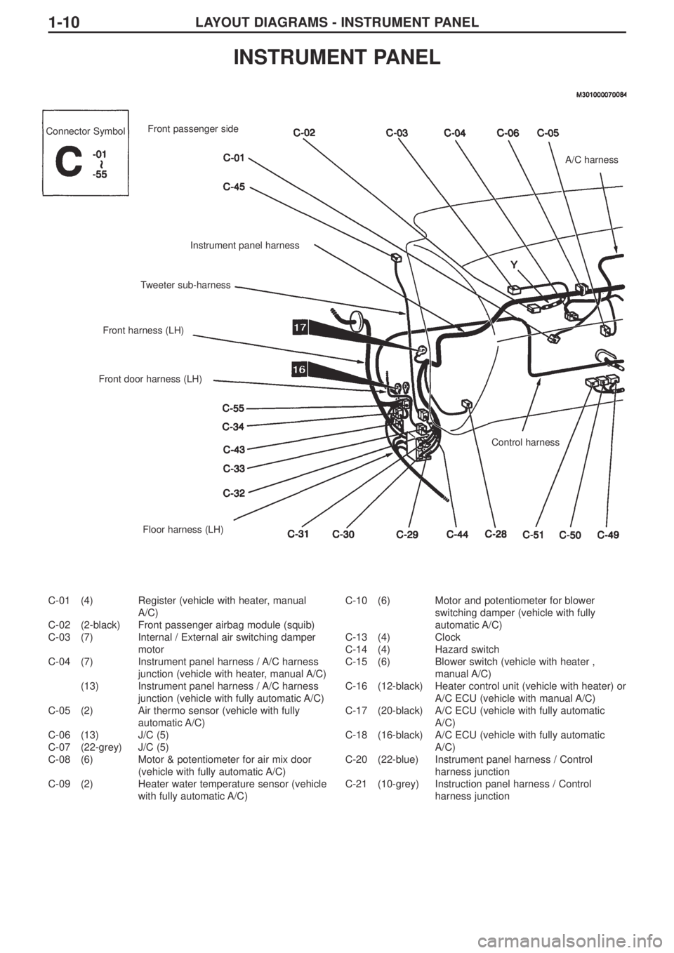
C-01 (4) Register (vehicle with heater, manual
A/C)
C-02 (2-black) Front passenger airbag module (squib)
C-03 (7) Internal / External air switching damper
motor
C-04 (7) Instrument panel harness / A/C harness
junction (vehicle with heater, manual A/C)
(13) Instrument panel harness / A/C harness
junction (vehicle with fully automatic A/C)
C-05 (2) Air thermo sensor (vehicle with fully
automatic A/C)
C-06 (13) J/C (5)
C-07 (22-grey) J/C (5)
C-08 (6) Motor & potentiometer for air mix door
(vehicle with fully automatic A/C)
C-09 (2) Heater water temperature sensor (vehicle
with fully automatic A/C)C-10 (6) Motor and potentiometer for blower
switching damper (vehicle with fully
automatic A/C)
C-13 (4) Clock
C-14 (4) Hazard switch
C-15 (6) Blower switch (vehicle with heater ,
manual A/C)
C-16 (12-black) Heater control unit (vehicle with heater) or
A/C ECU (vehicle with manual A/C)
C-17 (20-black) A/C ECU (vehicle with fully automatic
A/C)
C-18 (16-black) A/C ECU (vehicle with fully automatic
A/C)
C-20 (22-blue) Instrument panel harness / Control
harness junction
C-21 (10-grey) Instruction panel harness / Control
harness junction
INSTRUMENT PANEL
Connector Symbol
A/C harness
Control harness
Floor harness (LH) Front door harness (LH)Front harness (LH)Tweeter sub-harnessInstrument panel harness Front passenger side
Page 168 of 364
LAYOUT DIAGRAMS - DOORS1-18
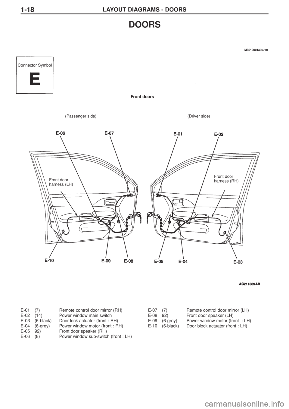
E-01 (7) Remote control door mirror (RH)
E-02 (14) Power window main switch
E-03 (6-black) Door lock actuator (front : RH)
E-04 (6-grey) Power window motor (front : RH)
E-05 92) Front door speaker (RH)
E-06 (8) Power window sub-switch (front : LH)E-07 (7) Remote control door mirror (LH)
E-08 92) Front door speaker (LH)
E-09 (6-grey) Power window motor (front : LH)
E-10 (6-black) Door block actuator (front : LH)
DOORS
Connector Symbol
(Passenger side) (Driver side)Front doors
Front door
harness (LH)Front door
harness (RH)
Page 169 of 364
LAYOUT DIAGRAMS - DOORS 1-19
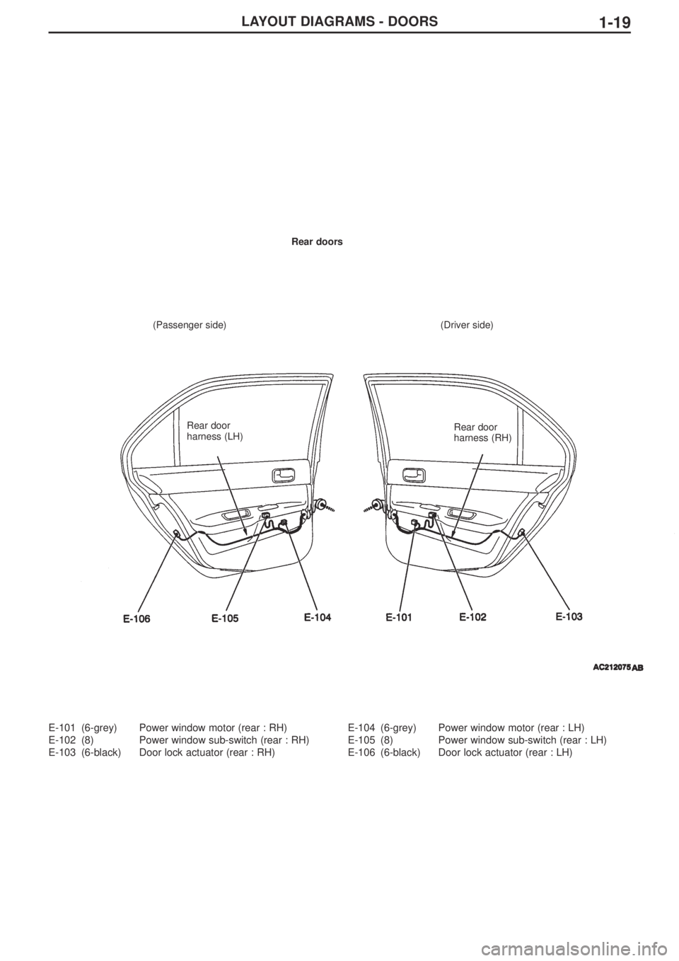
E-101 (6-grey) Power window motor (rear : RH)
E-102 (8) Power window sub-switch (rear : RH)
E-103 (6-black) Door lock actuator (rear : RH)E-104 (6-grey) Power window motor (rear : LH)
E-105 (8) Power window sub-switch (rear : LH)
E-106 (6-black) Door lock actuator (rear : LH)
Rear doors
(Passenger side) (Driver side)
Rear door
harness (LH)Rear door
harness (RH)
Page 188 of 364
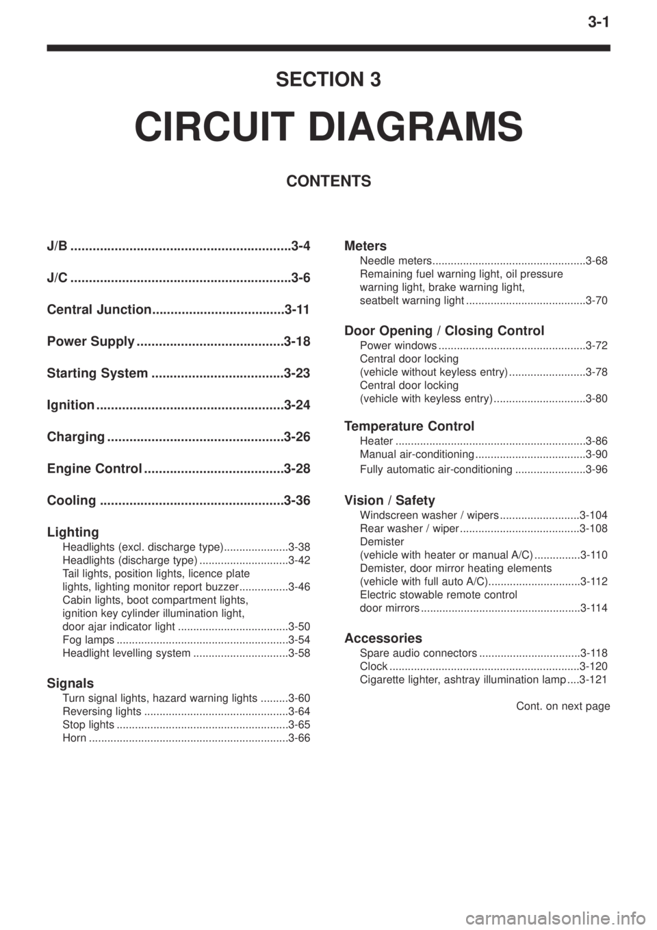
3-1
SECTION 3
CIRCUIT DIAGRAMS
CONTENTS
J/B ............................................................3-4
J/C ............................................................3-6
Central Junction....................................3-11
Power Supply ........................................3-18
Starting System ....................................3-23
Ignition ...................................................3-24
Charging ................................................3-26
Engine Control ......................................3-28
Cooling ..................................................3-36
Lighting
Headlights (excl. discharge type).....................3-38
Headlights (discharge type) .............................3-42
Tail lights, position lights, licence plate
lights, lighting monitor report buzzer................3-46
Cabin lights, boot compartment lights,
ignition key cylinder illumination light,
door ajar indicator light ....................................3-50
Fog lamps ........................................................3-54
Headlight levelling system ...............................3-58
Signals
Turn signal lights, hazard warning lights .........3-60
Reversing lights ...............................................3-64
Stop lights ........................................................3-65
Horn .................................................................3-66
Meters
Needle meters..................................................3-68
Remaining fuel warning light, oil pressure
warning light, brake warning light,
seatbelt warning light .......................................3-70
Door Opening / Closing Control
Power windows ................................................3-72
Central door locking
(vehicle without keyless entry) .........................3-78
Central door locking
(vehicle with keyless entry) ..............................3-80
Temperature Control
Heater ..............................................................3-86
Manual air-conditioning ....................................3-90
Fully automatic air-conditioning .......................3-96
Vision / Safety
Windscreen washer / wipers ..........................3-104
Rear washer / wiper .......................................3-108
Demister
(vehicle with heater or manual A/C) ...............3-110
Demister, door mirror heating elements
(vehicle with full auto A/C)..............................3-112
Electric stowable remote control
door mirrors ....................................................3-114
Accessories
Spare audio connectors .................................3-118
Clock ..............................................................3-120
Cigarette lighter, ashtray illumination lamp ....3-121
Cont. on next page
Page 193 of 364
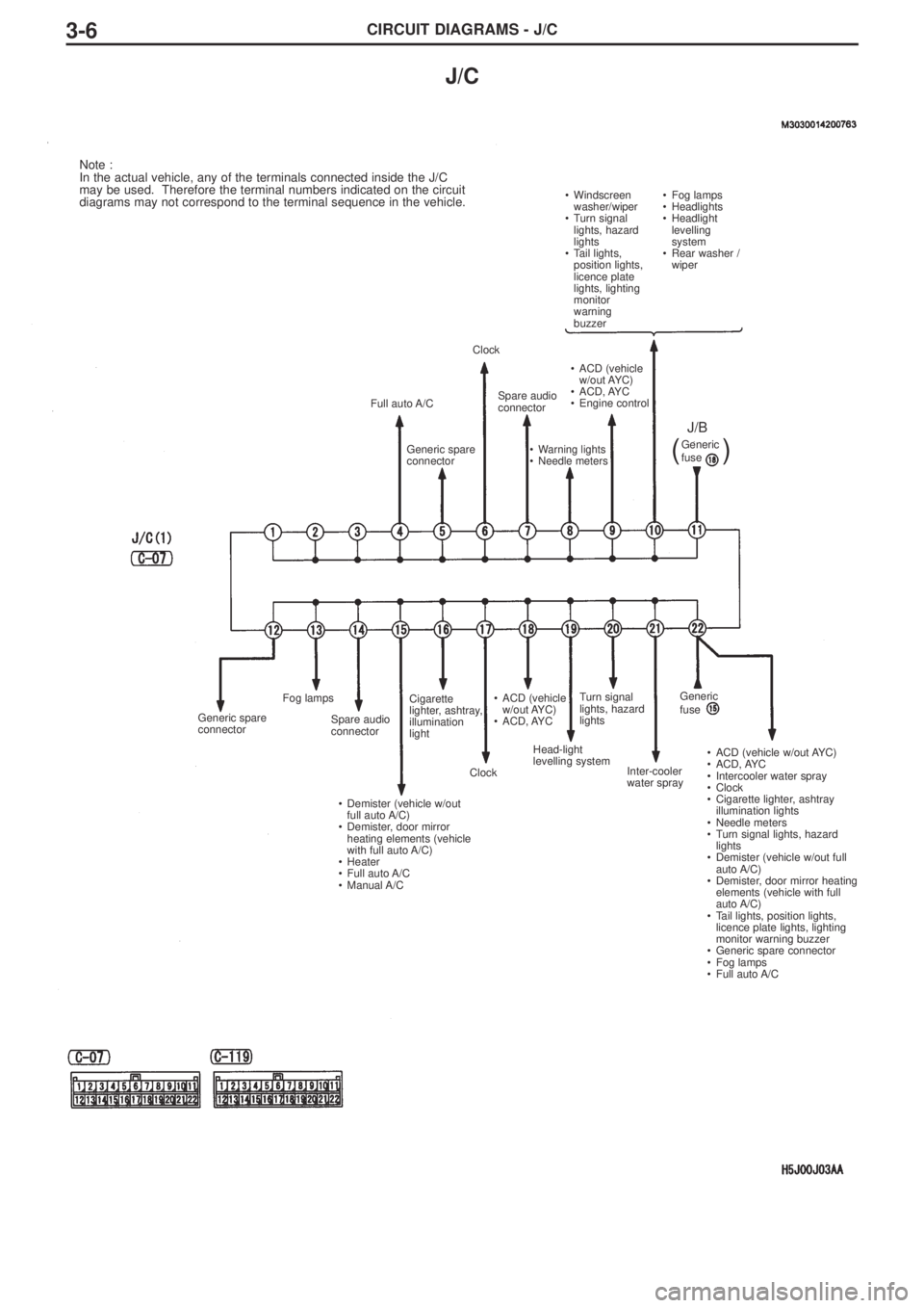
CIRCUIT DIAGRAMS - J/C3-6
J/C
Note :
In the actual vehicle, any of the terminals connected inside the J/C
may be used. Therefore the terminal numbers indicated on the circuit
diagrams may not correspond to the terminal sequence in the vehicle.
• Windscreen
washer/wiper
• Turn signal
lights, hazard
lights
• Tail lights,
position lights,
licence plate
lights, lighting
monitor
warning
buzzer•Fog lamps
•Headlights
•Headlight
levelling
system
•Rear washer /
wiper
Full auto A/C
Generic spare
connector
Generic spare
connectorFog lamps
Spare audio
connector
• Demister (vehicle w/out
full auto A/C)
• Demister, door mirror
heating elements (vehicle
with full auto A/C)
• Heater
• Full auto A/C
• Manual A/CCigarette
lighter, ashtray,
illumination
light
Clock• ACD (vehicle
w/out AYC)
• ACD, AYC
Head-light
levelling systemTurn signal
lights, hazard
lights
Inter-cooler
water spray• ACD (vehicle w/out AYC)
• ACD, AYC
• Intercooler water spray
• Clock
• Cigarette lighter, ashtray
illumination lights
• Needle meters
• Turn signal lights, hazard
lights
• Demister (vehicle w/out full
auto A/C)
• Demister, door mirror heating
elements (vehicle with full
auto A/C)
• Tail lights, position lights,
licence plate lights, lighting
monitor warning buzzer
• Generic spare connector
• Fog lamps
• Full auto A/C Clock
Spare audio
connector• ACD (vehicle
w/out AYC)
• ACD, AYC
• Engine control
• Warning lights
• Needle metersGeneric
fuse
J/B
(
)
Generic
fuse
Page 195 of 364
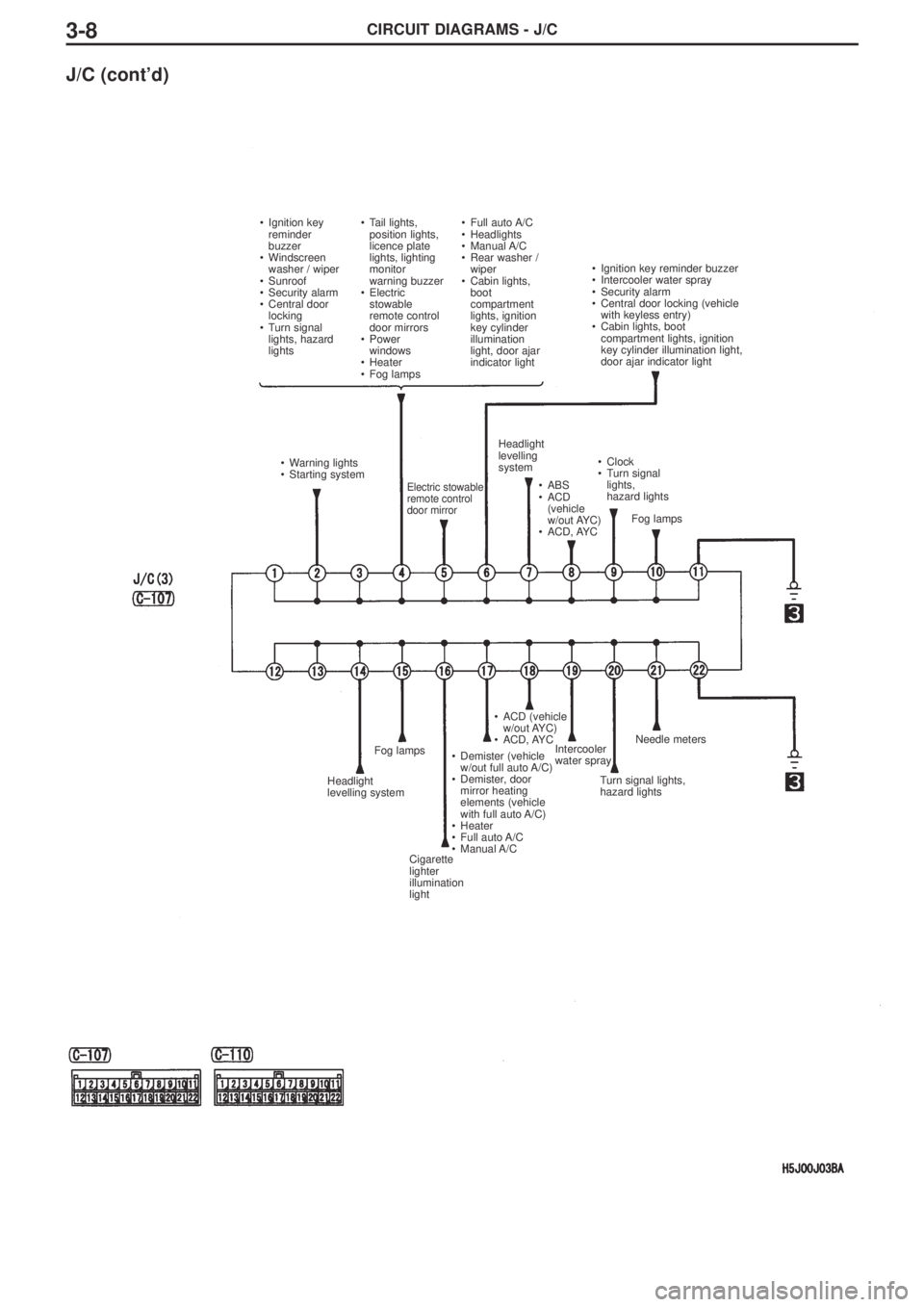
CIRCUIT DIAGRAMS - J/C3-8
J/C (cont’d)
•Ignition key
reminder
buzzer
•Windscreen
washer / wiper
•Sunroof
•Security alarm
•Central door
locking
•Turn signal
lights, hazard
lights•Tail lights,
position lights,
licence plate
lights, lighting
monitor
warning buzzer
•Electric
stowable
remote control
door mirrors
•Power
windows
•Heater
•Fog lamps•Full auto A/C
•Headlights
•Manual A/C
•Rear washer /
wiper
•Cabin lights,
boot
compartment
lights, ignition
key cylinder
illumination
light, door ajar
indicator light•Ignition key reminder buzzer
•Intercooler water spray
•Security alarm
•Central door locking (vehicle
with keyless entry)
•Cabin lights, boot
compartment lights, ignition
key cylinder illumination light,
door ajar indicator light
•Warning lights
•Starting system
Electric stowable
remote control
door mirror
Headlight
levelling
system
•ABS
•ACD
(vehicle
w/out AYC)
•ACD, AYC•Clock
•Turn signal
lights,
hazard lights
Fog lamps
Headlight
levelling systemFog lamps
Cigarette
lighter
illumination
light•Demister (vehicle
w/out full auto A/C)
•Demister, door
mirror heating
elements (vehicle
with full auto A/C)
•Heater
•Full auto A/C
•Manual A/C•ACD (vehicle
w/out AYC)
•ACD, AYC
Intercooler
water spray
Turn signal lights,
hazard lightsNeedle meters
Page 196 of 364
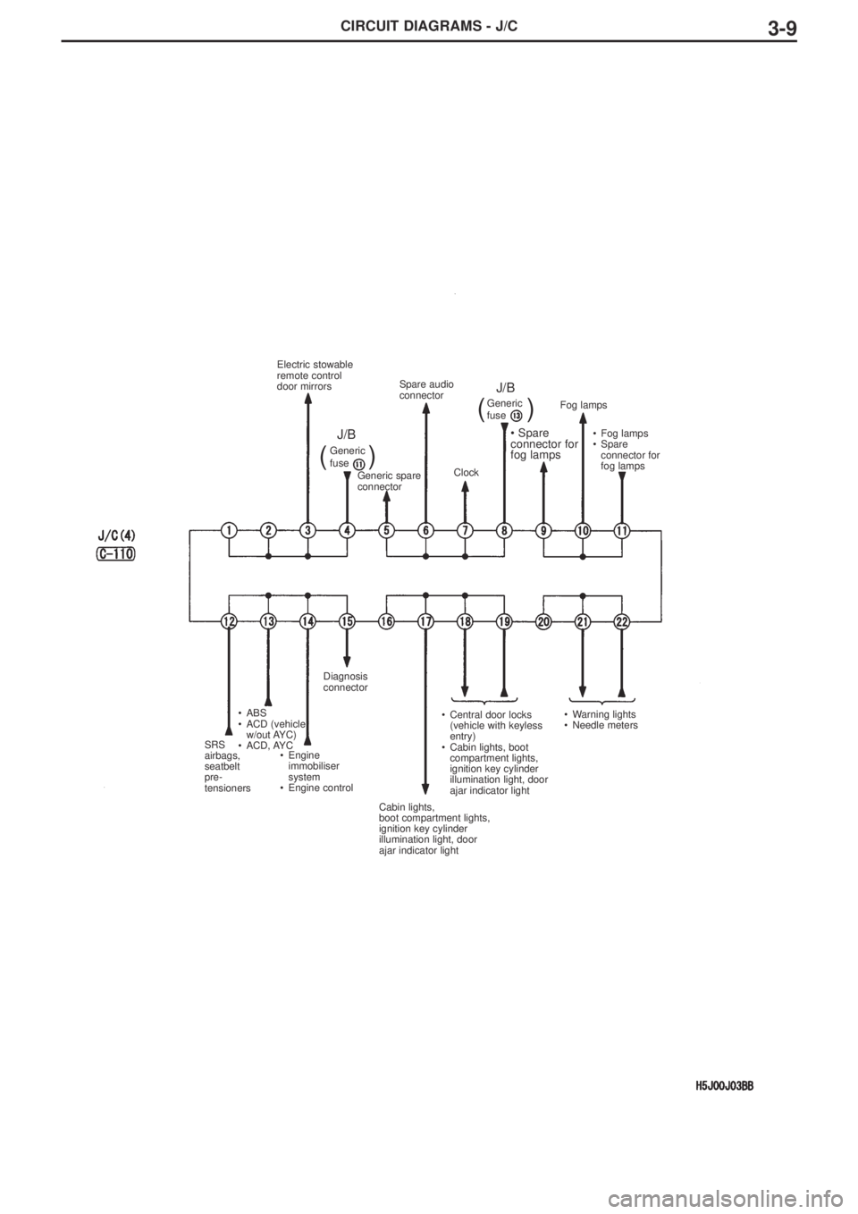
CIRCUIT DIAGRAMS - J/C3-9
SRS
airbags,
seatbelt
pre-
tensioners•ABS
•ACD (vehicle
w/out AYC)
•ACD, AYC
•Engine
immobiliser
system
•Engine controlDiagnosis
connector
Cabin lights,
boot compartment lights,
ignition key cylinder
illumination light, door
ajar indicator light•Central door locks
(vehicle with keyless
entry)
•Cabin lights, boot
compartment lights,
ignition key cylinder
illumination light, door
ajar indicator light•Warning lights
•Needle meters•Fog lamps
•Spare
connector for
fog lamps Fog lamps
• Spare
connector for
fog lamps
Clock Spare audio
connector
Generic spare
connector Electric stowable
remote control
door mirrors
Generic
fuseGeneric
fuse
J/BJ/B
((
))
Page 197 of 364
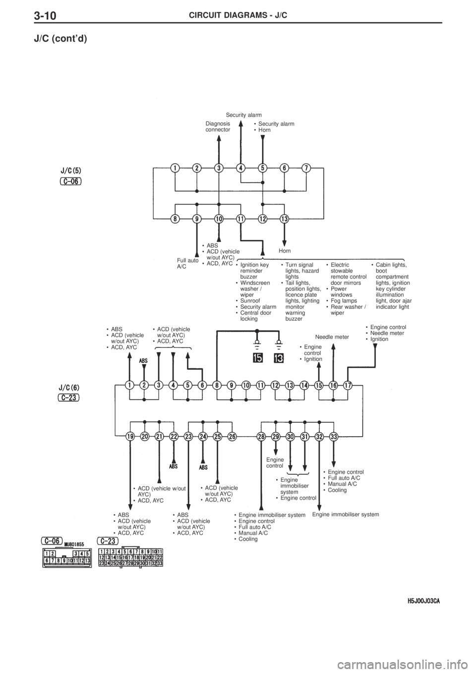
CIRCUIT DIAGRAMS - J/C3-10
J/C (cont’d)
Diagnosis
connector
Full auto
A/C
•ABS
•ACD (vehicle
w/out AYC)
•ACD, AYC•ACD (vehicle
w/out AYC)
•ACD, AYC
•Engine
control
•IgnitionNeedle meter•Engine control
•Needle meter
•Ignition
•Engine control
•Full auto A/C
•Manual A/C
•Cooling
Engine immobiliser system •Engine
immobiliser
system
•Engine control Engine
control
•Engine immobiliser system
•Engine control
•Full auto A/C
•Manual A/C
•Cooling •ACD (vehicle
w/out AYC)
•ACD, AYC
•ABS
•ACD (vehicle
w/out AYC)
•ACD, AYC •ACD (vehicle w/out
AYC)
•ACD, AYC
•ABS
•ACD (vehicle
w/out AYC)
•ACD, AYC •ABS
•ACD (vehicle
w/out AYC)
•ACD, AYC•Security alarm
•Horn Security alarm
Horn
•Ignition key
reminder
buzzer
•Windscreen
washer /
wiper
•Sunroof
•Security alarm
•Central door
locking•Turn signal
lights, hazard
lights
•Tail lights,
position lights,
licence plate
lights, lighting
monitor
warning
buzzer •Electric
stowable
remote control
door mirrors
•Power
windows
•Fog lamps
•Rear washer /
wiper •Cabin lights,
boot
compartment
lights, ignition
key cylinder
illumination
light, door ajar
indicator light
Page 205 of 364
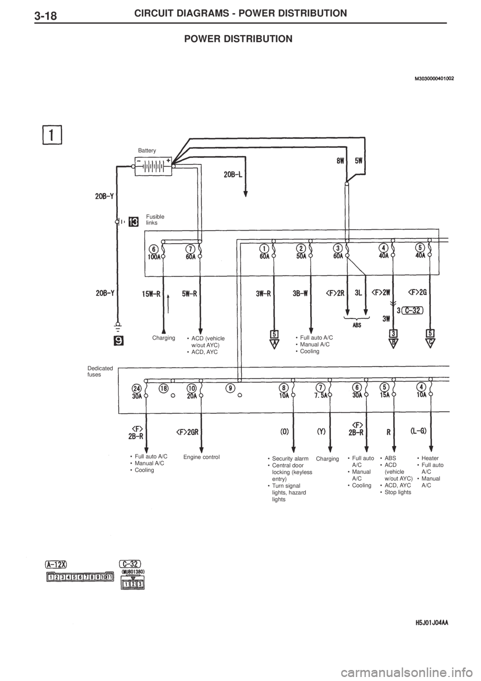
3-18CIRCUIT DIAGRAMS - POWER DISTRIBUTION
Battery
Fusible
links
Charging
Charging •ACD (vehicle
w/out AYC)
•ACD, AYC•Full auto A/C
•Manual A/C
•Cooling
Dedicated
fuses
•Full auto A/C
•Manual A/C
•CoolingEngine control
•Security alarm
•Central door
locking (keyless
entry)
•Turn signal
lights, hazard
lights•Full auto
A/C
•Manual
A/C
•Cooling•ABS
•ACD
(vehicle
w/out AYC)
•ACD, AYC
•Stop lights•Heater
•Full auto
A/C
•Manual
A/C
POWER DISTRIBUTION