ENGINE – TIMING BELT, TIMING BELT B11-24
2.
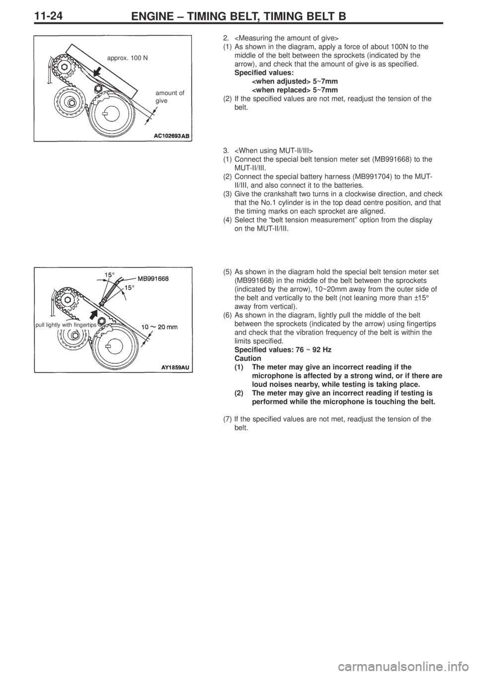
(1) As shown in the diagram, apply a force of about 100N to the
middle of the belt between the sprockets (indicated by the
arrow), and check that the amount of give is as specified.
Specified values:
5~7mm
5~7mm
(2) If the specified values are not met, readjust the tension of the
belt.
3.
(1) Connect the special belt tension meter set (MB991668) to the
MUT-II/III.
(2) Connect the special battery harness (MB991704) to the MUT-
II/III, and also connect it to the batteries.
(3) Give the crankshaft two turns in a clockwise direction, and check
that the No.1 cylinder is in the top dead centre position, and that
the timing marks on each sprocket are aligned.
(4) Select the “belt tension measurement” option from the display
on the MUT-II/III.
(5) As shown in the diagram hold the special belt tension meter set
(MB991668) in the middle of the belt between the sprockets
(indicated by the arrow), 10~20mm away from the outer side of
the belt and vertically to the belt (not leaning more than ±15°
away from vertical).
(6) As shown in the diagram, lightly pull the middle of the belt
between the sprockets (indicated by the arrow) using fingertips
and check that the vibration frequency of the belt is within the
limits specified.
Specified values: 76 ~ 92 Hz
Caution
(1) The meter may give an incorrect reading if the
microphone is affected by a strong wind, or if there are
loud noises nearby, while testing is taking place.
(2) The meter may give an incorrect reading if testing is
performed while the microphone is touching the belt.
(7) If the specified values are not met, readjust the tension of the
belt.
approx. 100 N
amount of
give
pull lightly with fingertips
