reset MITSUBISHI LANCER EVOLUTION IX 2005 Workshop Manual
[x] Cancel search | Manufacturer: MITSUBISHI, Model Year: 2005, Model line: LANCER EVOLUTION IX, Model: MITSUBISHI LANCER EVOLUTION IX 2005Pages: 364, PDF Size: 14.38 MB
Page 45 of 364

MPI – TROUBLESHOOTING
13A-5
TROUBLESHOOTING
1. Diagnosis Functions
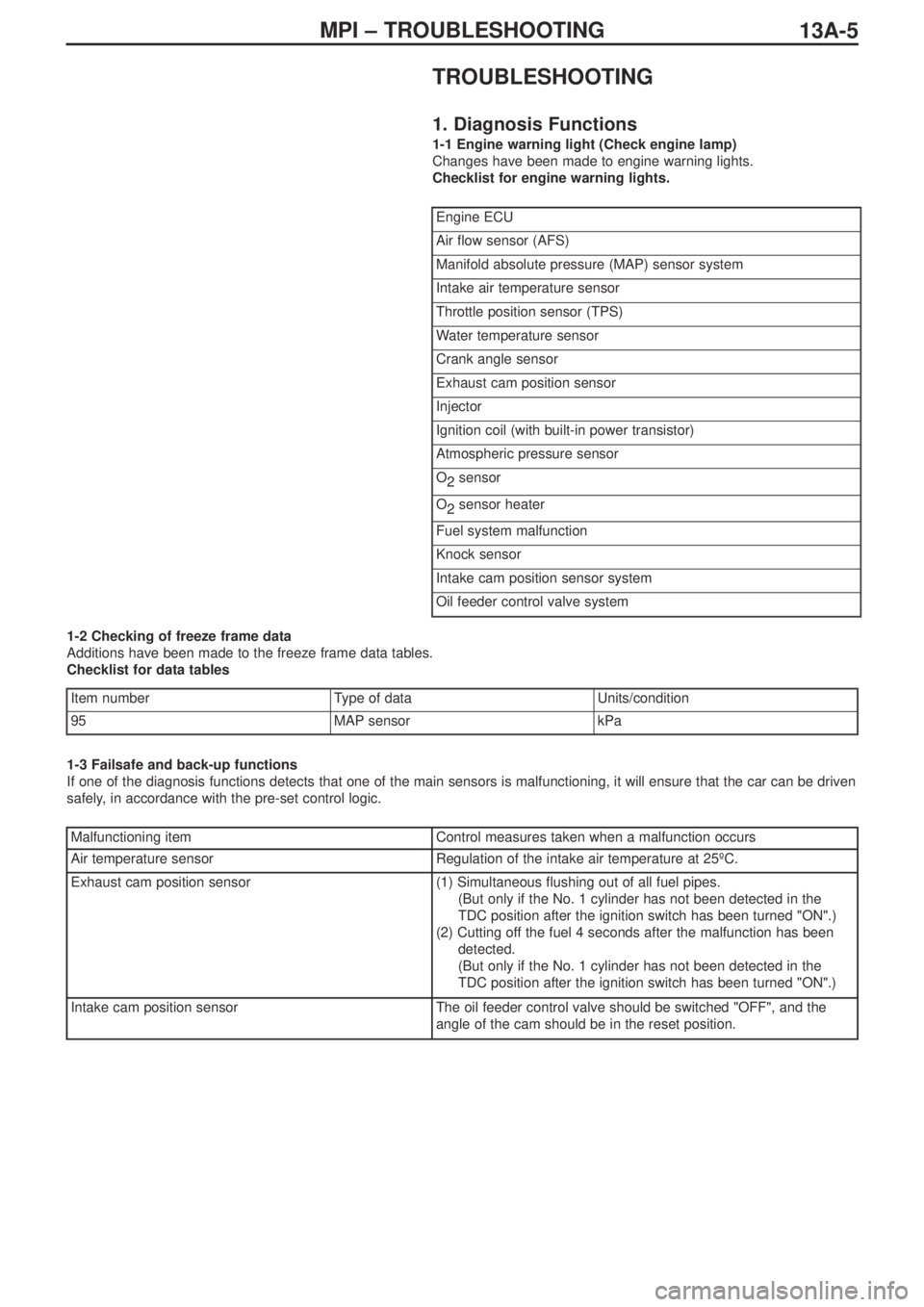
1-1 Engine warning light (Check engine lamp)
Changes have been made to engine warning lights.
Checklist for engine warning lights.
1-2 Checking of freeze frame data
Additions have been made to the freeze frame data tables.
Checklist for data tables
1-3 Failsafe and back-up functions
If one of the diagnosis functions detects that one of the main sensors is malfunctioning, it will ensure that the car can be driven
safely, in accordance with the pre-set control logic.
Engine ECU
Air flow sensor (AFS)
Manifold absolute pressure (MAP) sensor system
Intake air temperature sensor
Throttle position sensor (TPS)
Water temperature sensor
Crank angle sensor
Exhaust cam position sensor
Injector
Ignition coil (with built-in power transistor)
Atmospheric pressure sensor
O
2sensor
O
2sensor heater
Fuel system malfunction
Knock sensor
Intake cam position sensor system
Oil feeder control valve system
Item numberType of data Units/condition
95MAP sensorkPa
Malfunctioning itemControl measures taken when a malfunction occurs
Air temperature sensorRegulation of the intake air temperature at 25ºC.
Exhaust cam position sensor(1) Simultaneous flushing out of all fuel pipes.
(But only if the No. 1 cylinder has not been detected in the
TDC position after the ignition switch has been turned "ON".)
(2) Cutting off the fuel 4 seconds after the malfunction has been
detected.
(But only if the No. 1 cylinder has not been detected in the
TDC position after the ignition switch has been turned "ON".)
Intake cam position sensorThe oil feeder control valve should be switched "OFF", and the
angle of the cam should be in the reset position.
Page 68 of 364

13A-28MPI – TROUBLESHOOTING
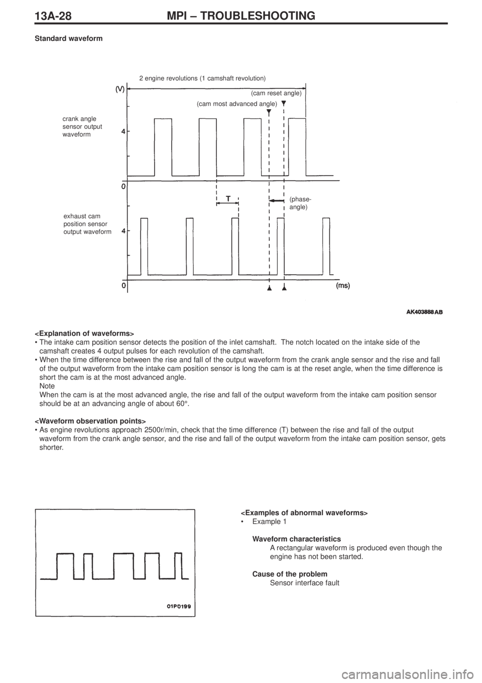
Standard waveform
2 engine revolutions (1 camshaft revolution)
crank angle
sensor output
waveform
exhaust cam
position sensor
output waveform(cam reset angle)
(cam most advanced angle)
(phase-
angle)
•The intake cam position sensor detects the position of the inlet camshaft. The notch located on the intake side of the
camshaft creates 4 output pulses for each revolution of the camshaft.
•When the time difference between the rise and fall of the output waveform from the crank angle sensor and the rise and fall
of the output waveform from the intake cam position sensor is long the cam is at the reset angle, when the time difference is
short the cam is at the most advanced angle.
Note
When the cam is at the most advanced angle, the rise and fall of the output waveform from the intake cam position sensor
should be at an advancing angle of about 60°.
•As engine revolutions approach 2500r/min, check that the time difference (T) between the rise and fall of the output
waveform from the crank angle sensor, and the rise and fall of the output waveform from the intake cam position sensor, gets
shorter.
•Example 1
Waveform characteristics
Arectangular waveform is produced even though the
engine has not been started.
Cause of the problem
Sensor interface fault