MITSUBISHI LANCER EVOLUTION VIII 2004 Owner's Manual
LANCER EVOLUTION VIII 2004
MITSUBISHI
MITSUBISHI
https://www.carmanualsonline.info/img/19/57325/w960_57325-0.png
MITSUBISHI LANCER EVOLUTION VIII 2004 Owner's Manual
Page 105 of 166
WIRING DIAGRAMS - BOOT INTERIOR1-6
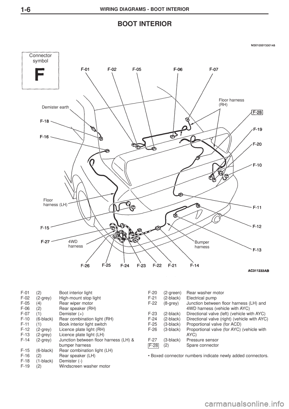
BOOT INTERIOR
F-01 (2) Boot interior light
F-02 (2-grey) High-mount stop light
F-05 (4) Rear wiper motor
F-06 (2) Rear speaker (RH)
F-07 (1) Demister (+)
F-10 (6-black) Rear combination light (RH)
F-11 (1) Book interior light switch
F-12 (2-grey) Licence plate light (RH)
F-13 (2-grey) Licence plate light (LH)
F-14 (2-grey) Junction between floor harness (LH) &
bumper harness
F-15 (6-black) Rear combination light (LH)
F-16 (2) Rear speaker (LH)
F-18 (1-black) Demister (-)
F-19 (2) Windscreen washer motorF-20 (2-green) Rear washer motor
F-21 (2-black) Electrical pump
F-22 (8-grey) Junction between floor harness (LH) and
4WD harness (vehicle with AYC)
F-23 (2-black) Directional valve (left) (vehicle with AYC)
F-24 (2-black) Directional valve (right) (vehicle with AYC)
F-25 (3-black) Proportional valve (for ACD)
F-26 (3-black) Proportional valve (for AYC) (vehicle with
AYC)
F-27 (3-black) Pressure sensor
(2) Spare connector
• Boxed connector numbers indicate newly added connectors.
F-28
Demister earth
Floor
harness (LH)
4WD
harnessBumper
harness
Floor harness
(RH)
Connector
symbol
Page 110 of 166
COMPONENT INSTALLATION POSITIONS - J/C3-3
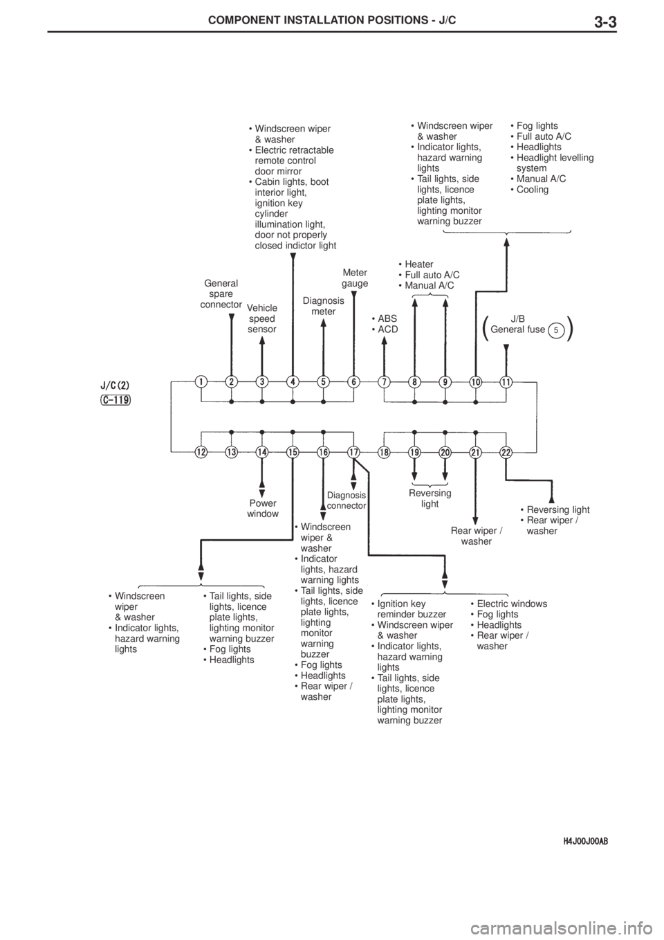
•Windscreen wiper
& washer
•Indicator lights,
hazard warning
lights
•Tail lights, side
lights, licence
plate lights,
lighting monitor
warning buzzer•Fog lights
•Full auto A/C
•Headlights
•Headlight levelling
system
•Manual A/C
•Cooling•Windscreen wiper
& washer
•Electric retractable
remote control
door mirror
•Cabin lights, boot
interior light,
ignition key
cylinder
illumination light,
door not properly
closed indictor light
•Heater
•Full auto A/C
•Manual A/C
•ABS
•ACD
Meter
gauge
Diagnosis
meterVehicle
speed
sensor
General
spare
connector
Power
window
•Windscreen
wiper
& washer
•Indicator lights,
hazard warning
lights•Tail lights, side
lights, licence
plate lights,
lighting monitor
warning buzzer
•Fog lights
•Headlights•Ignition key
reminder buzzer
•Windscreen wiper
& washer
•Indicator lights,
hazard warning
lights
•Tail lights, side
lights, licence
plate lights,
lighting monitor
warning buzzer•Electric windows
•Fog lights
•Headlights
•Rear wiper /
washer
•Windscreen
wiper &
washer
•Indicator
lights, hazard
warning lights
•Tail lights, side
lights, licence
plate lights,
lighting
monitor
warning
buzzer
•Fog lights
•Headlights
•Rear wiper /
washer
•Reversing light
•Rear wiper /
washer
Rear wiper /
washer
Reversing
lightDiagnosis
connector
J/B
General fuse
()5
Page 116 of 166
CIRCUIT DIAGRAMS - CENTRAL JUNCTION3-9
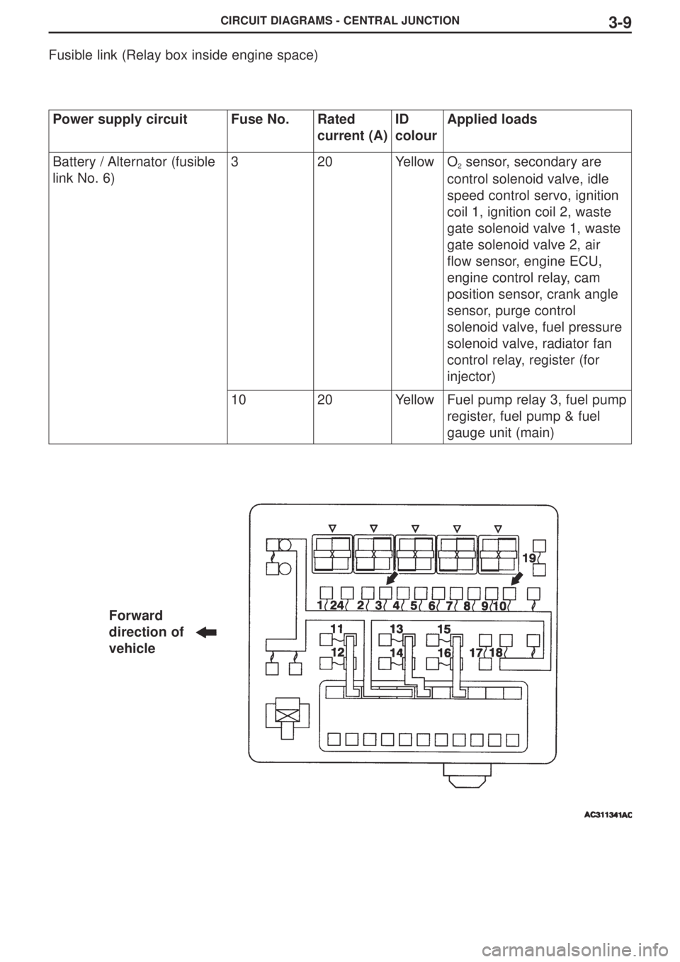
Fusible link (Relay box inside engine space)
Power supply circuitFuse No.Rated
current (A)ID
colourApplied loads
Battery / Alternator (fusible
link No. 6)320YellowO2sensor, secondary are
control solenoid valve, idle
speed control servo, ignition
coil 1, ignition coil 2, waste
gate solenoid valve 1, waste
gate solenoid valve 2, air
flow sensor, engine ECU,
engine control relay, cam
position sensor, crank angle
sensor, purge control
solenoid valve, fuel pressure
solenoid valve, radiator fan
control relay, register (for
injector)
1020YellowFuel pump relay 3, fuel pump
register, fuel pump & fuel
gauge unit (main)
Forward
direction of
vehicle
Page 125 of 166
CIRCUIT DIAGRAMS - ENGINE CONTROL3-18
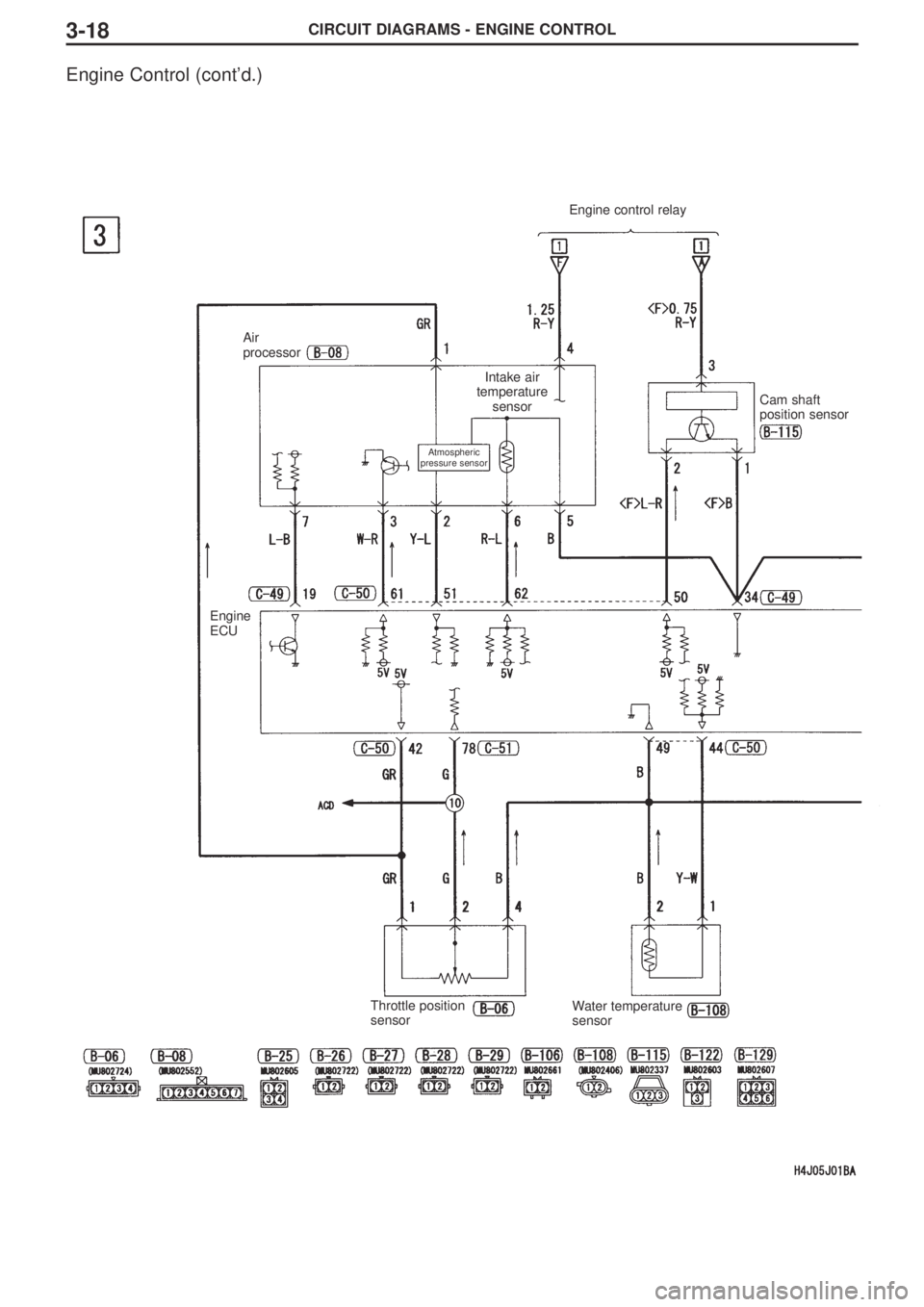
Engine Control (cont’d.)
Engine control relay
Air
processor
Engine
ECU
Throttle position
sensorWater temperature
sensor
Atmospheric
pressure sensor
Intake air
temperature
sensor
Cam shaft
position sensor
Page 126 of 166
CIRCUIT DIAGRAMS - ENGINE CONTROL3-19
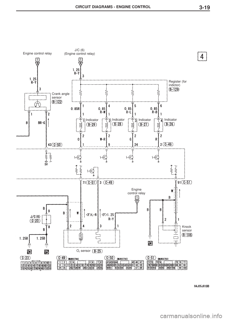
Engine control relayJ/C (6)
(Engine control relay)
Crank angle
sensor
Register (for
indictor)
IndicatorIndicatorIndicatorIndicator
Engine
control relay
Knock
sensor
O2sensor
Page 129 of 166
CIRCUIT DIAGRAMS - ENGINE CONTROL3-22
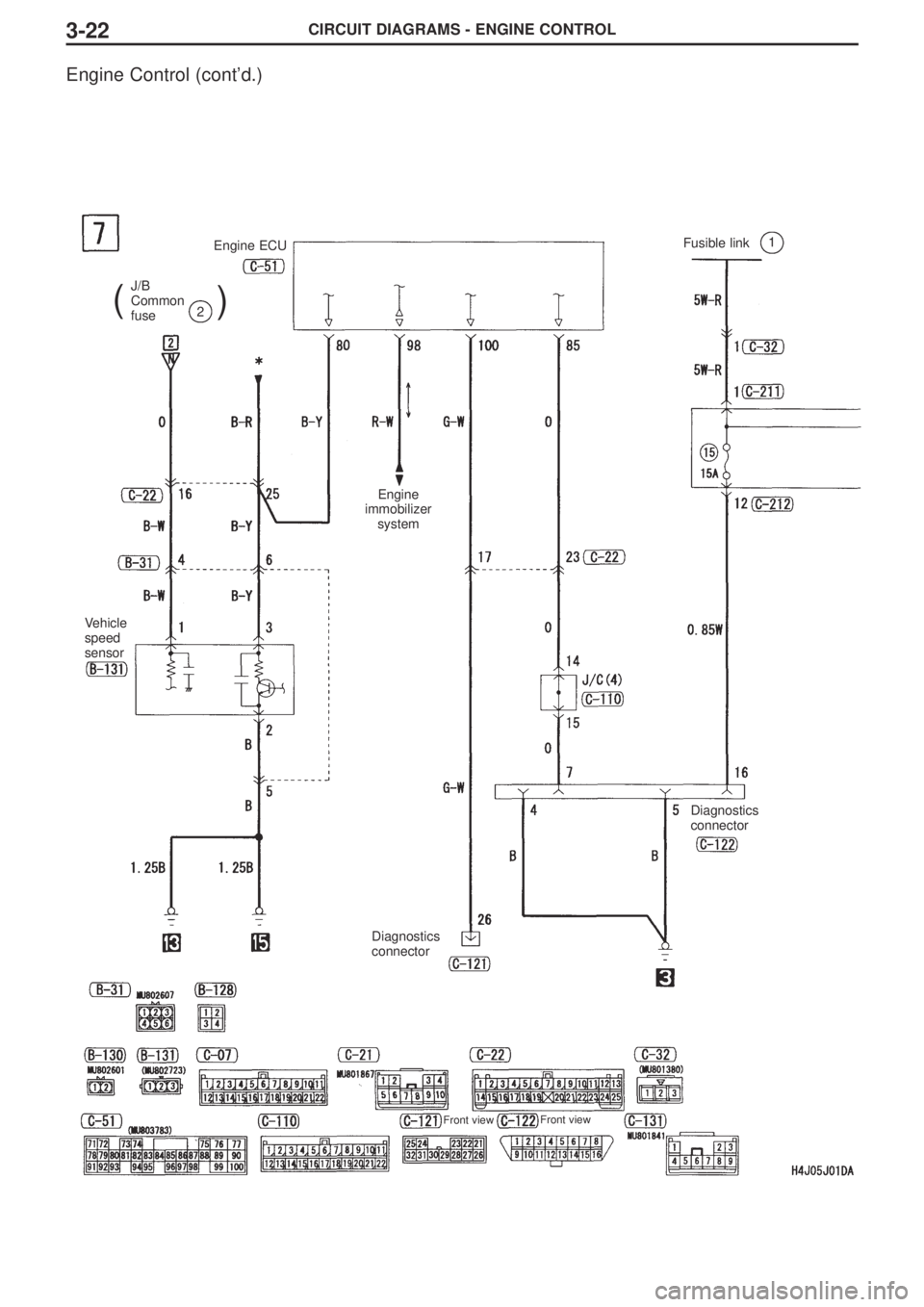
Engine Control (cont’d.)
J/B
Common
fuse
()2
Fusible link1Engine ECU
Vehicle
speed
sensor
Engine
immobilizer
system
Diagnostics
connector
Diagnostics
connector
Front viewFront view
Page 134 of 166
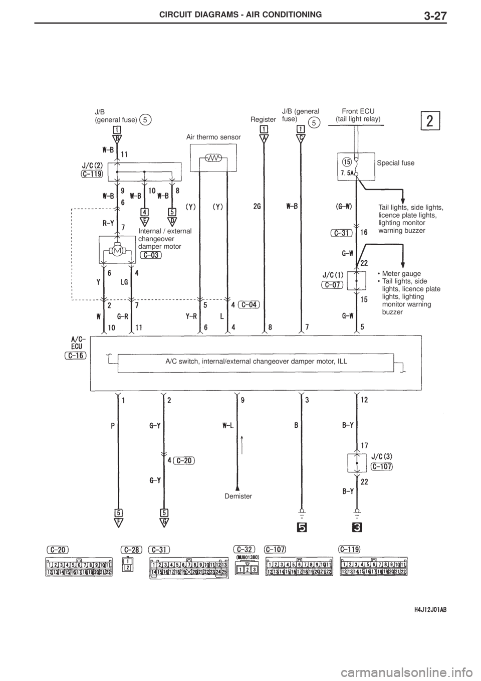
CIRCUIT DIAGRAMS - AIR CONDITIONING3-27
J/B
(general fuse)5
J/B (general
fuse)
5
Front ECU
(tail light relay)
Register
Air thermo sensor
Internal / external
changeover
damper motor
Special fuse
Tail lights, side lights,
licence plate lights,
lighting monitor
warning buzzer
•Meter gauge
•Tail lights, side
lights, licence plate
lights, lighting
monitor warning
buzzer
A/C switch, internal/external changeover damper motor, ILL
Demister
Page 141 of 166
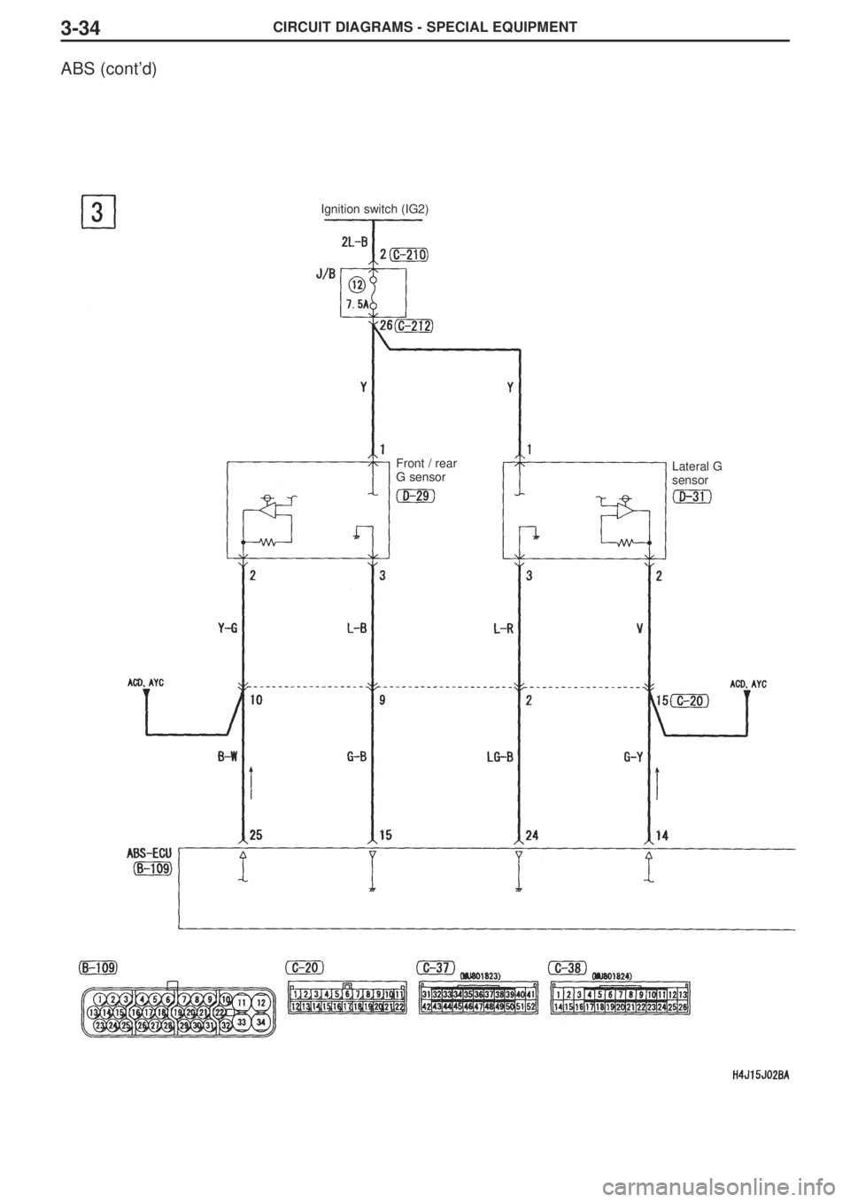
CIRCUIT DIAGRAMS - SPECIAL EQUIPMENT3-34
ABS (cont’d)
Ignition switch (IG2)
Front / rear
G sensorLateral G
sensor
Page 143 of 166
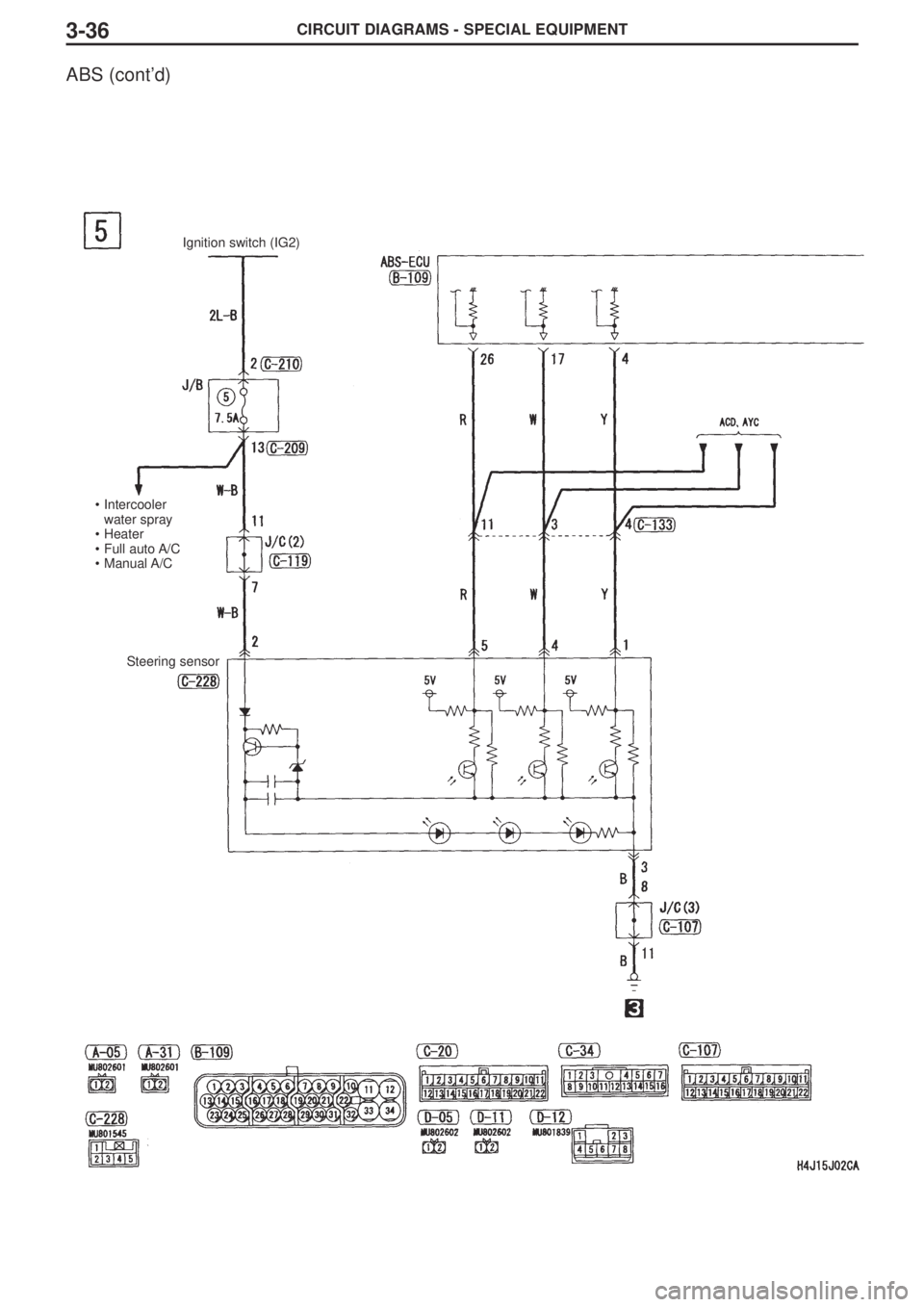
CIRCUIT DIAGRAMS - SPECIAL EQUIPMENT3-36
ABS (cont’d)
Ignition switch (IG2)
•Intercooler
water spray
•Heater
•Full auto A/C
•Manual A/C
Steering sensor
Page 144 of 166
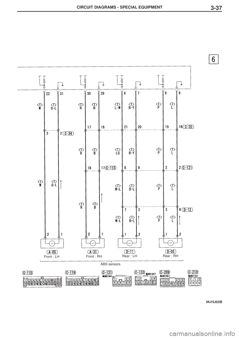
CIRCUIT DIAGRAMS - SPECIAL EQUIPMENT3-37
Front : LHFront : RHRear : LHRear : RH
ABS sensors


